EP3242016A1 - Dispositif de remplissage d'un réservoir de véhicule automobile en carburant gazeux ou liquide, en particulier pour le premier remplissage industriel sur une chaîne de fabrication du fabricant - Google Patents
Dispositif de remplissage d'un réservoir de véhicule automobile en carburant gazeux ou liquide, en particulier pour le premier remplissage industriel sur une chaîne de fabrication du fabricant Download PDFInfo
- Publication number
- EP3242016A1 EP3242016A1 EP17168732.0A EP17168732A EP3242016A1 EP 3242016 A1 EP3242016 A1 EP 3242016A1 EP 17168732 A EP17168732 A EP 17168732A EP 3242016 A1 EP3242016 A1 EP 3242016A1
- Authority
- EP
- European Patent Office
- Prior art keywords
- tank
- hollow cylinder
- piston
- pump
- filling
- Prior art date
- Legal status (The legal status is an assumption and is not a legal conclusion. Google has not performed a legal analysis and makes no representation as to the accuracy of the status listed.)
- Withdrawn
Links
- 239000012530 fluid Substances 0.000 title description 9
- 239000007788 liquid Substances 0.000 claims abstract description 13
- 238000003860 storage Methods 0.000 claims abstract description 9
- XLYOFNOQVPJJNP-UHFFFAOYSA-N water Substances O XLYOFNOQVPJJNP-UHFFFAOYSA-N 0.000 claims description 11
- 238000005187 foaming Methods 0.000 abstract description 3
- 239000004202 carbamide Substances 0.000 description 7
- XSQUKJJJFZCRTK-UHFFFAOYSA-N Urea Chemical compound NC(N)=O XSQUKJJJFZCRTK-UHFFFAOYSA-N 0.000 description 6
- 238000011161 development Methods 0.000 description 2
- 230000018109 developmental process Effects 0.000 description 2
- 238000006073 displacement reaction Methods 0.000 description 2
- 239000006260 foam Substances 0.000 description 2
- 239000000446 fuel Substances 0.000 description 2
- 238000004519 manufacturing process Methods 0.000 description 2
- -1 AD Blue Substances 0.000 description 1
- 244000025254 Cannabis sativa Species 0.000 description 1
- 235000012766 Cannabis sativa ssp. sativa var. sativa Nutrition 0.000 description 1
- 235000012765 Cannabis sativa ssp. sativa var. spontanea Nutrition 0.000 description 1
- 238000004378 air conditioning Methods 0.000 description 1
- TZCXTZWJZNENPQ-UHFFFAOYSA-L barium sulfate Chemical compound [Ba+2].[O-]S([O-])(=O)=O TZCXTZWJZNENPQ-UHFFFAOYSA-L 0.000 description 1
- 230000015572 biosynthetic process Effects 0.000 description 1
- 235000009120 camo Nutrition 0.000 description 1
- 235000005607 chanvre indien Nutrition 0.000 description 1
- 238000010276 construction Methods 0.000 description 1
- 239000002826 coolant Substances 0.000 description 1
- 239000000498 cooling water Substances 0.000 description 1
- 238000002425 crystallisation Methods 0.000 description 1
- 230000008025 crystallization Effects 0.000 description 1
- 230000001419 dependent effect Effects 0.000 description 1
- 230000000694 effects Effects 0.000 description 1
- 239000003344 environmental pollutant Substances 0.000 description 1
- 238000005429 filling process Methods 0.000 description 1
- 239000011487 hemp Substances 0.000 description 1
- 239000012528 membrane Substances 0.000 description 1
- 238000000034 method Methods 0.000 description 1
- 239000000203 mixture Substances 0.000 description 1
- 239000010705 motor oil Substances 0.000 description 1
- 231100000719 pollutant Toxicity 0.000 description 1
- 238000003825 pressing Methods 0.000 description 1
- 238000005086 pumping Methods 0.000 description 1
- 238000007789 sealing Methods 0.000 description 1
- 150000003672 ureas Chemical class 0.000 description 1
Images


Classifications
-
- F—MECHANICAL ENGINEERING; LIGHTING; HEATING; WEAPONS; BLASTING
- F04—POSITIVE - DISPLACEMENT MACHINES FOR LIQUIDS; PUMPS FOR LIQUIDS OR ELASTIC FLUIDS
- F04B—POSITIVE-DISPLACEMENT MACHINES FOR LIQUIDS; PUMPS
- F04B5/00—Machines or pumps with differential-surface pistons
- F04B5/02—Machines or pumps with differential-surface pistons with double-acting pistons
-
- F—MECHANICAL ENGINEERING; LIGHTING; HEATING; WEAPONS; BLASTING
- F04—POSITIVE - DISPLACEMENT MACHINES FOR LIQUIDS; PUMPS FOR LIQUIDS OR ELASTIC FLUIDS
- F04B—POSITIVE-DISPLACEMENT MACHINES FOR LIQUIDS; PUMPS
- F04B13/00—Pumps specially modified to deliver fixed or variable measured quantities
-
- F—MECHANICAL ENGINEERING; LIGHTING; HEATING; WEAPONS; BLASTING
- F04—POSITIVE - DISPLACEMENT MACHINES FOR LIQUIDS; PUMPS FOR LIQUIDS OR ELASTIC FLUIDS
- F04B—POSITIVE-DISPLACEMENT MACHINES FOR LIQUIDS; PUMPS
- F04B13/00—Pumps specially modified to deliver fixed or variable measured quantities
- F04B13/02—Pumps specially modified to deliver fixed or variable measured quantities of two or more fluids at the same time
-
- F—MECHANICAL ENGINEERING; LIGHTING; HEATING; WEAPONS; BLASTING
- F04—POSITIVE - DISPLACEMENT MACHINES FOR LIQUIDS; PUMPS FOR LIQUIDS OR ELASTIC FLUIDS
- F04B—POSITIVE-DISPLACEMENT MACHINES FOR LIQUIDS; PUMPS
- F04B23/00—Pumping installations or systems
- F04B23/02—Pumping installations or systems having reservoirs
-
- F—MECHANICAL ENGINEERING; LIGHTING; HEATING; WEAPONS; BLASTING
- F04—POSITIVE - DISPLACEMENT MACHINES FOR LIQUIDS; PUMPS FOR LIQUIDS OR ELASTIC FLUIDS
- F04B—POSITIVE-DISPLACEMENT MACHINES FOR LIQUIDS; PUMPS
- F04B2201/00—Pump parameters
- F04B2201/02—Piston parameters
- F04B2201/0201—Position of the piston
Definitions
- the present invention relates to a device for filling a tank of a motor vehicle with a liquid or gaseous operating means, in particular for initial industrial filling on the assembly line of the manufacturer according to the preamble of claim 1.
- Each motor vehicle is before delivery by the manufacturer with different liquids, such. As fuel, mopping water, coolant or the like filled. This is usually done during final assembly on the manufacturer's assembly line.
- Such a device is for example from the DE 10 2014 011 051 A1 known.
- the cycle time is determined by various specifications and amounts to about 60 seconds per vehicle for some manufacturers.
- the tank to be filled of the motor vehicle during the movement of the motor vehicle with the desired resources such as fuel, mop water, AD Blue, cooling water, engine oil, brake fluid or air conditioning gas must be filled. Because this filling operation takes place when the vehicle is running, the device for filling must be accelerated to the speed of the vehicle and returned to the starting position at the end of the filling process, in order then to be ready for filling the next motor vehicle after approximately 60 seconds.
- the present invention is based on the finding that, in the case of a centrifugal pump or in the case of a membrane pump, the medium is transported by a brief increase in pressure and subsequent reduction in pressure, the fluid being swirled around the pump.
- This turbulence generated by the pump leads to foam formation, at least in some operating means, whereby a large volume is created and as a result of which the tank is filled prematurely, so that part of the operating medium again emerges from the tank and is lost. In the prior art, this is countered with a reduced volume flow.
- the present invention has the object to provide a device for filling a tank of a motor vehicle with a liquid or gaseous operating means of the type mentioned, which avoids foaming despite a large volume flow or at least reduced.
- a device designed according to this technical teaching has the advantage that the piston is moved linearly and very evenly, thereby pressing the operating medium relatively evenly out of the hollow cylinder through the tank hose and the filling adapter into the tank of the motor vehicle.
- the known from the prior art pumping movement is avoided, which is why the pump according to the invention generates significantly less turbulence of the equipment and therefore the Betreibsstoff reaches the tank of the vehicle with a comparatively high volume flow, whereby the filling time is drastically reduced.
- both the tank hose, as well as the supply line is connected to an end face of the hollow cylinder to the pump.
- the volume of the equipment transported out of the hollow cylinder is determined from the product of the cross section with the axial path traveled by the piston.
- the latter can be controlled via the drive in a conventional manner.
- means for determining the exact position of the piston within the hollow cylinder This has, inter alia, the advantage that this can be dispensed with a complex flow meter in the tank hose, which on the one hand reduces the cost and on the other hand, the movable mass of the device.
- Another advantage is that, in this way, the volume of the dispensed fluid can be determined much more accurately, since the inaccuracy known in the flowmeter system is eliminated.
- Yet another advantage is that the turbulences occurring at the flow meter are eliminated, which also contributes to a reduction of foaming.
- a first resource chamber for temporarily receiving a resource is provided at the front of the piston, while a second resource chamber for temporarily receiving the same resource is formed on the back of the piston.
- Both equipment chambers are housed within the hollow cylinder and are separated by the piston. This has the advantage that the device can accommodate almost twice as much resources with the same size.
- a closed wall is provided on the second end face of the hollow cylinder for limiting the second operating medium chamber, in which a second inlet and / or a second outlet valve is housed, to which a suitable tank hose and / or a suitable supply line can be attached, depending on the application.
- the common piston depending on its position within the hollow cylinder affects the size of the first and the second resource chamber, it is possible that at the same time new equipment is inserted into the second resource chamber when pushing out the resource from the first resource chamber. As soon as the first resource chamber is completely emptied and the piston is pressed in the opposite direction, the second resource chamber is emptied and at the same time the first resource chamber is refilled. It is understood that the involved intake and exhaust valves are controlled accordingly.
- a single supply line and a single tank hose together with a single filling adapter is connected to this double-sided usable pump, wherein both the supply line, and the tank hose are Y-shaped and both at a first, and at a second End face of the hollow cylinder are connected to reach the first and the second Betreibsschhunt.
- a first operating medium is used in the first operating medium chamber, while a second operating medium is used in the second operating medium chamber. It has proved to be useful to use two different feed lines and two different tank hoses. This has the advantage that during a Be Heilllphase two different resources during the same cycle of the assembly line in different Tanks of the motor vehicle can be filled without significantly increasing the equipment cost.
- AdBLue ultra-pure urea
- AdBLue ultra-pure urea
- the urea will crystallize leaving a spurious film on the surface that can interfere with the movement of the piston in the hollow cylinder and the tightness of the pump. Consequently, when filling the tank of hemp tank of the crane vehicle, contact of the urea with air should be avoided.
- this problem is solved in that a liquid, preferably water, is held on a rear side of the piston within the hollow cylinder. This liquid seals the back of the piston and the seal between the piston and the hollow cylinder inner wall airtight, so that crystallization of any escaping urea is permanently avoided.
- a liquid preferably water
- the hollow cylinder is connected in a communicating manner with a compensating tank filled with the fluid such that, irrespective of the position of the piston, there is always sufficient fluid on the rear side of the piston.
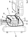
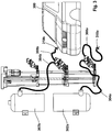
- FIGS. 1 to 4 show four different embodiments of a device according to the invention for filling a tank of a motor vehicle with a device for initial industrial filling on the assembly line of the manufacturer.
- the device moves along with the assembly line and the motor vehicle along the assembly line until the motor vehicle 100 is fully refueled accordingly. Subsequently, the device is moved back to the starting point and filled the next motor vehicle of this assembly line. The means necessary for moving back are not shown here.
- the first embodiment illustrated comprises a storage tank 102 with the desired operating means, which is connected via a supply line 104 with a pump 106.
- a tank hose 108 is connected, at its free end a filling adapter 110 is provided, which is insertable into the tank of the motor vehicle 100, not shown here.
- the pump 106 is formed of a hollow cylinder 112 with a piston 114 held coaxially displaceable therein, with a piston rod 116 attached to the piston 114.
- This piston rod 116 is provided with a drive 118 to axially move the piston 114 within the hollow cylinder 112.
- the drive 118 is designed as an electrically driven servomotor which moves the piston rod 116 formed as a spindle via a gear not shown in detail here such that the piston 114 is moved within the hollow cylinder 112 up and down.
- the drive of the piston rod is also hydraulically or pneumatically.
- both an exhaust valve, not shown here, and an intake valve, not shown here, are provided, wherein the tank hose 108 is attached to the exhaust valve while the supply pipe 104 is attached to the intake valve.
- the first embodiment of the device according to the invention means for accurately determining the current position of the piston 114 is provided.
- This can be, for example, a displacement transducer.
- the piston 114 is brought via the drive 118 into its basic position at the upper end of the hollow cylinder 112, so that the maximum volume is available in the hollow cylinder 112.
- the desired operating medium is brought from the storage tank 102 via the supply line 104 and the now opened inlet valve into the hollow cylinder 112 of the pump 106.
- the inlet valve is closed and now the device for filling a tank of a motor vehicle is ready.
- the filling adapter 110 is introduced into the tank of the motor vehicle 100 and then the piston 114 is guided downwards via the piston ends 116 and the drive 118. Meanwhile, the entire device is carried along with the motor vehicle 100 parallel to the assembly line.
- the drive 118 knows how far the piston 114 within the hollow cylinder 112 must be guided down to fill the desired amount of the resource from the hollow cylinder 112 via the tank tube 108 and the filling adapter 110 in the tank. After the piston 114 has returned to the predetermined path and thus has reached its end position, the drive 118 is stopped, so that the piston 114 remains in the corresponding position. Now exactly the predetermined of the equipment has entered the tank of the motor vehicle.
- the Be Scholladapter 110 is withdrawn from the tank of the motor vehicle 100 and the entire device is returned to the starting position, wherein the piston 114 is returned by the drive 118 back to its original position and the hollow cylinder 112 is completely filled with the resources before the process begins again with the next motor vehicle 100.
- a first operating medium chamber 222 in the region in front of the piston 214 and a second operating fluid chamber 224 in the region behind the piston 214 are formed in the hollow cylinder 212.
- a wall 228 for limiting the second operating medium chamber 224 is provided on a second end face 226, in which also an inlet valve, not shown here in detail, and an outlet valve, not shown here, is integrated. It is understood that in the wall 228 an opening for the passage of the piston rod 216 is provided.
- the supply line 204 is Y-shaped and leads from the storage tank 202 via the first end face 220 in the first resource chamber 222 and via the wall 228 in the second Stinseite 226 in the second resource chamber 224.
- the tank line 208 is also Y-shaped and connected to both the first resource chamber 222, and to the second resource chamber 224, but has only a filling adapter 210.
- FIG. 3 illustrated third embodiment differs from the in FIG. 2 illustrated second embodiment only in that two separate storage tanks 302a and 302b, two separate supply lines 304a and 304b, and two separate Tankschlumblee 308a and 308b including two separate filling adapters 310a and 310b are provided.
- the second and third embodiments are identical. With this third embodiment, it is possible during a cycle of the assembly line to fill two different resources in two different tanks of the motor vehicle 300, without significantly increasing the apparatus construction for this purpose.
- FIG. 4 Illustrated fourth embodiment is identical to that in FIG. 1 illustrated first embodiment, but additionally has a water-filled surge tank 430, which is connected via a attached to the second end face 426 of the hollow cylinder 412 connecting line 432 with the part of the hollow cylinder 412 behind the piston 414.
- the hollow cylinder 412 is in the region of the back of the Piston 414 always filled with water.
- the piston 414 presses this water during startup back into the expansion tank 430 and when shutting down water from the expansion tank 430 enters the hollow cylinder 412, so that always sufficient water covers the piston 414 and the inner wall of the hollow cylinder 412, so that there is not adhering urea crystallized.
Landscapes
- Engineering & Computer Science (AREA)
- Mechanical Engineering (AREA)
- General Engineering & Computer Science (AREA)
- Filling Or Discharging Of Gas Storage Vessels (AREA)
Applications Claiming Priority (1)
| Application Number | Priority Date | Filing Date | Title |
|---|---|---|---|
| DE102016005319.4A DE102016005319A1 (de) | 2016-05-02 | 2016-05-02 | Vorrichtung zum Befüllen eines Tanks eines Kraftfahrzeuges mit einem flüssigen oder gasförmigen Betriebsmittel, insbesondere zur industriellen Erstbefüllung am Montageband des Herstellers |
Publications (1)
| Publication Number | Publication Date |
|---|---|
| EP3242016A1 true EP3242016A1 (fr) | 2017-11-08 |
Family
ID=58644954
Family Applications (1)
| Application Number | Title | Priority Date | Filing Date |
|---|---|---|---|
| EP17168732.0A Withdrawn EP3242016A1 (fr) | 2016-05-02 | 2017-04-28 | Dispositif de remplissage d'un réservoir de véhicule automobile en carburant gazeux ou liquide, en particulier pour le premier remplissage industriel sur une chaîne de fabrication du fabricant |
Country Status (2)
| Country | Link |
|---|---|
| EP (1) | EP3242016A1 (fr) |
| DE (1) | DE102016005319A1 (fr) |
Citations (8)
| Publication number | Priority date | Publication date | Assignee | Title |
|---|---|---|---|---|
| CH399908A (de) * | 1960-08-08 | 1965-09-30 | Schwing Friedrich Wilh | Hydraulische Kolbenpumpe zur Förderung dickflüssiger, breiiger oder plastischer Massen |
| US3456595A (en) * | 1966-09-20 | 1969-07-22 | Union Carbide Corp | Cryogenic liquid metering pump |
| US3538961A (en) * | 1968-08-23 | 1970-11-10 | Ralph E Bruce | Refrigeration system servicing unit with dispensing pump and connector |
| WO1996008648A1 (fr) * | 1994-09-14 | 1996-03-21 | Wallace & Tiernan, Inc. | Systeme de commande de pompe de dosage |
| US20070286745A1 (en) * | 2006-06-09 | 2007-12-13 | Maynard Chance | Integrated mixing pump |
| US20130039778A1 (en) * | 2009-12-08 | 2013-02-14 | Graco Minnesota Inc. | System and method for controlling linear pump system |
| US20140377110A1 (en) * | 2011-12-27 | 2014-12-25 | Nuovo Pignone S.P.A. | Devices and methods for actuating valves |
| DE102014011051A1 (de) | 2014-07-22 | 2016-01-28 | Dürr Somac GmbH | Vorrichtung zur Befüllung von Fahrzeugklimasystemen mit Kältemittel R744 |
Family Cites Families (4)
| Publication number | Priority date | Publication date | Assignee | Title |
|---|---|---|---|---|
| SE8105988L (sv) * | 1981-10-09 | 1983-04-10 | Hk Eng Ab | Pump av deplacementtyp |
| DE4028734A1 (de) * | 1990-09-10 | 1992-03-12 | Tecalemit Gmbh Deutsche | System zur eichgerechten abgabe von fluiden fuer kraftfahrzeuge |
| US5297399A (en) * | 1992-09-24 | 1994-03-29 | Tieken James B | Manually operated refrigerant recovery device |
| IT1398766B1 (it) * | 2010-03-03 | 2013-03-18 | Brain Bee Holding S P A | Dispositivo di manutenzione per impianti di condizionamento. |
-
2016
- 2016-05-02 DE DE102016005319.4A patent/DE102016005319A1/de not_active Withdrawn
-
2017
- 2017-04-28 EP EP17168732.0A patent/EP3242016A1/fr not_active Withdrawn
Patent Citations (8)
| Publication number | Priority date | Publication date | Assignee | Title |
|---|---|---|---|---|
| CH399908A (de) * | 1960-08-08 | 1965-09-30 | Schwing Friedrich Wilh | Hydraulische Kolbenpumpe zur Förderung dickflüssiger, breiiger oder plastischer Massen |
| US3456595A (en) * | 1966-09-20 | 1969-07-22 | Union Carbide Corp | Cryogenic liquid metering pump |
| US3538961A (en) * | 1968-08-23 | 1970-11-10 | Ralph E Bruce | Refrigeration system servicing unit with dispensing pump and connector |
| WO1996008648A1 (fr) * | 1994-09-14 | 1996-03-21 | Wallace & Tiernan, Inc. | Systeme de commande de pompe de dosage |
| US20070286745A1 (en) * | 2006-06-09 | 2007-12-13 | Maynard Chance | Integrated mixing pump |
| US20130039778A1 (en) * | 2009-12-08 | 2013-02-14 | Graco Minnesota Inc. | System and method for controlling linear pump system |
| US20140377110A1 (en) * | 2011-12-27 | 2014-12-25 | Nuovo Pignone S.P.A. | Devices and methods for actuating valves |
| DE102014011051A1 (de) | 2014-07-22 | 2016-01-28 | Dürr Somac GmbH | Vorrichtung zur Befüllung von Fahrzeugklimasystemen mit Kältemittel R744 |
Also Published As
| Publication number | Publication date |
|---|---|
| DE102016005319A1 (de) | 2017-11-02 |
Similar Documents
| Publication | Publication Date | Title |
|---|---|---|
| DE19652120A1 (de) | Benzindampfrückgewinnungsvorrichtung und -verfahren | |
| EP4132722B1 (fr) | Pompe à agent de revêtement, installation de revêtement et procédé de fonctionnement associé | |
| DE3127831A1 (de) | "system und vorrichtung zum pumpen" | |
| DE102014209101A1 (de) | Dosiereinrichtung zum dosierten Ausbringen eines Schmierfetts auf eine Fläche, Verfahren zum dosierten Ausbringen eines Schmierfetts auf eine Fläche | |
| DE2002730A1 (de) | Dosiereinrichtung | |
| EP3262300B1 (fr) | Procédé pour opérer un dispositif pour la fourniture dosée d'un liquide | |
| DE102005033467B4 (de) | Verbesserte Getriebepumpe und Filter | |
| EP2989328B1 (fr) | Pompe pour doser un additifliquide d'un dispositif de réduction sélective catalytique | |
| EP3317060A1 (fr) | Dispositif de mélange pour le mélange d'un composant liquide d'un matériau synthétique avec un gaz | |
| DE69724431T2 (de) | Befüllvorrichtung | |
| EP2989306B1 (fr) | Procédé de mise en oeuvre d'un dispositif de dosage d'un liquide | |
| DE102013018281A1 (de) | Volumetrische Dosiereinheit | |
| EP3757060B1 (fr) | Installation de distribution du liquide d'un véhicule citerne contenant plusieurs chambres | |
| WO2009083003A1 (fr) | Adaptateur pour le remplissage de véhicules avec du carburant | |
| DE2402837A1 (de) | Schmiersystem fuer den zweitakt-verbrennungsmotor | |
| EP3242016A1 (fr) | Dispositif de remplissage d'un réservoir de véhicule automobile en carburant gazeux ou liquide, en particulier pour le premier remplissage industriel sur une chaîne de fabrication du fabricant | |
| DE2229370A1 (de) | Kolbenpumpe, insbesondere Meßpumpe für Stoffe mit niedriger, mittlerer oder hoher Viskosität, einschließlich thixotrope Stoffe | |
| EP3861416B1 (fr) | Système d'éjection de liquide pour une installation de lavage de véhicules et son procédé de fonctionnement | |
| DE3742591A1 (de) | Fluessigkeits-spender | |
| DE3026994C2 (de) | Vorrichtung zum Flüssigkeitswechsel, insbesondere bei Kraftfahrzeugen | |
| DE10229261C1 (de) | Verfahren und Vorrichtung zum Dosieren eines als Aufschäummittel dienenden Fluids in eine Schmelzekammer einer Kunststoffverarbeitungsmaschine | |
| EP3861417B1 (fr) | Système d'éjection de liquide pour une installation de lavage de véhicules et son procédé de fonctionnement | |
| DE2318390C3 (de) | Hydrostatisch angetriebene Kolbenpumpe | |
| DE202010018055U1 (de) | Dosiervorrichtung für einen scherempfindlichen Klebstoff sowie Vorrichtung zur Aufbringung von Klebstoff mit einer derartigen Dosiervorrichtung | |
| DE1013522B (de) | Als Membranpumpe ausgebildete Dosierpumpe zur Foerderung hochexplosiver Fluessigkeiten |
Legal Events
| Date | Code | Title | Description |
|---|---|---|---|
| PUAI | Public reference made under article 153(3) epc to a published international application that has entered the european phase |
Free format text: ORIGINAL CODE: 0009012 |
|
| STAA | Information on the status of an ep patent application or granted ep patent |
Free format text: STATUS: THE APPLICATION HAS BEEN PUBLISHED |
|
| STAA | Information on the status of an ep patent application or granted ep patent |
Free format text: STATUS: REQUEST FOR EXAMINATION WAS MADE |
|
| AK | Designated contracting states |
Kind code of ref document: A1 Designated state(s): AL AT BE BG CH CY CZ DE DK EE ES FI FR GB GR HR HU IE IS IT LI LT LU LV MC MK MT NL NO PL PT RO RS SE SI SK SM TR |
|
| AX | Request for extension of the european patent |
Extension state: BA ME |
|
| 17P | Request for examination filed |
Effective date: 20171030 |
|
| RBV | Designated contracting states (corrected) |
Designated state(s): AL AT BE BG CH CY CZ DE DK EE ES FI FR GB GR HR HU IE IS IT LI LT LU LV MC MK MT NL NO PL PT RO RS SE SI SK SM TR |
|
| 19U | Interruption of proceedings before grant |
Effective date: 20180501 |
|
| 19W | Proceedings resumed before grant after interruption of proceedings |
Effective date: 20190801 |
|
| STAA | Information on the status of an ep patent application or granted ep patent |
Free format text: STATUS: THE APPLICATION IS DEEMED TO BE WITHDRAWN |
|
| 18D | Application deemed to be withdrawn |
Effective date: 20200204 |