EP4132722B1 - Pompe à agent de revêtement, installation de revêtement et procédé de fonctionnement associé - Google Patents
Pompe à agent de revêtement, installation de revêtement et procédé de fonctionnement associé Download PDFInfo
- Publication number
- EP4132722B1 EP4132722B1 EP21718058.7A EP21718058A EP4132722B1 EP 4132722 B1 EP4132722 B1 EP 4132722B1 EP 21718058 A EP21718058 A EP 21718058A EP 4132722 B1 EP4132722 B1 EP 4132722B1
- Authority
- EP
- European Patent Office
- Prior art keywords
- coating agent
- pump
- blow
- line
- compressed air
- Prior art date
- Legal status (The legal status is an assumption and is not a legal conclusion. Google has not performed a legal analysis and makes no representation as to the accuracy of the status listed.)
- Active
Links
Images


Classifications
-
- B—PERFORMING OPERATIONS; TRANSPORTING
- B05—SPRAYING OR ATOMISING IN GENERAL; APPLYING FLUENT MATERIALS TO SURFACES, IN GENERAL
- B05B—SPRAYING APPARATUS; ATOMISING APPARATUS; NOZZLES
- B05B12/00—Arrangements for controlling delivery; Arrangements for controlling the spray area
- B05B12/14—Arrangements for controlling delivery; Arrangements for controlling the spray area for supplying a selected one of a plurality of liquids or other fluent materials or several in selected proportions to a spray apparatus, e.g. to a single spray outlet
- B05B12/1481—Arrangements for controlling delivery; Arrangements for controlling the spray area for supplying a selected one of a plurality of liquids or other fluent materials or several in selected proportions to a spray apparatus, e.g. to a single spray outlet comprising pigs, i.e. movable elements sealingly received in supply pipes, for separating different fluids, e.g. liquid coating materials from solvent or air
-
- B—PERFORMING OPERATIONS; TRANSPORTING
- B05—SPRAYING OR ATOMISING IN GENERAL; APPLYING FLUENT MATERIALS TO SURFACES, IN GENERAL
- B05B—SPRAYING APPARATUS; ATOMISING APPARATUS; NOZZLES
- B05B15/00—Details of spraying plant or spraying apparatus not otherwise provided for; Accessories
- B05B15/50—Arrangements for cleaning; Arrangements for preventing deposits, drying-out or blockage; Arrangements for detecting improper discharge caused by the presence of foreign matter
- B05B15/55—Arrangements for cleaning; Arrangements for preventing deposits, drying-out or blockage; Arrangements for detecting improper discharge caused by the presence of foreign matter using cleaning fluids
-
- B—PERFORMING OPERATIONS; TRANSPORTING
- B05—SPRAYING OR ATOMISING IN GENERAL; APPLYING FLUENT MATERIALS TO SURFACES, IN GENERAL
- B05B—SPRAYING APPARATUS; ATOMISING APPARATUS; NOZZLES
- B05B15/00—Details of spraying plant or spraying apparatus not otherwise provided for; Accessories
- B05B15/50—Arrangements for cleaning; Arrangements for preventing deposits, drying-out or blockage; Arrangements for detecting improper discharge caused by the presence of foreign matter
- B05B15/58—Arrangements for cleaning; Arrangements for preventing deposits, drying-out or blockage; Arrangements for detecting improper discharge caused by the presence of foreign matter preventing deposits, drying-out or blockage by recirculating the fluid to be sprayed from upstream of the discharge opening back to the supplying means
-
- B—PERFORMING OPERATIONS; TRANSPORTING
- B05—SPRAYING OR ATOMISING IN GENERAL; APPLYING FLUENT MATERIALS TO SURFACES, IN GENERAL
- B05B—SPRAYING APPARATUS; ATOMISING APPARATUS; NOZZLES
- B05B9/00—Spraying apparatus for discharge of liquids or other fluent material, without essentially mixing with gas or vapour
- B05B9/03—Spraying apparatus for discharge of liquids or other fluent material, without essentially mixing with gas or vapour characterised by means for supplying liquid or other fluent material
- B05B9/04—Spraying apparatus for discharge of liquids or other fluent material, without essentially mixing with gas or vapour characterised by means for supplying liquid or other fluent material with pressurised or compressible container; with pump
- B05B9/0403—Spraying apparatus for discharge of liquids or other fluent material, without essentially mixing with gas or vapour characterised by means for supplying liquid or other fluent material with pressurised or compressible container; with pump with pumps for liquids or other fluent material
- B05B9/0409—Spraying apparatus for discharge of liquids or other fluent material, without essentially mixing with gas or vapour characterised by means for supplying liquid or other fluent material with pressurised or compressible container; with pump with pumps for liquids or other fluent material the pumps being driven by a hydraulic or a pneumatic fluid
-
- F—MECHANICAL ENGINEERING; LIGHTING; HEATING; WEAPONS; BLASTING
- F04—POSITIVE - DISPLACEMENT MACHINES FOR LIQUIDS; PUMPS FOR LIQUIDS OR ELASTIC FLUIDS
- F04B—POSITIVE-DISPLACEMENT MACHINES FOR LIQUIDS; PUMPS
- F04B23/00—Pumping installations or systems
- F04B23/02—Pumping installations or systems having reservoirs
-
- F—MECHANICAL ENGINEERING; LIGHTING; HEATING; WEAPONS; BLASTING
- F04—POSITIVE - DISPLACEMENT MACHINES FOR LIQUIDS; PUMPS FOR LIQUIDS OR ELASTIC FLUIDS
- F04B—POSITIVE-DISPLACEMENT MACHINES FOR LIQUIDS; PUMPS
- F04B43/00—Machines, pumps, or pumping installations having flexible working members
- F04B43/02—Machines, pumps, or pumping installations having flexible working members having plate-like flexible members, e.g. diaphragms
- F04B43/025—Machines, pumps, or pumping installations having flexible working members having plate-like flexible members, e.g. diaphragms two or more plate-like pumping members in parallel
- F04B43/026—Machines, pumps, or pumping installations having flexible working members having plate-like flexible members, e.g. diaphragms two or more plate-like pumping members in parallel each plate-like pumping flexible member working in its own pumping chamber
-
- F—MECHANICAL ENGINEERING; LIGHTING; HEATING; WEAPONS; BLASTING
- F04—POSITIVE - DISPLACEMENT MACHINES FOR LIQUIDS; PUMPS FOR LIQUIDS OR ELASTIC FLUIDS
- F04B—POSITIVE-DISPLACEMENT MACHINES FOR LIQUIDS; PUMPS
- F04B43/00—Machines, pumps, or pumping installations having flexible working members
- F04B43/02—Machines, pumps, or pumping installations having flexible working members having plate-like flexible members, e.g. diaphragms
- F04B43/06—Pumps having fluid drive
Definitions
- the invention relates to a coating agent pump for conveying a coating agent (e.g. paint) in a coating system, in particular in a painting system for painting motor vehicle body components.
- a coating agent e.g. paint
- the invention also includes a corresponding coating system and an associated operating method.
- Figure 1 shows a schematic representation of a conventional coating system, which can be used, for example, for painting vehicle body components.
- This known coating system has a pigging station 1, which supplies an applicator (e.g. rotary atomizer) with coating agent via several piggable supply lines 2.
- an applicator e.g. rotary atomizer
- Several central lines 3 run through the pigging station 1, whereby only three central lines 3 are shown as an example in the drawing.
- Different colored coating agents can be supplied via the central lines 3.
- the middle central line 3 of the pigging station 1 is connected via a pressure line 4 to a coating agent pump 5, as shown for example in DE 10 2013 003 620 A1 is known.
- the coating agent pump 5 sucks in the coating agent to be applied via a suction line 6 from a paint supply 7, which is only shown schematically here and has a coating agent container.
- the other two central lines 3 of the pigging station 1 are supplied in the same way via pressure lines, but this is not shown here for the sake of simplicity.
- the pigging station 1 has a circulation module 8 with circulation connections 9 and circulation valves (not shown).
- a circulation line 10 is connected to the circulation connections 9, which leads back to the paint supply 7 and enables circulation operation.
- the circulation valves of the circulation module 8 make it possible to optionally connect the central lines 3 of the pigging station 1 with the circulation line 10.
- the pigging station 1 contains a return module 11 with return connections 12 and return valves (not shown).
- the return module 11 is connected to a return line 13, which leads to a dirt thinner receptacle 14 and enables the return of residues of coating agent and rinsing agent.
- the coating agent pump 5 for example, according to the published patent application DE 10 2013 003 620 A1 This means, among other things, that the coating agent pump 5 is driven pneumatically. For this purpose, a control line 15 leads into the coating agent pump 5.
- a blow-out line 16 leads into the coating agent pump via a blow-out valve 17 designed as a check valve, as already shown in DE 10 2013 003 620 A1 is known.
- the pressure line 4 and the circulation line 10 When changing the color, the pressure line 4 and the circulation line 10 must be blown out and rinsed out over their entire length. This means that high color change losses occur when changing the color, since only a small amount of coating agent can be recovered. In addition, a color change also requires a large amount of rinsing agent when rinsing the pressure line 4 and the circulation line 10.
- the coating agent pump 5 and the pressure line 4 must then be pressed (i.e. filled) with the new coating agent.
- This pressing with the new coating agent requires a certain pressing time depending on the length of the pressure line 4 and the viscosity of the coating agent.
- the components of the coating system are then rinsed, for which larger quantities of rinsing agent are required due to the arrangement of the pressure line 4 and the circulation line 10.
- solvent rinsing agent
- several pump strokes of, for example, 3-6 pump strokes are required, which leads to an additional loss of coating agent, such as 75 ml per pump stroke.
- the pressure line 4 and the circulation line 10 When changing the color, the pressure line 4 and the circulation line 10 must be completely filled with coating agent. However, the circulation line 10 can only be filled via the pigging station 1. This results in correspondingly long lines with an increased line volume and corresponding losses of coating agent.
- the residual emptying and blow-out function of the coating agent pump 5 empty the pressure line 4 and the circulation line 10.
- a high proportion of the coating agent remains in the lines. For example, 20% of the coating agent can still remain in the pressure line 4, while as much as 80% of the coating agent can still remain in the circulation line 10.
- a residual amount of the rinsing agent remains in the coating agent pump 5 during a rinsing process, since the arrangement of the components of the coating system makes it impossible to completely remove the rinsing agent from the coating agent pump 5. This means that the remaining rinsing agent must be pressed into the return line 13 with the newly pressed coating agent. This increases the loss of coating agent to push the rinsing agent back into the return line 13 when filling with the new coating agent.
- the pressing time required for pressing a new coating agent depends on the viscosity of the coating agent.
- the coating agent losses when pressing a new coating agent also depend on the viscosity of the previous coating agent.
- the invention is therefore based on the object of creating a correspondingly improved coating agent pump, a correspondingly improved coating system and an associated operating method.
- the invention initially comprises a coating agent pump, which is partially identical to the known coating agent pump described above according to DE 10 2013 003 620 A1 so that, in order to avoid repetition, reference is also made to this publication.
- the coating agent pump according to the invention is generally suitable for conveying a coating agent, such as a paint.
- a coating agent such as a paint.
- the invention is not limited to paints with regard to the type of coating agent to be conveyed, but can in principle also be implemented with other types of coating agents.
- the coating agent pump according to the invention is preferably adapted for use in a painting system for painting motor vehicle body components.
- the coating agent pump according to the invention can also be used in principle in other systems for conveying coating agents.
- the coating agent pump according to the invention has, in accordance with the known coating agent pump described at the outset, DE 10 2013 003 620 A1 a pump inlet to which the coating agent to be pumped is supplied.
- the pump inlet of the coating agent pump can be connected to a paint supply via a suction line.
- the pump inlet of the coating agent pump according to the invention opens into an inlet area within the coating agent pump, which is fed with the coating agent from the pump inlet.
- the coating agent pump according to the invention has, in accordance with the known coating agent pump described at the outset, DE 10 2013 003 620 A1 a pump outlet at which the coating agent to be pumped is dispensed.
- the pressure line described at the beginning can be connected to the pump outlet.
- the coating agent pump according to the invention corresponds in this respect to the known coating agent pump described at the beginning according to DE 10 2013 003 620 A1
- the invention is based on the realization that the problems of the known coating system described above arise from the fact that the circulation line starts from the pigging station, since in this way, when the color is changed, the pressure line and the circulation line must be flushed, blown out and filled with new coating agent over their entire length.
- the coating agent pump according to the invention is therefore characterized by an outlet-side circulation connection to which the circulation line can be connected in order to return coating agent to a paint supply when changing color.
- the circulation connection of the coating agent pump is provided in addition to the pump inlet and the pump outlet.
- the coating agent pump according to the invention therefore has at least one further additional connection in addition to the pump inlet and the pump outlet with the circulation connection. This circulation connection is connected to the outlet area of the coating agent pump and is fed with the coating agent to be returned from the outlet area of the coating agent pump.
- the coating agent pump according to the invention preferably has a controllable circulation valve integrated into the coating agent pump in order to control the coating agent flow from the outlet region of the coating agent pump through the circulation connection into the circulation line.
- This design of the coating agent pump according to the invention allows the circulation line to branch off far upstream of the pigging station, namely directly from the coating agent pump. This offers the advantage that the circulation line is relatively short, which leads to correspondingly low color change losses. In this way, the line lengths can be shortened by 50-90%, which leads to a correspondingly large reduction in coating agent losses.
- the coating agent pump additionally has a return connection on the outlet side, which allows residues of the coating agent and/or a rinsing agent to be returned to a return line, which leads into a dirt thinner receptacle
- This return connection is provided in addition to the pump outlet, the pump inlet and the circulation connection and is connected to the outlet area of the coating agent pump. The return connection of the coating agent pump is therefore fed with the coating agent or rinsing agent to be returned from the outlet area of the coating agent pump.
- the return connection preferably has a controllable return valve integrated into the coating agent pump in order to control the flow of coating agent from the outlet region of the coating agent pump through the return connection into the return line to the dirt thinner receptacle.
- controllable valve used in the context of the invention is to be distinguished from valves that are actuated by their own medium, such as check valves, in which the valve position is determined by the pressure at the inlet and outlet of the valve.
- controllable valves can be controlled electromagnetically or pneumatically, as is known per se from the prior art.
- the coating agent pump according to the invention can basically be constructed similarly to that of DE 10 2013 003 620 A1 known coating agent pump.
- the coating agent pump according to the invention is preferably a positive displacement pump, which can be designed, for example, as a diaphragm pump and preferably as a double diaphragm pump.
- the coating agent pump according to the invention preferably has a pump chamber, wherein the inlet region and the outlet region of the coating agent pump are connected to the pump chamber.
- a movable displacer for example in the form of a membrane, as can be seen from DE 10 2013 003 620 A1 is known.
- the coating agent pump according to the invention comprises a drive for moving the displacer (e.g. membrane) for pumping the coating agent.
- this drive can be designed as a pneumatic or electric drive.
- an inlet valve integrated into the coating agent pump, which is preferably designed as a check valve and releases a coating agent flow from the inlet area into the pump chamber, whereas an oppositely directed coating agent flow from the pump chamber into the inlet area is blocked by the check valve.
- a check valve preferably has a tension spring, a valve body (e.g. valve ball) and a valve seat, wherein the tension spring presses the valve body sealingly into the valve seat in a closed position.
- the coating agent pump according to the invention preferably has an outlet valve integrated into the coating agent pump between the pump chamber and the pump outlet, wherein the outlet valve is also preferably designed as a check valve.
- This check valve also preferably has a tension spring, a valve body (e.g. valve ball) and a valve seat, wherein the tension spring presses the valve body sealingly into the valve seat in a closed position.
- the coating agent pump according to the invention preferably has a first blow-out connection, which serves to blow out the pump chamber with compressed air.
- the first blow-out connection therefore preferably opens into the pump chamber, as is already apparent from DE 10 2013 003 620 A1 is known.
- the first blow-out connection opens into the pump chamber via the inlet valve designed as a check valve.
- the coating agent flows in a certain predetermined flow direction through the inlet valve from the inlet area through the inlet valve into the pump chamber of the coating agent pump.
- the first blow-out connection preferably opens into the inlet valve downstream behind the valve seat. This means that the pump chamber can be blown out via the first blow-out connection while the inlet valve is closed.
- the first blow-out connection is associated with a first blow-out valve, which is preferably integrated into the coating agent pump and, when blowing out, directs the compressed air flow through the first blow-out connection into the pump chamber controls.
- This first blow-out valve is preferably designed as a check valve that releases a compressed air flow through the first blow-out connection into the pump chamber and blocks an opposing compressed air flow from the pump chamber through the first blow-out connection.
- the first blow-out valve it is alternatively also possible for the first blow-out valve to be designed as a controllable valve, so that the valve position of the first blow-out valve can then be controlled independently of the pressure conditions at the inlet and outlet of the first blow-out valve.
- the coating agent pump preferably also has a second blow-out connection on the inlet side in order to blow coating agent out of the inlet area of the coating agent pump using compressed air.
- the coating agent in the inlet area of the coating agent pump can thus be blown back through the pump inlet to the paint supply by supplying compressed air through the second blow-out connection on the inlet side.
- the second blow-out connection is assigned a controllable second blow-out valve, which is preferably integrated into the coating agent pump and controls the compressed air flow through the second blow-out connection into the inlet area of the coating agent pump.
- the coating agent pump is designed as a double diaphragm pump and thus has two pump chambers, two inlet valves, two outlet valves and two movably driven diaphragms, each of which is arranged in one of the two pump chambers. Two of the first blow-out connections can then be provided in order to blow out one of the two pump chambers.
- the two housing covers are preferably cast parts, preferably made of stainless steel.
- the invention also comprises a coating system which also contains an optimized arrangement of the circulation line.
- the coating system according to the invention initially has, in accordance with the known coating systems, a paint supply which provides the coating agent to be applied and contains, for example, a coating agent container.
- the coating system according to the invention also has a coating agent pump to convey the coating agent from the paint supply in the direction of the applicators.
- the coating agent pump is designed in the manner according to the invention described above.
- the coating agent pump feeds a pressure line that originates from the coating agent pump.
- the coating system according to the invention comprises a removal point that is connected to the pressure line and is fed with the coating agent from the pressure line.
- the coating agent flows in a predetermined flow direction from the coating agent pump through the pressure line to the removal point.
- the extraction point is designed as a pigging station and feeds at least one piggable supply line that starts from the pigging station and leads to an application device that applies the coating agent.
- the coating system according to the invention also comprises a circulation line, which back to the paint supply and enables recovery of coating agent during a rinsing process.
- the coating system according to the invention is now characterized by a new arrangement of the circulation line, which no longer starts from the extraction point, but branches off upstream of the extraction point in relation to the normal flow direction in the coating operation.
- This reflects the same inventive idea as in the coating agent pump according to the invention described at the beginning, in which the circulation line branches off directly from the coating agent pump. In both cases (branching of the circulation line directly from the coating agent pump or from the pressure line), the length of the circulation line is shortened, which reduces the losses when changing color.
- the circulation line preferably opens directly from the circulation connection of the coating agent pump.
- the circulation line branches off from the pressure line at a branch point between the extraction point and the coating agent pump.
- controllable circulation valve in the circulation line for controlling the flow of coating agent through the circulation line. If the circulation line branches off directly from the coating agent pump, this circulation valve is preferably also integrated into the coating agent pump. Otherwise, the controllable circulation valve is separate from the coating agent pump.
- the coating system according to the invention preferably also has a dirt thinner receptacle, as is known per se from the prior art and serves to collect and dispose of residues of the coating agent and a rinsing agent.
- This dirt thinner receptacle is preferably fed by a first return line that leads to the dirt thinner receptacle.
- this first return line can be from an outlet-side Return connection of the coating agent pump, as already mentioned above in the description of the coating agent pump according to the invention.
- the coating system according to the invention preferably also has a second return line which leads from the removal point to the dirt thinner receptacle.
- the coating system according to the invention can therefore have two return lines, wherein the first return line branches off upstream of the removal point, for example directly from an outlet-side return connection of the coating agent pump, while the second return line starts from the removal point.
- a controllable return valve is preferably provided in the first return line to control the fluid flow through the first return line into the dirt thinner receptacle. This return valve is preferably integrated into the coating agent pump.
- This first blow-out connection preferably opens into the pump chamber in the coating agent pump via the inlet valve designed as a check valve. It is advantageous if the compressed air supplied via the first blow-out connection pushes the valve body of the inlet valve designed as a check valve into the closed position. The compressed air supplied via the first blow-out connection then contributes to closing the inlet valve and reaches the pump chamber in order to blow it out. It is advantageous if the coating agent pump has at least one first blow-out valve in order to control the compressed air flow through the first blow-out connection into the pump chamber.
- This first blow-out valve can, for example, be designed as a check valve which releases a compressed air flow through the first blow-out connection into the pump chamber, whereas an oppositely directed compressed air flow from the pump chamber through the first blow-out connection is blocked.
- a first blow-out line is preferably connected to the first blow-out connection of the coating agent pump in order to blow in compressed air.
- the coating agent pump according to the invention can have a second blow-out connection on the inlet side in order to blow coating agent out of the inlet area of the coating agent pump, whereby the coating agent located therein can then be returned to the paint supply through the pump inlet.
- the compressed air flow through the second blow-out connection is preferably controlled by a second blow-out valve, as already described above.
- the arrangement of the circulation line according to the invention enables a relatively short line length for the circulation line, which is associated with correspondingly low coating agent losses.
- the circulation line can have a line length of at most 2m, 1m, 50cm or 25cm.
- the coating agent pump is preferably driven pneumatically with compressed air, the compressed air having a certain drive air pressure, while the coating agent is conveyed with a certain delivery pressure.
- the coating agent pump preferably enables a transmission ratio between the delivery pressure and the drive air pressure, this transmission ratio being able to be at least 2:1, 3:1 or 4:1, for example.
- the coating agent pump according to the invention is preferably a diaphragm pump, such as a double diaphragm pump.
- the invention is not limited to diaphragm pumps with regard to the type of coating agent pump.
- the coating agent pump according to the invention preferably has at least one pneumatically driven drive piston, wherein in the case of a double diaphragm pump two drive pistons can be provided.
- the extraction point can be designed, for example, as a pigging station and can feed several supply lines, each of which leads to an application device (e.g. rotary atomizer) and supplies the respective application device with the coating agent to be applied.
- an application device e.g. rotary atomizer
- the extraction point can have at least one compressed air connection and at least one controllable compressed air valve in order to be able to feed compressed air into the pressure line at the extraction point.
- the compressed air is preferably also fed in as pulsed air.
- the extraction point can have a compressed air module that has several compressed air connections and several compressed air valves for the various central lines of the extraction point.
- the extraction point can have a return connection for connecting the second return line and a controllable return valve for controlling the return.
- the extraction point can have a return module that has several return connections and several return valves for the various central lines of the extraction point.
- the extraction point can therefore have several central channels, each of which is fed with the coating agent from a pressure line, as already briefly described above.
- the invention also comprises an associated operating method.
- the circulation valve is opened, among other things, in order to be able to return coating agent residues to the paint supply through the circulation line.
- compressed air e.g. pulsed air
- the coating agent in the pressure line is then pushed back along the pressure line using compressed air and then passes through the opened circulation valve through the circulation line back to the paint supply.
- the return valve of the first return line can be opened, which either comes directly from the coating agent pump or between the coating agent pump and the extraction point branches off.
- compressed air e.g. pulsed air
- the return valve of the first return line can be opened, which either comes directly from the coating agent pump or between the coating agent pump and the extraction point branches off.
- compressed air e.g. pulsed air
- residual quantities of rinsing agent and/or coating agent from the pressure line and/or from the outlet area of the coating agent pump are pressed by means of the compressed air through the first return line into the dirt thinner receptacle.
- these processes are carried out one after the other.
- the coating agent in the pressure line is preferably fed back into the paint supply via the circulation line. Subsequently, any residues of the coating agent and, if applicable, rinsing agent are transferred from the pressure line to the dirt thinner receptacle via the first return line.
- coating agent residues can remain in the pump chamber of the coating agent pump during a rinsing process. These coating agent residues can also be at least partially recovered as part of the operating method according to the invention.
- the circulation valve is opened to enable the coating agent residues to be returned through the circulation line to the paint supply.
- Compressed air e.g. pulsed air
- the coating agent in the coating agent pump is then pressed back into the paint supply through the circulation line using the supplied compressed air.
- coating agent residues can also remain in the inlet area of the coating agent pump.
- these coating agent residues can also be at least partially recovered.
- compressed air is blown through the second blow-out line into the second blow-out connection of the coating agent pump and from there reaches the inlet area of the coating agent pump.
- the coating agent in the inlet area of the coating agent pump can thus be pressed through the pump inlet back to the paint supply by means of the supplied compressed air.
- the pressure line can be flowed through bidirectionally.
- the respective coating agent flows from the coating agent pump through the pressure line to the extraction point, from where the coating agent then finally reaches the applicators.
- the coating agent flows in the opposite direction from the extraction point back to the coating agent pump and from there through the circulation line back to the paint supply.
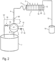
- a special feature of the coating system according to the invention Figure 2 is that the circulation line 10 or 10' does not originate from the pigging station 1, but branches off upstream of the pigging station 1 with respect to the normal flow direction in the coating operation.
- the drawings show two variants of the routing of the circulation line 10 or 10'.
- the circulation line 10' branches off from the pressure line 4 at a branching point, the branching point being formed by a circulation valve 18'.
- the pressure line 4 between the coating agent pump 5 and the circulation valve 18' or the branching point located there only has a relatively short line length a, which can be less than 1 m, for example.
- the circulation line 10 branches off directly from the coating agent pump 5, which has a separate circulation connection for this purpose, as will be described in detail below.
- the circulation line 10 or 10' in both variants of the invention has a significantly shorter line length than in the known coating system according to Figure 1 .
- the coating agent in the pressure line 4 can be fed back into the color supply 7 via the circulation line 10 or 10', thereby reducing coating agent losses.
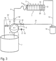
- the pigging station 1 has a compressed air module 19 with several compressed air connections 20 instead of the return module 8.
- Compressed air lines can be connected to the compressed air connections 20 in order to introduce compressed air into the central lines 3 of the pigging station 1.
- compressed air is introduced into the pressure line 4
- the coating agent in the pressure line 4 is then pressed back into the paint supply 7 via the circulation line 10 or 10' and thus recovered.
- a special feature of this embodiment is that a return line 21 also branches off from the coating agent pump 5 and opens into the dirt thinner receptacle 14. In the return line 21 there is a controllable return valve 22 which controls the fluid flow through the return line 21 into the dirt thinner receptacle 14.
- any residues of the coating agent or flushing agent remaining in the pressure line 4 can be blown out through the return line 21 into the dirt thinner holder 14.
- the return valve 22 is opened. Compressed air is then blown into the pressure line 4 at the compressed air module 19 of the pigging station 1, with the compressed air then blowing out the residues of coating agent and flushing agent from the pressure line 4 via the return line 21 into the dirt thinner holder 14.
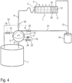
- a special feature of this embodiment is that an additional blow-out line 23 is provided, which opens into the inlet area of the coating agent pump 5, wherein a controllable blow-out valve 24 is arranged in the blow-out line 23.
- the blow-out line 23 can be used to blow out any coating agent remaining in the inlet area of the coating agent pump 5 from the coating agent pump 5, specifically through the suction line 6 back into the paint supply 7. In this way, the coating agent remaining in the inlet area of the coating agent pump 5 can be recovered in a flushing process. To do this, the blow-out valve 24 is simply opened, whereupon compressed air is blown into the inlet area of the coating agent pump 5. The blown-in compressed air then displaces the coating agent in the inlet area of the coating agent pump 5, which thus leaves the coating agent pump 5 via the pump inlet and the suction line 6 against the normal flow direction during coating operation and returns to the paint supply 7.
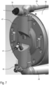
- the coating agent pump five initially has a pump inlet 25, which draws the coating agent to be pumped from the paint supply 7 via the suction line 6, wherein the coating agent flows in the direction of the arrow through the pump inlet 25 into the coating agent pump 5.
- the suctioned coating agent then passes from the pump inlet 25 into an inlet area 26 of the coating agent pump 5.
- the coating agent pump 5 On the outlet side, the coating agent pump 5 has a pump outlet 27 to which the pressure line 4 is connected, wherein the coating agent flows in the direction of the arrow through the pump outlet 27 out of the coating agent pump 5.
- the pump outlet 27 is fed with the coating agent to be pumped from an outlet area 28.
- an inlet valve 31 which controls the coating agent flow from the inlet region 26 into the pump chamber 29 so that the coating agent flows in the direction of the arrow from the inlet region 26 into the pump chamber 29.
- the inlet valve 31 is designed as a check valve and consists essentially of a valve ball 32, a valve seat 33 and a return spring 34, whereby the return spring 34 presses the valve ball 32 sealingly into the valve seat 33.
- the inlet valve 31 therefore only allows a coating agent flow from the inlet area 26 in the direction of the arrow into the pump chamber 29, whereas an oppositely directed coating agent flow is blocked by the inlet valve 31 against the direction of the arrow.
- An outlet valve 35 is arranged between the outlet region 28 and the pump chamber 29, which controls the flow of coating agent from the pump chamber 29 in the direction of the arrow into the outlet region 28.
- the outlet valve 35 is also designed as a check valve and consists of a return spring 36, a valve ball 37 and a valve seat 38, wherein the return spring 36 presses the valve ball 37 sealingly into the valve seat 38.
- the coating agent pump 5 has a circulation connection 39, wherein the circulation line 10 is connected to the circulation connection 39, which in the variant of the invention according to the Figures 2-4 shown with solid lines.
- a controllable circulation valve 40 is integrated into the circulation connection 39, which can optionally open or close the circulation connection 39.
- the coating agent pump 5 has two blow-out connections 41, 42, wherein the blow-out connection 41 serves to blow out the pump chamber 29, while the blow-out connection 42 serves to blow out the opposite pump chamber (not shown).
- the blow-out connection 41 opens into the inlet valve 31, specifically downstream behind the valve seat 33 with respect to the normal flow direction during coating operation. This means that when compressed air is supplied via the blow-out connection 41, the compressed air supports the force of the return spring 34 and additionally presses the valve ball 32 into the valve seat 33 to form a seal. The inlet valve 31 is then closed and the compressed air can penetrate into the pump chamber 29 through the blow-out connection 41 in order to blow it out.
- blow-out connection 42 functions in the same way with respect to the other pump chamber.
- the coating agent pump 5 has two blow-out connections 43, 44, which are connected to the inlet area 26 and enable coating agent located in the inlet area 26 to be blown out through the pump inlet 25 and returned to the paint supply 7.
- compressed air is supplied through the blow-out connections 43, 44 in the direction of the arrow.
- the coating agent located in the inlet area 26 is then blown in the opposite direction to the arrow in Figure 5 through the pump inlet 25 back to the ink supply 7.
- the coating agent pump 5 has a separate return connection 45, which is connected to the return line 21, which leads to the dirt thinner receptacle 14.
- the return connection 45 is connected to the outlet area 28 of the coating agent pump 5. Residues of coating agent and rinsing agent can be blown out of the pressure line 4 via the return connection 45. For this purpose, compressed air is blown into the pressure line 4 at the pigging station 1. As a result, the residues of the coating agent and rinsing agent in the pressure line 4 are pressed against the normal flow direction into the outlet area 28 of the coating agent pump 5 and then leave the coating agent pump 5 through the return connection 45 to the dirt thinner receptacle 14.
- the coating agent pump 5 has a substantially cylindrical pump housing 46 with two lateral housing covers 47, 48.
- the two exhaust connections 41, 43 and the circulation connection 39 with the circulation valve 40, the inlet valve 31 and the outlet valve 35 are integrated into the housing cover 47.
- the two housing covers 47, 48 are each made of stainless steel and are cast parts.
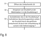
- a first step S1 the circulation valve 18 is first opened so that the coating agent remaining in the pressure line 4 can be led back into the paint supply 7 through the circulation line 10.
- step S2 compressed air is fed into the pressure line 4 at the pigging station 1.
- This compressed air pushes the coating agent in the pressure line 4 through the open circulation valve 18 and through the circulation line 10 back into the paint supply 7, so that this portion of the coating agent is recovered and does not produce any loss of coating agent.
- the return valve 22 in the return line 21 is first opened in a step S1.
- step S2 compressed air is then fed into the pressure line 4 again at the pigging station 1. This compressed air then presses the residues of the coating agent and the rinsing agent in the pressure line 4 first into the outlet area 28 of the coating agent pump 5 and from there via the open return valve 22 and the return line 21 into the dirt thinner holder 14.
- a first step S1 the circulation valve 18 is first opened.
- step S2 compressed air is then blown into the coating agent pump 5 again namely via the blow-out connections 41, 42.
- This compressed air penetrates into the pump chamber 29 or into the opposite second pump chamber and presses the coating agent located therein first into the outlet area 28 of the coating agent pump 5 and from there through the circulation connection 39 into the circulation line 10 and back into the paint supply 7. In this way, part of the coating agent remaining in the pump chamber 29 can be recovered.
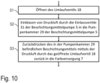
- a first step S1 compressed air is blown into the inlet area 26 of the coating agent pump 5 through the second blow-out connection 43 or 44.
- a second step S2 the injected compressed air then presses the residues of the coating agent remaining in the inlet area 26 through the pump inlet 25 and the suction line 6 back into the paint supply 7.
Landscapes
- Engineering & Computer Science (AREA)
- Mechanical Engineering (AREA)
- General Engineering & Computer Science (AREA)
- Coating Apparatus (AREA)
- Nozzles (AREA)
- Application Of Or Painting With Fluid Materials (AREA)
Claims (15)
- Pompe à produit de revêtement (5) pour le transport d'un produit de revêtement, aveca) une entrée de pompe (25) pour le logement du produit de revêtement à transporter,b) une zone d'entrée (26), qui est alimentée en produit de revêtement à partir de l'entrée de pompe (25),c) une sortie de pompe (27) pour la distribution du produit de revêtement à transporter etd) une zone de sortie (28) qui alimente la sortie de pompe (27) en produit de revêtement à transporter,
caractérisée pare) un raccord de circulation côté sortie (39) pour la distribution du produit de revêtement dans une conduite de circulation (10) qui retourne vers une alimentation de peinture (7), dans laquelle le raccord de circulation (39) de la pompe à produit de revêtement (5)e1) est prévu en plus de l'entrée de pompe (25) et de la sortie de pompe (27),e2) est relié avec la zone de sortie (28) de la pompe à produit de revêtement (5) ete3) est alimenté en produit de revêtement de retour à partir de la zone de sortie (28) de la pompe à produit de revêtement (5). - Pompe à produit de revêtement (5) selon la revendication 1, caractérisée par une vanne de circulation contrôlable (40) intégrée dans la pompe à produit de revêtement (5), pour le contrôle du flux de produit de revêtement sortant de la zone de sortie (28) de la pompe à produit de revêtement (5) à travers le raccord de circulation (39) vers la conduite de circulation (10).
- Pompe à produit de revêtement (5) selon la revendication 1 ou 2,
caractérisée para) un raccord de retour côté sortie (45) pour la distribution de résidus de produit de revêtement et/ou d'un produit de rinçage dans une conduite de retour (21) qui conduit à un logement de solvant d'impuretés (14), dans lequel le raccord de retour (45) de la pompe à produit de revêtement (5)a1) est prévu en plus de l'entrée de pompe (25), de la sortie de pompe (27) et du raccord de circulation (39),a2) est relié avec la zone de sortie (28) de la pompe à produit de revêtement (5) eta3) est alimenté en produit de revêtement de retour à partir de la zone de sortie (28) de la pompe à produit de revêtement (5) etb) une vanne de retour contrôlable (22) intégrée dans la pompe à produit de revêtement (5), pour le contrôle du flux de produit de revêtement sortant de la zone de sortie (28) de la pompe à produit de revêtement (5) à travers le raccord de retour (45) vers la conduite de retour (21) en direction du logement de solvant d'impuretés (14). - Pompe à produit de revêtement (5) selon l'une des revendications précédentes, caractérisée en ce que la pompe à produit de revêtement (5) est une pompe volumétrique (25) avec les caractéristiques suivantes :a) une chambre de pompe (29), dans laquelle la zone d'entrée (26) et la zone de sortie (28) sont reliées avec la chambre de pompe (29),b) un refouleur (30) disposé dans la chambre de pompe (29),c) un dispositif d'entraînement pour le déplacement du refouleur (30) pour le pompage du produit de revêtement,d) une vanne d'entrée (31) intégrée dans la pompe à produit de revêtement (5) entre la zone d'entrée (26) et la chambre de pompe (29) ete) une vanne de sortie (35) intégrée dans la pompe à produit de revêtement (5) entre la chambre de pompe (29) et la zone de sortie (28).
- Pompe à produit de revêtement (5) selon la revendication 4, caractérisée para) au moins un premier raccord de soufflage (41) pour le soufflage de la chambre de pompe (29) avec de l'air comprimé, dans laquelle le premier raccord de soufflage (41) débouche dans la chambre de pompe (29),b) au moins une première vanne de soufflage (41) intégrée dans la pompe à produit de revêtement (5), pour le contrôle du flux d'air comprimé à travers le premier raccord de soufflage (41) vers la chambre de pompe (29), qui libère un flux d'air comprimé à travers le premier raccord de soufflage (41) vers la chambre de pompe (29) et qui bloque un flux d'air comprimé hors de la chambre de pompe (29) à travers le premier raccord de soufflage (41),c) au moins un deuxième raccord de soufflage côté entrée (43, 44) pour le soufflage du produit de revêtement hors de la zone d'entrée (26) de la pompe à produit de revêtement (5) au moyen d'air comprimé, dans laquelle le deuxième raccord de soufflage (43, 44) débouche dans la zone d'entrée (26) de la pompe à produit de revêtement (5) etd) une deuxième vanne de soufflage contrôlable, intégrée dans la pompe à produit de revêtement (5), pour le contrôle du flux d'air comprimé à travers le deuxième raccord de soufflage (43, 44) vers la zone d'entrée (26) de la pompe à produit de revêtement (5).
- Pompe à produit de revêtement (5) selon l'une des revendications précédentes, caractérisée en ce quea) la pompe à produit de revêtement (5) est une pompe à double membrane aveca1) deux chambres de pompe (29),a2) deux vannes d'entrée (31) qui relient chacune une des deux chambres de pompe (29) avec la zone d'entrée (26) de la pompe à produit de revêtement (5),a3) deux vannes de sortie (35) qui relient chacune une des deux chambres de pompe (29) avec la zone de sortie (28) de la pompe à produit de revêtement (5),a4) deux membranes de pompe mobiles (30) qui sont disposées chacune dans une des deux chambres de pompe (29),a5) deux premiers raccords de soufflage (41, 42), chacune pour le soufflage d'une des deux chambres de pompe (29),a6) deux premières vannes de soufflage pour le contrôle du flux d'air comprimé à travers les premiers raccords de soufflage (41, 42) respectivement vers une des deux chambres de pompe (29),b) la pompe à double membrane comprend un carter de pompe (46) avec deux couvercles de carter opposés (47, 48),c) dans chacune des deux couvercles de carter (47, 48), sont intégrés les composants suivants :c1) une des deux vannes d'entrée (31),c2) une des deux vannes de sortie (35),c3) une des deux premières vannes de soufflage,c4) la vanne de circulation (40) ou la vanne de retour.
- Installation de revêtement pour le revêtement de composants, aveca) une alimentation en peinture (7) pour la mise à disposition du produit de revêtement à appliquer,b) une pompe à produit de revêtement (5) selon l'une des revendications précédentes, pour le transport du produit de revêtement hors de l'alimentation en peinture (7),c) une conduite sous pression (4), qui sort de la pompe à produit de revêtement (5) et qui est alimentée en produit de revêtement par la pompe à produit de revêtement (5),d) un point de prélèvement (1) qui est raccordé à la conduite sous pression (4) et qui est alimenté en produit de revêtement à partir de la conduite sous pression (4), dans laquelle le produit de revêtement, en mode revêtement, s'écoule dans une direction d'écoulement de la pompe à produit de revêtement (5) à travers la conduite sous pression (4) vers le point de prélèvement (1) ete) une conduite de circulation (10, 10') qui conduit à nouveau vers l'alimentation en peinture (7),f) dans laquelle la conduite de circulation (10, 10') bifurque en amont du point de prélèvement (1), par rapport à la direction d'écoulement en mode revêtement etg) dans laquelle la conduite de circulation (10, 10') bifurque à partir du raccord de circulation (39) de la pompe à produit de revêtement (5).
- Installation de revêtement selon la revendication 7, caractérisée par une vanne de circulation contrôlable (18, 18') pour le contrôle du flux de produit de revêtement dans la conduite de circulation (10, 10'), dans laquelle la vanne de circulation (18, 18') est intégrée dans la pompe à produit de revêtement (5).
- Installation de revêtement selon l'une des revendications 7 à 8, caractérisée para) un logement de solvant d'impuretés (14) pour le logement et l'élimination des résidus de produit de revêtement et d'un produit de rinçage après un processus de rinçage et/oub) une première conduite de retour (21) qui conduit vers le logement de solvant d'impuretés (14), dans laquelle la première conduite de retourb1) bifurque à partir d'un raccord de retour côté sortie (45) de la pompe à produit de revêtement (5),b2) bifurque entre la pompe à produit de revêtement (5) et le point de prélèvement (1) à partir de la conduite sous pression (4) etc) une deuxième conduite de retour (13), qui conduit du point de prélèvement (1) vers le logement de solvant d'impuretés (14),d) dans laquelle, pour le contrôle du flux de fluide à travers la première conduite de retour (21) vers le logement de solvant d'impuretés (14), une vanne de retour contrôlable (22) est prévue ete) la vanne de retour (22) est intégrée dans la pompe à produit de revêtement (5).
- Installation de revêtement selon l'une des revendications 7 à 9,
caractérisée en ce quea) la pompe à produit de revêtement (5) comprend au moins un premier raccord de soufflage (41, 42) pour le soufflage de la chambre de pompe (29) avec de l'air comprimé, dans laquelle le premier raccord de soufflage (41, 42) débouche dans la chambre de pompe (29),b) la pompe à produit de revêtement (5) comprend au moins une première vanne de soufflage (17) pour le contrôle du flux d'air comprimé à travers le premier raccord de soufflage (41, 42) vers la chambre de pompe (29), qui libère un flux d'air comprimé à travers le premier raccord de soufflage (41, 42) vers la chambre de pompe (29) et qui bloque un flux d'air comprimé sortant de la chambre de pompe (29) à travers le premier raccord de soufflage (41, 42),c) une première conduite de soufflage (16) est raccordée au premier raccord de soufflage (41, 42) de la pompe à produit de revêtement (5), afin de souffler de l'air comprimé. - Installation de revêtement selon l'une des revendications 7 à 10,
caractérisée en ce quea) la pompe à produit de revêtement (5) comprend au moins un deuxième raccord de soufflage côté entrée (43, 44) pour le soufflage du produit de revêtement hors de la zone d'entrée (26) de la pompe à produit de revêtement (5), dans laquelle le deuxième raccord de soufflage (43, 44) débouche dans la zone d'entrée (26) de la pompe à produit de revêtement (5),b) au moins une deuxième vanne de soufflage (24) est prévue pour le contrôle du flux d'air comprimé vers le deuxième raccord de soufflage (43, 44) de la pompe à produit de revêtement (5), qui libère un flux d'air comprimé à travers le deuxième raccord de soufflage (43, 44) vers la zone d'entrée (26) et qui bloque un flux d'air comprimé sortant de la zone d'entrée (26) à travers le deuxième raccord de soufflage (43, 44). - Installation de revêtement selon l'une des revendications 7 à 11, caractérisée en ce quea) la conduite de circulation (10, 10') présente une courte longueur de conduite de 2 m, 1 m, 50 cm ou 25 cm maximum etb) la pompe à produit de revêtement (5) est entraînée par de l'air comprimé avec une pression d'air d'entraînement et transporte le produit de revêtement avec une pression de refoulement, dans laquelle la pompe à produit de revêtement (5) présente un rapport de démultiplication entre la pression de refoulement et la pression d'air d'entraînement d'au moins 2:1 ou 4:1 et/ouc) la pompe à produit de revêtement (5) est une pompe à membrane etd) la pompe à produit de revêtement (5) comprend au moins un piston d'entraînement entraîné de manière pneumatique, au moins deux pistons d'entraînement et/oue) le point de prélèvement (1) alimente plusieurs conduites d'alimentation (2) qui conduisent chacune à un appareil d'application et qui alimentent l'appareil d'application respectif avec le produit de revêtement à appliquer etf) le point de prélèvement (1) comprend au moins un raccord d'air comprimé et au moins une vanne d'air comprimé contrôlable, afin de pouvoir introduire l'air comprimé au niveau du point de prélèvement (1) dans la conduite sous pression (4) etg) le point de prélèvement (1) comprend, pour le raccordement de la deuxième conduite de retour, un raccord de retour et, pour le contrôle du retour à travers la deuxième conduite de retour, une vanne de retour contrôlable eth) le point de prélèvement (1) comprend plusieurs canaux centraux (3) qui sont alimentés chacun en produit de revêtement par une conduite sous pression (4).
- Procédé de fonctionnement pour une installation de revêtement selon l'une des revendications 7 à 12, caractérisé par les étapes suivantes lors d'un processus de rinçage :a) ouverture de la vanne de circulation (18, 18'),b) introduction d'air comprimé au niveau du point de prélèvement (1) dans la conduite sous pression (4) etc) repoussage du produit de revêtement se trouvant dans la conduite sous pression (4) au moyen de l'air comprimé à travers la conduite de circulation (10, 10') vers l'alimentation en peinture (7).
- Procédé de fonctionnement selon la revendication 13, caractérisé par les étapes suivantes lors d'un processus de rinçage :a) ouverture de la vanne de retour (22) dans la première conduite de retour (21), introduction d'air comprimé au niveau du point de prélèvement (1) dans la conduite sous pression (4) et repoussage des quantités résiduelles de produit de rinçage et/ou de produit de revêtement hors de la conduite sous pression (4) et/ou hors de la zone de sortie (28) de la pompe à produit de revêtement (5) au moyen de l'air comprimé à travers la première conduite de retour vers le logement de solvant d'impuretés (14) et/oub) ouverture de la vanne de circulation (18, 18'), introduction d'air comprimé par la première conduite de soufflage (16) à travers la première vanne d'entrée (31), conçue comme un clapet anti-retour, vers la chambre de pompe (29) de la pompe à produit de revêtement (5) et repoussage du produit de revêtement se trouvant dans la pompe à produit de revêtement (5) au moyen de l'air comprimé de retour à travers la conduite de circulation (10, 10') à nouveau vers l'alimentation en peinture (7) et/ouc) soufflage d'air comprimé à travers la deuxième conduite de soufflage (23) dans le deuxième raccord de soufflage (43, 44) de la pompe à produit de revêtement (5) puis de là vers la zone d'entrée (26) de la pompe à produit de revêtement (5) et repoussage du produit de revêtement se trouvant dans la pompe à produit de revêtement (5) au moyen de l'air comprimé de retour à travers l'entrée de pompe (25) à nouveau vers l'alimentation en peinture (7).
- Procédé de fonctionnement selon l'une des revendications 13 à 14, caractérisé en ce quea) pendant le revêtement d'un composant, le produit de revêtement est pompé à travers la conduite sous pression (4) de la pompe à produit de revêtement (5) vers le point de prélèvement (1) etb) pendant un processus de rinçage, le produit de revêtement est conduit à travers la conduite sous pression (4) du point de prélèvement (1) à nouveau vers la pompe à produit de revêtement (5) et à travers la conduite de circulation (10, 10') à nouveau vers l'alimentation en peinture (7).
Applications Claiming Priority (2)
| Application Number | Priority Date | Filing Date | Title |
|---|---|---|---|
| DE102020109973.8A DE102020109973A1 (de) | 2020-04-09 | 2020-04-09 | Beschichtungsmittelpumpe, Beschichtungsanlage und zugehöriges Betriebsverfahren |
| PCT/EP2021/058845 WO2021204748A1 (fr) | 2020-04-09 | 2021-04-06 | Pompe pour agent de revêtement, installation de revêtement et procédé de fonctionnement associé |
Publications (2)
| Publication Number | Publication Date |
|---|---|
| EP4132722A1 EP4132722A1 (fr) | 2023-02-15 |
| EP4132722B1 true EP4132722B1 (fr) | 2024-11-20 |
Family
ID=75478016
Family Applications (1)
| Application Number | Title | Priority Date | Filing Date |
|---|---|---|---|
| EP21718058.7A Active EP4132722B1 (fr) | 2020-04-09 | 2021-04-06 | Pompe à agent de revêtement, installation de revêtement et procédé de fonctionnement associé |
Country Status (8)
| Country | Link |
|---|---|
| US (1) | US12583002B2 (fr) |
| EP (1) | EP4132722B1 (fr) |
| KR (1) | KR20220160011A (fr) |
| CN (1) | CN115348899A (fr) |
| DE (1) | DE102020109973A1 (fr) |
| MX (1) | MX2022012538A (fr) |
| WO (1) | WO2021204748A1 (fr) |
| ZA (1) | ZA202210212B (fr) |
Families Citing this family (4)
| Publication number | Priority date | Publication date | Assignee | Title |
|---|---|---|---|---|
| CN113351396A (zh) * | 2021-07-14 | 2021-09-07 | 东莞市金隆机械设备有限公司 | 一种喷涂供漆回收利用系统 |
| CN218167601U (zh) * | 2022-10-08 | 2022-12-30 | 宁德时代新能源科技股份有限公司 | 涂布模头和具有其的涂布设备 |
| DE102023102825A1 (de) * | 2023-02-06 | 2024-08-08 | Dürr Systems Ag | Beschichtungsmittel-Versorgungseinrichtung und zugehöriges Betriebsverfahren |
| CN116833008B (zh) * | 2023-06-30 | 2025-12-09 | 北京兴信易成机电工程有限公司 | 一种用于供漆的矩阵走珠式快速换色系统 |
Citations (2)
| Publication number | Priority date | Publication date | Assignee | Title |
|---|---|---|---|---|
| EP1284162B1 (fr) * | 2001-08-17 | 2005-10-26 | ITW Oberflächentechnik GmbH & Co.KG | Procédé et appareil pour nettoyer un système d'alimentation en peinture dans un appareil de revêtement |
| DE102006041677B4 (de) * | 2006-09-06 | 2019-05-29 | Eisenmann Se | System zur Reinigung von medienführenden Wegen in einer Beschichtungsanlage |
Family Cites Families (12)
| Publication number | Priority date | Publication date | Assignee | Title |
|---|---|---|---|---|
| DE3821440A1 (de) * | 1988-06-24 | 1989-12-28 | Behr Industrieanlagen | Verfahren und einrichtung zum zufuehren von spritzgut zu einer mehrzahl von spritzstaenden |
| DE4443778A1 (de) * | 1994-12-08 | 1996-06-20 | Abel Gmbh & Co | Doppelmembranpumpe |
| DE10225681B4 (de) | 2002-06-10 | 2010-02-04 | Windmöller & Hölscher Kg | Verfahren und Vorrichtung zum Zu- und Abführen von Druckfarbe zu und von einer Rakelvorrichtung eines Farbwerks einer Rotationsdruckmaschine und/oder zum Reinigen der Rakelvorrichtung |
| US7156112B2 (en) * | 2002-07-24 | 2007-01-02 | Filter And Coating Technology, Inc. | Method and apparatus for cleaning paint supply systems |
| ES2380260B2 (es) | 2010-05-18 | 2013-02-14 | Samoa Industrial S.A. | Bomba de doble membrana de flujo central |
| DE102012022836B3 (de) | 2012-11-23 | 2014-05-22 | Eisenmann Ag | Schlauchpumpe und Applikationssystem mit einer solchen |
| DE102013000362B4 (de) | 2013-01-10 | 2021-08-05 | Man Truck & Bus Se | Fahrerhauslagerung |
| DE102013003620B4 (de) * | 2013-02-18 | 2016-02-04 | Dürr Systems GmbH | Beschichtungsmittelpumpe und Reinigungsverfahren für eine Beschichtungsmittelpumpe |
| KR102180224B1 (ko) | 2013-07-19 | 2020-11-18 | 그라코 미네소타 인크. | 다중 지점 시일 윤활 시스템 |
| US10006456B2 (en) | 2014-08-01 | 2018-06-26 | Murzan, Inc. | Fully-draining diaphragm pump and check valve assembly |
| DE102017126651B4 (de) | 2017-11-13 | 2021-05-27 | Timmer Gmbh | Pumpeinrichtung mit über einem gemeinsamen Antrieb gekoppelten Pumpen |
| EP3725527B1 (fr) | 2019-04-19 | 2022-03-30 | Sheng-Tsung Lee | Système distributeur de fluide |
-
2020
- 2020-04-09 DE DE102020109973.8A patent/DE102020109973A1/de not_active Withdrawn
-
2021
- 2021-04-06 KR KR1020227035243A patent/KR20220160011A/ko not_active Ceased
- 2021-04-06 MX MX2022012538A patent/MX2022012538A/es unknown
- 2021-04-06 WO PCT/EP2021/058845 patent/WO2021204748A1/fr not_active Ceased
- 2021-04-06 EP EP21718058.7A patent/EP4132722B1/fr active Active
- 2021-04-06 US US17/916,888 patent/US12583002B2/en active Active
- 2021-04-06 CN CN202180024980.7A patent/CN115348899A/zh active Pending
-
2022
- 2022-09-14 ZA ZA2022/10212A patent/ZA202210212B/en unknown
Patent Citations (2)
| Publication number | Priority date | Publication date | Assignee | Title |
|---|---|---|---|---|
| EP1284162B1 (fr) * | 2001-08-17 | 2005-10-26 | ITW Oberflächentechnik GmbH & Co.KG | Procédé et appareil pour nettoyer un système d'alimentation en peinture dans un appareil de revêtement |
| DE102006041677B4 (de) * | 2006-09-06 | 2019-05-29 | Eisenmann Se | System zur Reinigung von medienführenden Wegen in einer Beschichtungsanlage |
Also Published As
| Publication number | Publication date |
|---|---|
| US12583002B2 (en) | 2026-03-24 |
| EP4132722A1 (fr) | 2023-02-15 |
| MX2022012538A (es) | 2022-12-13 |
| CN115348899A (zh) | 2022-11-15 |
| US20230158525A1 (en) | 2023-05-25 |
| KR20220160011A (ko) | 2022-12-05 |
| WO2021204748A1 (fr) | 2021-10-14 |
| ZA202210212B (en) | 2024-01-31 |
| DE102020109973A1 (de) | 2021-10-14 |
Similar Documents
| Publication | Publication Date | Title |
|---|---|---|
| EP4132722B1 (fr) | Pompe à agent de revêtement, installation de revêtement et procédé de fonctionnement associé | |
| DE19742588B4 (de) | Verfahren zum serienweisen Beschichten von Werkstücken | |
| EP0409001B1 (fr) | Dispositif d'injection de liquides | |
| EP2432695B1 (fr) | Station de remplissage mixte | |
| EP2129478B1 (fr) | Procédé de production d'un milieu nettoyant et procédé et dispositif de nettoyage pour nettoyer une pièce | |
| EP0865830B2 (fr) | Dispositif de changement de teinte avec sens de circulation de vernis réversible | |
| EP2128443A1 (fr) | Elément de pompe | |
| DE3127831A1 (de) | "system und vorrichtung zum pumpen" | |
| DE2010730A1 (de) | Einspritz-Öler für Druckluftleitungen | |
| DE2556169B2 (de) | Impulsgesteuerte Tropfenspritzeinrichtung | |
| EP2025978A2 (fr) | Distributeur pour un dispositif de nettoyage des vitres dans un véhicule | |
| EP2392408B1 (fr) | Dispositif d'application de colle et procédé de nettoyage de celui-ci | |
| AT517359B1 (de) | Vorrichtung mit intermittierend bereitgestellter flüssiger Kunststoffkomponente | |
| DE3029872A1 (de) | Verfahren und vorrichtung zum pumpen fliessfaehigen materials | |
| EP4281668B1 (fr) | Vanne pour produits épais et procédé d'actionnement d'une vanne pour produits épais | |
| DE2855916C2 (de) | Vorrichtung zum Herstellen eines Reaktionsgemisches aus Schaumstoff oder Massivstoff bildenden, fließfähigen Komponenten | |
| DE3026994C2 (de) | Vorrichtung zum Flüssigkeitswechsel, insbesondere bei Kraftfahrzeugen | |
| EP3899278B1 (fr) | Système de pompe | |
| DE19843695B4 (de) | Dosierpumpe | |
| EP1320415A1 (fr) | Dispositif pour l'application de liquides a pulveriser | |
| DE2416951A1 (de) | Hydraulischer verstaerker | |
| EP1384518B1 (fr) | Procédé ainsi qu'ensemble de valves pour commander le changement de couleur dans une installation de revêtement | |
| DE102006038389B4 (de) | Schmiermittel-Dosierpumpe und Dosierverfahren mit zwei gegeneinander beweglichen Kolben | |
| DE2716854A1 (de) | Kraftstoff-foerderanlage | |
| WO1995000251A1 (fr) | Dispositif de pulverisation sous haute pression |
Legal Events
| Date | Code | Title | Description |
|---|---|---|---|
| STAA | Information on the status of an ep patent application or granted ep patent |
Free format text: STATUS: UNKNOWN |
|
| STAA | Information on the status of an ep patent application or granted ep patent |
Free format text: STATUS: THE INTERNATIONAL PUBLICATION HAS BEEN MADE |
|
| PUAI | Public reference made under article 153(3) epc to a published international application that has entered the european phase |
Free format text: ORIGINAL CODE: 0009012 |
|
| STAA | Information on the status of an ep patent application or granted ep patent |
Free format text: STATUS: REQUEST FOR EXAMINATION WAS MADE |
|
| 17P | Request for examination filed |
Effective date: 20220722 |
|
| AK | Designated contracting states |
Kind code of ref document: A1 Designated state(s): AL AT BE BG CH CY CZ DE DK EE ES FI FR GB GR HR HU IE IS IT LI LT LU LV MC MK MT NL NO PL PT RO RS SE SI SK SM TR |
|
| P01 | Opt-out of the competence of the unified patent court (upc) registered |
Effective date: 20230512 |
|
| DAV | Request for validation of the european patent (deleted) | ||
| DAX | Request for extension of the european patent (deleted) | ||
| RIC1 | Information provided on ipc code assigned before grant |
Ipc: F04B 43/02 20060101ALI20240618BHEP Ipc: F04B 43/04 20060101ALI20240618BHEP Ipc: F04B 49/035 20060101ALI20240618BHEP Ipc: F04B 43/06 20060101ALI20240618BHEP Ipc: F04B 23/02 20060101ALI20240618BHEP Ipc: B05B 15/55 20180101ALI20240618BHEP Ipc: B05B 15/58 20180101ALI20240618BHEP Ipc: B05B 12/14 20060101ALI20240618BHEP Ipc: B05B 9/04 20060101AFI20240618BHEP |
|
| GRAP | Despatch of communication of intention to grant a patent |
Free format text: ORIGINAL CODE: EPIDOSNIGR1 |
|
| STAA | Information on the status of an ep patent application or granted ep patent |
Free format text: STATUS: GRANT OF PATENT IS INTENDED |
|
| INTG | Intention to grant announced |
Effective date: 20240726 |
|
| GRAS | Grant fee paid |
Free format text: ORIGINAL CODE: EPIDOSNIGR3 |
|
| GRAA | (expected) grant |
Free format text: ORIGINAL CODE: 0009210 |
|
| STAA | Information on the status of an ep patent application or granted ep patent |
Free format text: STATUS: THE PATENT HAS BEEN GRANTED |
|
| REG | Reference to a national code |
Ref country code: DE Ref legal event code: R081 Ref document number: 502021005869 Country of ref document: DE Owner name: DUERR SYSTEMS AG, DE Free format text: FORMER OWNER: ANMELDERANGABEN UNKLAR / UNVOLLSTAENDIG, 80297 MUENCHEN, DE |
|
| AK | Designated contracting states |
Kind code of ref document: B1 Designated state(s): AL AT BE BG CH CY CZ DE DK EE ES FI FR GB GR HR HU IE IS IT LI LT LU LV MC MK MT NL NO PL PT RO RS SE SI SK SM TR |
|
| REG | Reference to a national code |
Ref country code: GB Ref legal event code: FG4D Free format text: NOT ENGLISH |
|
| REG | Reference to a national code |
Ref country code: CH Ref legal event code: EP |
|
| REG | Reference to a national code |
Ref country code: DE Ref legal event code: R096 Ref document number: 502021005869 Country of ref document: DE |
|
| REG | Reference to a national code |
Ref country code: IE Ref legal event code: FG4D Free format text: LANGUAGE OF EP DOCUMENT: GERMAN |
|
| REG | Reference to a national code |
Ref country code: LT Ref legal event code: MG9D |
|
| REG | Reference to a national code |
Ref country code: NL Ref legal event code: MP Effective date: 20241120 |
|
| PG25 | Lapsed in a contracting state [announced via postgrant information from national office to epo] |
Ref country code: PT Free format text: LAPSE BECAUSE OF FAILURE TO SUBMIT A TRANSLATION OF THE DESCRIPTION OR TO PAY THE FEE WITHIN THE PRESCRIBED TIME-LIMIT Effective date: 20250320 Ref country code: IS Free format text: LAPSE BECAUSE OF FAILURE TO SUBMIT A TRANSLATION OF THE DESCRIPTION OR TO PAY THE FEE WITHIN THE PRESCRIBED TIME-LIMIT Effective date: 20250320 Ref country code: HR Free format text: LAPSE BECAUSE OF FAILURE TO SUBMIT A TRANSLATION OF THE DESCRIPTION OR TO PAY THE FEE WITHIN THE PRESCRIBED TIME-LIMIT Effective date: 20241120 |
|
| PG25 | Lapsed in a contracting state [announced via postgrant information from national office to epo] |
Ref country code: FI Free format text: LAPSE BECAUSE OF FAILURE TO SUBMIT A TRANSLATION OF THE DESCRIPTION OR TO PAY THE FEE WITHIN THE PRESCRIBED TIME-LIMIT Effective date: 20241120 Ref country code: NL Free format text: LAPSE BECAUSE OF FAILURE TO SUBMIT A TRANSLATION OF THE DESCRIPTION OR TO PAY THE FEE WITHIN THE PRESCRIBED TIME-LIMIT Effective date: 20241120 |
|
| PG25 | Lapsed in a contracting state [announced via postgrant information from national office to epo] |
Ref country code: BG Free format text: LAPSE BECAUSE OF FAILURE TO SUBMIT A TRANSLATION OF THE DESCRIPTION OR TO PAY THE FEE WITHIN THE PRESCRIBED TIME-LIMIT Effective date: 20241120 |
|
| PG25 | Lapsed in a contracting state [announced via postgrant information from national office to epo] |
Ref country code: ES Free format text: LAPSE BECAUSE OF FAILURE TO SUBMIT A TRANSLATION OF THE DESCRIPTION OR TO PAY THE FEE WITHIN THE PRESCRIBED TIME-LIMIT Effective date: 20241120 |
|
| PG25 | Lapsed in a contracting state [announced via postgrant information from national office to epo] |
Ref country code: NO Free format text: LAPSE BECAUSE OF FAILURE TO SUBMIT A TRANSLATION OF THE DESCRIPTION OR TO PAY THE FEE WITHIN THE PRESCRIBED TIME-LIMIT Effective date: 20250220 |
|
| PG25 | Lapsed in a contracting state [announced via postgrant information from national office to epo] |
Ref country code: GR Free format text: LAPSE BECAUSE OF FAILURE TO SUBMIT A TRANSLATION OF THE DESCRIPTION OR TO PAY THE FEE WITHIN THE PRESCRIBED TIME-LIMIT Effective date: 20250221 Ref country code: LV Free format text: LAPSE BECAUSE OF FAILURE TO SUBMIT A TRANSLATION OF THE DESCRIPTION OR TO PAY THE FEE WITHIN THE PRESCRIBED TIME-LIMIT Effective date: 20241120 |
|
| PG25 | Lapsed in a contracting state [announced via postgrant information from national office to epo] |
Ref country code: PL Free format text: LAPSE BECAUSE OF FAILURE TO SUBMIT A TRANSLATION OF THE DESCRIPTION OR TO PAY THE FEE WITHIN THE PRESCRIBED TIME-LIMIT Effective date: 20241120 |
|
| PG25 | Lapsed in a contracting state [announced via postgrant information from national office to epo] |
Ref country code: RS Free format text: LAPSE BECAUSE OF FAILURE TO SUBMIT A TRANSLATION OF THE DESCRIPTION OR TO PAY THE FEE WITHIN THE PRESCRIBED TIME-LIMIT Effective date: 20250220 |
|
| PG25 | Lapsed in a contracting state [announced via postgrant information from national office to epo] |
Ref country code: SM Free format text: LAPSE BECAUSE OF FAILURE TO SUBMIT A TRANSLATION OF THE DESCRIPTION OR TO PAY THE FEE WITHIN THE PRESCRIBED TIME-LIMIT Effective date: 20241120 |
|
| PGFP | Annual fee paid to national office [announced via postgrant information from national office to epo] |
Ref country code: DE Payment date: 20250422 Year of fee payment: 5 |
|
| PG25 | Lapsed in a contracting state [announced via postgrant information from national office to epo] |
Ref country code: DK Free format text: LAPSE BECAUSE OF FAILURE TO SUBMIT A TRANSLATION OF THE DESCRIPTION OR TO PAY THE FEE WITHIN THE PRESCRIBED TIME-LIMIT Effective date: 20241120 |
|
| PG25 | Lapsed in a contracting state [announced via postgrant information from national office to epo] |
Ref country code: EE Free format text: LAPSE BECAUSE OF FAILURE TO SUBMIT A TRANSLATION OF THE DESCRIPTION OR TO PAY THE FEE WITHIN THE PRESCRIBED TIME-LIMIT Effective date: 20241120 |
|
| PG25 | Lapsed in a contracting state [announced via postgrant information from national office to epo] |
Ref country code: RO Free format text: LAPSE BECAUSE OF FAILURE TO SUBMIT A TRANSLATION OF THE DESCRIPTION OR TO PAY THE FEE WITHIN THE PRESCRIBED TIME-LIMIT Effective date: 20241120 |
|
| PGFP | Annual fee paid to national office [announced via postgrant information from national office to epo] |
Ref country code: AT Payment date: 20250721 Year of fee payment: 5 |
|
| PG25 | Lapsed in a contracting state [announced via postgrant information from national office to epo] |
Ref country code: SK Free format text: LAPSE BECAUSE OF FAILURE TO SUBMIT A TRANSLATION OF THE DESCRIPTION OR TO PAY THE FEE WITHIN THE PRESCRIBED TIME-LIMIT Effective date: 20241120 |
|
| PG25 | Lapsed in a contracting state [announced via postgrant information from national office to epo] |
Ref country code: CZ Free format text: LAPSE BECAUSE OF FAILURE TO SUBMIT A TRANSLATION OF THE DESCRIPTION OR TO PAY THE FEE WITHIN THE PRESCRIBED TIME-LIMIT Effective date: 20241120 |
|
| PG25 | Lapsed in a contracting state [announced via postgrant information from national office to epo] |
Ref country code: IT Free format text: LAPSE BECAUSE OF FAILURE TO SUBMIT A TRANSLATION OF THE DESCRIPTION OR TO PAY THE FEE WITHIN THE PRESCRIBED TIME-LIMIT Effective date: 20241120 |
|
| REG | Reference to a national code |
Ref country code: DE Ref legal event code: R097 Ref document number: 502021005869 Country of ref document: DE |
|
| PG25 | Lapsed in a contracting state [announced via postgrant information from national office to epo] |
Ref country code: SE Free format text: LAPSE BECAUSE OF FAILURE TO SUBMIT A TRANSLATION OF THE DESCRIPTION OR TO PAY THE FEE WITHIN THE PRESCRIBED TIME-LIMIT Effective date: 20241120 |
|
| PLBE | No opposition filed within time limit |
Free format text: ORIGINAL CODE: 0009261 |
|
| STAA | Information on the status of an ep patent application or granted ep patent |
Free format text: STATUS: NO OPPOSITION FILED WITHIN TIME LIMIT |
|
| 26N | No opposition filed |
Effective date: 20250821 |
|
| REG | Reference to a national code |
Ref country code: CH Ref legal event code: H13 Free format text: ST27 STATUS EVENT CODE: U-0-0-H10-H13 (AS PROVIDED BY THE NATIONAL OFFICE) Effective date: 20251125 |
|
| PG25 | Lapsed in a contracting state [announced via postgrant information from national office to epo] |
Ref country code: LU Free format text: LAPSE BECAUSE OF NON-PAYMENT OF DUE FEES Effective date: 20250406 |
|
| PG25 | Lapsed in a contracting state [announced via postgrant information from national office to epo] |
Ref country code: MC Free format text: LAPSE BECAUSE OF FAILURE TO SUBMIT A TRANSLATION OF THE DESCRIPTION OR TO PAY THE FEE WITHIN THE PRESCRIBED TIME-LIMIT Effective date: 20241120 |
|
| GBPC | Gb: european patent ceased through non-payment of renewal fee |
Effective date: 20250406 |
|
| REG | Reference to a national code |
Ref country code: BE Ref legal event code: MM Effective date: 20250430 |
|
| PG25 | Lapsed in a contracting state [announced via postgrant information from national office to epo] |
Ref country code: GB Free format text: LAPSE BECAUSE OF NON-PAYMENT OF DUE FEES Effective date: 20250406 |
|
| PG25 | Lapsed in a contracting state [announced via postgrant information from national office to epo] |
Ref country code: FR Free format text: LAPSE BECAUSE OF NON-PAYMENT OF DUE FEES Effective date: 20250430 |
|
| PG25 | Lapsed in a contracting state [announced via postgrant information from national office to epo] |
Ref country code: BE Free format text: LAPSE BECAUSE OF NON-PAYMENT OF DUE FEES Effective date: 20250430 |
|
| PG25 | Lapsed in a contracting state [announced via postgrant information from national office to epo] |
Ref country code: CH Free format text: LAPSE BECAUSE OF NON-PAYMENT OF DUE FEES Effective date: 20250430 |
|
| PG25 | Lapsed in a contracting state [announced via postgrant information from national office to epo] |
Ref country code: IE Free format text: LAPSE BECAUSE OF NON-PAYMENT OF DUE FEES Effective date: 20250406 |