EP3242032A1 - Pompe à entrefer dans laquelle aussi bien le stator du moteur que l'unité électronique sont enrobés - Google Patents
Pompe à entrefer dans laquelle aussi bien le stator du moteur que l'unité électronique sont enrobés Download PDFInfo
- Publication number
- EP3242032A1 EP3242032A1 EP16168323.0A EP16168323A EP3242032A1 EP 3242032 A1 EP3242032 A1 EP 3242032A1 EP 16168323 A EP16168323 A EP 16168323A EP 3242032 A1 EP3242032 A1 EP 3242032A1
- Authority
- EP
- European Patent Office
- Prior art keywords
- housing
- motor housing
- motor
- potting compound
- axial end
- Prior art date
- Legal status (The legal status is an assumption and is not a legal conclusion. Google has not performed a legal analysis and makes no representation as to the accuracy of the status listed.)
- Granted
Links
Images
Classifications
-
- H—ELECTRICITY
- H02—GENERATION; CONVERSION OR DISTRIBUTION OF ELECTRIC POWER
- H02K—DYNAMO-ELECTRIC MACHINES
- H02K5/00—Casings; Enclosures; Supports
- H02K5/04—Casings or enclosures characterised by the shape, form or construction thereof
- H02K5/12—Casings or enclosures characterised by the shape, form or construction thereof specially adapted for operating in liquid or gas
- H02K5/132—Submersible electric motors
-
- H—ELECTRICITY
- H02—GENERATION; CONVERSION OR DISTRIBUTION OF ELECTRIC POWER
- H02K—DYNAMO-ELECTRIC MACHINES
- H02K5/00—Casings; Enclosures; Supports
- H02K5/04—Casings or enclosures characterised by the shape, form or construction thereof
- H02K5/22—Auxiliary parts of casings not covered by groups H02K5/06-H02K5/20, e.g. shaped to form connection boxes or terminal boxes
- H02K5/225—Terminal boxes or connection arrangements
-
- F—MECHANICAL ENGINEERING; LIGHTING; HEATING; WEAPONS; BLASTING
- F04—POSITIVE - DISPLACEMENT MACHINES FOR LIQUIDS; PUMPS FOR LIQUIDS OR ELASTIC FLUIDS
- F04D—NON-POSITIVE-DISPLACEMENT PUMPS
- F04D13/00—Pumping installations or systems
- F04D13/02—Units comprising pumps and their driving means
- F04D13/06—Units comprising pumps and their driving means the pump being electrically driven
-
- F—MECHANICAL ENGINEERING; LIGHTING; HEATING; WEAPONS; BLASTING
- F04—POSITIVE - DISPLACEMENT MACHINES FOR LIQUIDS; PUMPS FOR LIQUIDS OR ELASTIC FLUIDS
- F04D—NON-POSITIVE-DISPLACEMENT PUMPS
- F04D13/00—Pumping installations or systems
- F04D13/02—Units comprising pumps and their driving means
- F04D13/06—Units comprising pumps and their driving means the pump being electrically driven
- F04D13/0606—Canned motor pumps
- F04D13/064—Details of the magnetic circuit
-
- F—MECHANICAL ENGINEERING; LIGHTING; HEATING; WEAPONS; BLASTING
- F04—POSITIVE - DISPLACEMENT MACHINES FOR LIQUIDS; PUMPS FOR LIQUIDS OR ELASTIC FLUIDS
- F04D—NON-POSITIVE-DISPLACEMENT PUMPS
- F04D13/00—Pumping installations or systems
- F04D13/02—Units comprising pumps and their driving means
- F04D13/06—Units comprising pumps and their driving means the pump being electrically driven
- F04D13/0686—Mechanical details of the pump control unit
-
- F—MECHANICAL ENGINEERING; LIGHTING; HEATING; WEAPONS; BLASTING
- F04—POSITIVE - DISPLACEMENT MACHINES FOR LIQUIDS; PUMPS FOR LIQUIDS OR ELASTIC FLUIDS
- F04D—NON-POSITIVE-DISPLACEMENT PUMPS
- F04D13/00—Pumping installations or systems
- F04D13/02—Units comprising pumps and their driving means
- F04D13/06—Units comprising pumps and their driving means the pump being electrically driven
- F04D13/0693—Details or arrangements of the wiring
-
- F—MECHANICAL ENGINEERING; LIGHTING; HEATING; WEAPONS; BLASTING
- F04—POSITIVE - DISPLACEMENT MACHINES FOR LIQUIDS; PUMPS FOR LIQUIDS OR ELASTIC FLUIDS
- F04D—NON-POSITIVE-DISPLACEMENT PUMPS
- F04D29/00—Details, component parts, or accessories
- F04D29/02—Selection of particular materials
- F04D29/026—Selection of particular materials especially adapted for liquid pumps
-
- F—MECHANICAL ENGINEERING; LIGHTING; HEATING; WEAPONS; BLASTING
- F04—POSITIVE - DISPLACEMENT MACHINES FOR LIQUIDS; PUMPS FOR LIQUIDS OR ELASTIC FLUIDS
- F04D—NON-POSITIVE-DISPLACEMENT PUMPS
- F04D29/00—Details, component parts, or accessories
- F04D29/40—Casings; Connections of working fluid
- F04D29/406—Casings; Connections of working fluid especially adapted for liquid pumps
-
- F—MECHANICAL ENGINEERING; LIGHTING; HEATING; WEAPONS; BLASTING
- F04—POSITIVE - DISPLACEMENT MACHINES FOR LIQUIDS; PUMPS FOR LIQUIDS OR ELASTIC FLUIDS
- F04D—NON-POSITIVE-DISPLACEMENT PUMPS
- F04D29/00—Details, component parts, or accessories
- F04D29/60—Mounting; Assembling; Disassembling
- F04D29/62—Mounting; Assembling; Disassembling of radial or helico-centrifugal pumps
- F04D29/628—Mounting; Assembling; Disassembling of radial or helico-centrifugal pumps especially adapted for liquid pumps
-
- H—ELECTRICITY
- H02—GENERATION; CONVERSION OR DISTRIBUTION OF ELECTRIC POWER
- H02K—DYNAMO-ELECTRIC MACHINES
- H02K11/00—Structural association of dynamo-electric machines with electric components or with devices for shielding, monitoring or protection
- H02K11/30—Structural association with control circuits or drive circuits
- H02K11/33—Drive circuits, e.g. power electronics
-
- H—ELECTRICITY
- H02—GENERATION; CONVERSION OR DISTRIBUTION OF ELECTRIC POWER
- H02K—DYNAMO-ELECTRIC MACHINES
- H02K15/00—Processes or apparatus specially adapted for manufacturing, assembling, maintaining or repairing of dynamo-electric machines
- H02K15/14—Casings; Enclosures; Supports
-
- H—ELECTRICITY
- H02—GENERATION; CONVERSION OR DISTRIBUTION OF ELECTRIC POWER
- H02K—DYNAMO-ELECTRIC MACHINES
- H02K5/00—Casings; Enclosures; Supports
- H02K5/04—Casings or enclosures characterised by the shape, form or construction thereof
-
- H—ELECTRICITY
- H02—GENERATION; CONVERSION OR DISTRIBUTION OF ELECTRIC POWER
- H02K—DYNAMO-ELECTRIC MACHINES
- H02K5/00—Casings; Enclosures; Supports
- H02K5/04—Casings or enclosures characterised by the shape, form or construction thereof
- H02K5/10—Casings or enclosures characterised by the shape, form or construction thereof with arrangements for protection from ingress, e.g. water or fingers
-
- H—ELECTRICITY
- H02—GENERATION; CONVERSION OR DISTRIBUTION OF ELECTRIC POWER
- H02K—DYNAMO-ELECTRIC MACHINES
- H02K5/00—Casings; Enclosures; Supports
- H02K5/04—Casings or enclosures characterised by the shape, form or construction thereof
- H02K5/12—Casings or enclosures characterised by the shape, form or construction thereof specially adapted for operating in liquid or gas
- H02K5/128—Casings or enclosures characterised by the shape, form or construction thereof specially adapted for operating in liquid or gas using air-gap sleeves or air-gap discs
- H02K5/1282—Casings or enclosures characterised by the shape, form or construction thereof specially adapted for operating in liquid or gas using air-gap sleeves or air-gap discs the partition wall in the air-gap being non cylindrical
-
- F—MECHANICAL ENGINEERING; LIGHTING; HEATING; WEAPONS; BLASTING
- F04—POSITIVE - DISPLACEMENT MACHINES FOR LIQUIDS; PUMPS FOR LIQUIDS OR ELASTIC FLUIDS
- F04D—NON-POSITIVE-DISPLACEMENT PUMPS
- F04D29/00—Details, component parts, or accessories
- F04D29/18—Rotors
-
- F—MECHANICAL ENGINEERING; LIGHTING; HEATING; WEAPONS; BLASTING
- F05—INDEXING SCHEMES RELATING TO ENGINES OR PUMPS IN VARIOUS SUBCLASSES OF CLASSES F01-F04
- F05D—INDEXING SCHEME FOR ASPECTS RELATING TO NON-POSITIVE-DISPLACEMENT MACHINES OR ENGINES, GAS-TURBINES OR JET-PROPULSION PLANTS
- F05D2230/00—Manufacture
- F05D2230/20—Manufacture essentially without removing material
- F05D2230/21—Manufacture essentially without removing material by casting
-
- F—MECHANICAL ENGINEERING; LIGHTING; HEATING; WEAPONS; BLASTING
- F05—INDEXING SCHEMES RELATING TO ENGINES OR PUMPS IN VARIOUS SUBCLASSES OF CLASSES F01-F04
- F05D—INDEXING SCHEME FOR ASPECTS RELATING TO NON-POSITIVE-DISPLACEMENT MACHINES OR ENGINES, GAS-TURBINES OR JET-PROPULSION PLANTS
- F05D2230/00—Manufacture
- F05D2230/20—Manufacture essentially without removing material
- F05D2230/23—Manufacture essentially without removing material by permanently joining parts together
-
- F—MECHANICAL ENGINEERING; LIGHTING; HEATING; WEAPONS; BLASTING
- F05—INDEXING SCHEMES RELATING TO ENGINES OR PUMPS IN VARIOUS SUBCLASSES OF CLASSES F01-F04
- F05D—INDEXING SCHEME FOR ASPECTS RELATING TO NON-POSITIVE-DISPLACEMENT MACHINES OR ENGINES, GAS-TURBINES OR JET-PROPULSION PLANTS
- F05D2300/00—Materials; Properties thereof
- F05D2300/40—Organic materials
- F05D2300/43—Synthetic polymers, e.g. plastics; Rubber
-
- H—ELECTRICITY
- H02—GENERATION; CONVERSION OR DISTRIBUTION OF ELECTRIC POWER
- H02K—DYNAMO-ELECTRIC MACHINES
- H02K7/00—Arrangements for handling mechanical energy structurally associated with dynamo-electric machines, e.g. structural association with mechanical driving motors or auxiliary dynamo-electric machines
- H02K7/14—Structural association with mechanical loads, e.g. with hand-held machine tools or fans
Definitions
- the invention relates to a circulating pump unit according to the preamble of claim 1 and a method for manufacturing a circulating pump unit.
- Umisselzpumpenaggregate especially for heating systems or for Brauchiganum remplilzung known, which have a pump housing with a rotating impeller and a directly connected to the pump housing drive motor.
- motor electronics for controlling the drive motor are still present, which in particular may have a frequency converter.
- the drive motors are usually designed as wet-running motors, that is, they have a disposed between the rotor and the stator of the drive motor split tube, so that the rotor rotates in the medium to be conveyed.
- a special embodiment of these circulating pumps are circulating pumps with a so-called spherical motor, in which a structural unit of impeller and rotor is rotatably mounted on a central bearing ball.
- the split tube is designed as a dome-shaped containment shell, which extends concentrically around the bearing ball.
- the circulating pump unit has a wet-running electric drive motor, that is to say a drive motor, in which the rotor, which rotatably drives the impeller, rotates in the liquid to be conveyed.
- the rotor is separated from a stator of the drive motor by a split pot, so that the stator does not come into contact with the liquid to be conveyed.
- Rotationally connected to the rotor is in a known manner a centrifugal impeller, which promotes liquid inside a pump housing.
- the pump housing has a fluid inlet and outlet, as well as the necessary ducting to the impeller and away from the impeller.
- a motor housing Connected to the pump housing is a motor housing, which forms a combined stator and electronics housing in the circulation pump assembly according to the invention, in which both the stator of the drive motor and a required engine electronics are arranged.
- the engine electronics may in particular have a frequency converter for controlling the drive motor in order to enable a speed control of the drive motor.
- the motor housing is formed so that it is closed at a first axial end by a split pot of the drive motor.
- This first axial end is in the direction of the longitudinal axis, which corresponds to the axis of rotation of the drive motor, seen that axial end, which faces the pump housing and adjacent to the pump housing.
- the axial direction so it is always meant the longitudinal direction in the direction of the axis of rotation of the drive motor.
- the term gap filter is to be understood as meaning any shaped separating elements which separate the fluid chamber filled with liquid from the dry stator space.
- the containment shell may also be a split tube, which is suitably closed at its end extending into the interior of the motor housing.
- the containment shell can also be designed, for example, as a flat plate or disk, if the rotor and stator do not engage in one another, but lie opposite each other axially.
- Essential to the invention is only that the containment shell or the separating element between the rotor and stator, the motor housing closes at its end facing the pump housing to allow filling of the motor housing with the potting compound.
- the motor housing has an outer circumferential wall, which may be substantially tubular overall and is closed in the manner described at the first axial end through the containment shell.
- the containment shell and the peripheral wall together form a pot-shaped or cup-shaped form, wherein the containment shell can extend from the first axial end into the interior of the motor housing.
- the containment shell defines together with a peripheral wall of the motor housing an interior space which is closed to the first axial end through the containment shell.
- the motor housing has an opening which is closed by a lid.
- the cover is a separate component which is at least largely formed separately from the peripheral wall of the motor housing and is subsequently attached to the peripheral wall in order to close the opening at the second axial end.
- the potting compound surrounds or surrounds both the stator and the engine electronics in the interior of the motor housing.
- the potting compound thus represents an encapsulation of the electrical or electronic components in the interior of the motor housing, which seals the electrical or electronic components in particular to the outside and protects against moisture. In this way, further seals on the motor housing, for example between the cover and a peripheral wall of the motor housing or between the containment shell and the motor housing superfluous. It can thus be achieved in a very simple manner ensuring the electrical safety sealing all electrical components inside the motor housing.
- the potting compound is an additional fixation of the stator and the engine electronics in the interior of the motor housing, so that vibrations of the arranged in the motor housing components are avoided. The components are securely fixed by the surrounding potting compound.
- the cover is connected to the motor housing preferably non-positively, positively and / or cohesively.
- this is a compound which can be subsequently produced after assembly of the stator and the engine electronics in the interior of the motor housing.
- latching or snap connections can be provided, which engage the lid on the motor housing enable.
- a clamping connection and / or a material connection, such as welding or gluing are possible.
- the connection between the cover and the motor housing or a peripheral wall of the motor housing is designed so that it is no longer destructive to solve after the connection between the cover and the motor housing.
- a permanent closure of the motor housing can be realized by the lid.
- display and / or operating elements can be arranged on or in the lid.
- the display elements may be, for example, light-emitting diodes, a display or the like.
- controls such as switches or buttons, can be arranged on or in the lid. These can be, for example, sensor buttons or pushbuttons.
- An electrical connection to the further engine electronics arranged in the motor housing can be realized by plug contacts or at least a cable connection between the cover and the engine electronics. For this purpose, it is possible that corresponding connection contacts or at least one connection cable extend out of the potting compound towards the cover.
- the area filled with the potting compound is spaced from the second axial end of the motor housing and / or an inner side of the lid.
- the second axial end facing surface of the potting compound from the second axial end of the motor housing and the second axial end of the peripheral wall of the motor housing and / or the inside of the lid is spaced.
- stator and the engine electronics are spaced from the second axial end and in particular the opening at the second axial end by a dimension which is greater than the required cladding thickness with which the potting compound must encase the electrical or electronic components. That is, the dimension is chosen so large that certain variations in the filling quantity of the potting compound are tolerable.
- the circulating pump unit has at least one electrical connecting cable.
- an electrical connection cable can in particular serve the power supply of the drive motor.
- the connection cable or an additional connecting cable can also be used for data communication, for example to connect the circulating pump unit to an external controller or, if necessary, to external sensors.
- the at least one electrical connection cable is arranged so that it extends outwardly from the motor housing.
- the motor housing preferably has an opening through which the connecting cable extends to the outside. Particularly preferably, this opening is formed in the interface or in the contact region between the cover and the motor housing or between the cover and peripheral wall of the motor housing.
- connection cable with the cover removed can be easily inserted and then the lid can be placed, leaving the required for the connection cable opening between the lid and the motor housing.
- connection cable does not have to be threaded through an opening in the interior of the motor housing. Due to the potting compound inside the motor housing, preferably no seal in the region of the opening is required.
- the at least one electrical connection cable extends with one end into the potting compound in such a way that this end is embedded in the potting compound in such a way that the potting compound engages with a sheathing of the connection cable as a strain relief. That is, the potting compound forms the strain relief and there are preferably no further clamping means for a strain relief required, whereby the assembly is further simplified.
- the connecting cable extends out of the potting compound in a direction facing the second axial end and laterally extends outward from the motor housing transversely to this direction.
- Such a configuration has the advantage that in the area which is filled with the potting compound, no radially outwardly directed opening in the motor housing or its peripheral wall must be formed, through which these could flow during filling of the potting compound to the outside.
- the connection cable preferably extends outwards from a surface of the potting compound which is located at the top during casting.
- the motor housing is formed from at least two housing parts, wherein a first housing part is connected to the pump housing and a second housing part with the first housing part force, form and / or cohesively connected, wherein the first and the second housing part together define the interior with the area filled with potting compound.
- the first housing part is preferably connected to the gap pot at the first axial end.
- the second housing part is further preferably tubular and connected to the first axial end facing away from the open end of the first housing part with this.
- the first and the second housing part can be inserted into one another in this area, so that their circumferential walls overlap one another.
- the second housing part overlaps the first housing part on its outer circumference. That is, the first housing part has at its axial end facing the pump housing an inner cross section, which corresponds to the outer cross section of the first housing part at its axial end remote from the pump housing.
- the two-part design of the motor housing has the advantage that in the first housing part of the stator and the containment shell, that is, the essential components of the drive motor can be fixed.
- This first housing part may be formed as a standard part, while the second housing part is then easily adapted to various customer requirements.
- the second housing part can be easily varied in design and, moreover, in particular also be adapted in size and / or shape to the male electronics.
- different electronic components may be arranged in the second housing part and / or operating elements may be formed or arranged on the second housing part and / or the cover.
- the first and the second housing part are formed adjacent to the interior so that the potting compound causes a positive connection between the first and the second housing part.
- the first and / or the second housing part may have projections or shoulders facing the interior, which are enclosed by the potting compound in such a way that undercuts encompassed by the potting compound are formed in the axial direction.
- the potting compound can prevent the first and second housing parts in the axial direction in which they previously joined together have been pulled apart again.
- Such a positive connection may be present in addition to a non-positive connection between the two housing parts.
- the first housing part is fixed by means of a union nut on the pump housing, wherein the union nut engages over a projection on the first housing part and is releasably engaged with a thread on the pump housing.
- the union nut can rotate relative to the first housing part to be screwed onto the thread of the pump housing and unscrewed from this again.
- Such a union nut allows an easy-to-release connection between the motor housing and the pump housing, so that the motor housing for maintenance and repair purposes can be easily removed from the pump housing.
- the cap nut preferably has a radially inwardly directed collar, which has an inner diameter which is smaller than the outer diameter of the radially outwardly directed projection on the first housing part.
- the nut comes in the axial direction of the projection to the plant and can exert on the projection of an axial force to press the first housing part of the motor housing and thus the entire motor housing against the pump housing.
- the axis of rotation of the union nut preferably corresponds to the axis of rotation of the drive motor or extends parallel to this.
- the second housing part is arranged on the first housing part so that the second housing part secures the union nut in the axial direction of the first housing part. This is done, for example, in such a way that the second housing part engages over the first housing part on its outer circumference, so that the end edge of the second housing part, which faces the pump housing, faces an axial end side of the cap nut in such a way, that the union nut, when it moves in the axial direction to the second housing part, comes to this end edge to the plant.
- the assembly takes place in such a way that the union nut is placed on the first housing part, before the second housing part is connected to the first housing part. In this way, the union nut is captively secured to the motor housing.
- the containment shell is formed integrally with the motor housing, in particular made of plastic. If the motor housing is formed from two housing parts, the containment shell is thus preferably made in one piece with the first housing part.
- the one-piece production of containment shell and the motor housing or the first housing part of the motor housing has the advantage that no installation of containment shell and motor housing is required.
- the motor housing is sealed at the first axial end so directly to form the pot-shaped or cup-shaped configuration described above for receiving the potting compound. Additional seals are not required in this area.
- the drive motor is a spherical motor with a dome-shaped containment shell.
- a spherical motor is characterized in that the rotor is mounted with the impeller on a central bearing ball, which in addition to the rotational movement about the longitudinal or rotational axis also allows a slight pendulum motion on the spherical surface transverse to this axis of rotation.
- the rotor preferably has a hemispherical shape and the dome-shaped containment shell has a curvature concentric with the outer contour of the rotor about the central bearing ball.
- the rotor preferably forms a unit with the impeller. The rotor with the impeller thus rotates in a rotor space which is formed between the motor housing and the pump housing. When the motor housing is disconnected from the pump housing is rotor and impeller are easily removable, for example for cleaning or maintenance purposes.
- the stator is preferably fixed to the containment shell.
- the stator is preferably not fixed to the inner wall of the motor housing, that is the inside of the peripheral wall of the motor housing. Rather, a free space may preferably remain between the outer circumference of the stator and the inner circumference of the circumferential wall of the motor housing, which space is filled by the potting compound.
- the fixation of the stator on the split pot has the advantage that the stator is already fixed in a defined position before filling the potting compound into the motor housing, so that the fixation is not effected solely by the potting compound.
- the potting compound can represent an additional fixation, which in particular can prevent vibrations.
- the stator is fixed to the containment shell by latching means.
- the locking means may be formed as a locking tongues preferably integrally with the containment shell, so that the stator can be easily snapped onto the containment shell from the inside of the motor housing.
- the locking means preferably ensure that the stator is pressed against the outside of the gap pot, so that the stator is positioned as close as possible to the rotor space in order to improve the magnetic efficiency of the drive motor.
- the motor housing expands towards the second axial end in cross section. That is, the motor housing has a substantially conical shape. This allows a particularly large opening at the second axial end, which simplifies the filling of the potting compound.
- the opening at the second axial end preferably extends substantially over the entire cross-section of the motor housing.
- the motor housing preferably has a circumferential wall whose end edge defines or surrounds the opening at the second axial end.
- the opening thus preferably corresponds to the inner cross section of the peripheral wall at the second axial end.
- the potting compound is preferably filled through the opening into the interior. Therefore, a particularly large opening is advantageous to allow easy filling of the potting compound.
- the potting compound is preferably a plastic material, in particular an electrocasting resin.
- a plastic material in particular an electrocasting resin.
- Such may, for example, be a two-component resin, in particular based on polyurethane.
- other suitable casting compounds and / or casting resins may be used. Thereby, e.g. Casting compounds are used which harden chemically or physically, for example thermally.
- a method for manufacturing a circulating pump unit in particular for manufacturing a circulating pump unit according to the foregoing description.
- a circulating pump unit has a pump housing and a motor housing connected thereto, wherein the motor housing forms an integrated stator and electronics housing, which accommodates the stator and the motor electronics of the drive motor of the circulating pump unit.
- the inventive method relates to the manufacture or assembly of the motor housing.
- a motor housing is first provided, which is closed at a first axial end by a split pot and has an opening at an opposite second axial end.
- This motor housing thus has preferred a substantially tubular peripheral wall which is closed at the first axial end by the gap pot and formed open at the second axial end or has the described opening.
- the containment shell may well extend to a certain extent in the interior of the motor housing, that is, in the area defined by the peripheral wall. However, there remains a limited by the peripheral wall and closed by the gap pot to the first axial end inside the motor housing.
- the stator and the engine electronics are inserted through the opening described and fixed in a suitable manner, for example in the manner described above.
- suitable fasteners may be present.
- the motor housing After fixing the stator and the motor electronics inside the motor housing, it is filled with a potting compound at least in the area in which the stator and the motor electronics are arranged.
- the potting compound is filled without pressure through the opening.
- the motor housing is aligned so that its opening is directed upward and the motor housing thus forms a pot or cup, with the containment shell as the bottom.
- the potting compound can thus be easily poured from above into the interior of the motor housing until it is sufficiently filled with potting compound, so that the stator and the engine electronics are completely covered by the potting compound.
- the opening is closed by a lid, wherein the lid can be locked, for example in the manner described above with the motor housing.
- a connection cable which is connected to the engine electronics, guided between the cover and the motor housing to the outside, wherein the connecting cable or its adjacent to the engine electronics end is embedded in the potting compound.
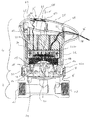
- the circulating pump unit shown consists essentially of two parts, namely a pump 2 and an electric drive motor 4.
- the pump 2 has a pump housing 6, which is preferably formed as a casting of metal.
- the pump housing 6 has an input 10 and an output 12 in a known manner.
- the pump housing 6 has in its interior further in a known manner the required flow paths to an impeller 8 out and away from the impeller 8 to the output 12.
- the impeller 8 rotates in a rotor space, which is formed between the pump housing 6 and the split pot described below.
- the impeller 8 is fixedly connected to a rotor 14 of the drive motor 4.
- the rotor 14 is preferably a permanent magnet rotor.
- the electric drive motor 4 is designed as a wet-running electric motor and has a separation cap 16 formed as a split pot, which is the rotor chamber, in which the rotor 14 is arranged with the impeller 8, fluid-tight from a stator, in which the stator 18 of the electric drive motor is located , separates.
- the motor shown here is designed as a spherical motor. That is, the split pot 16 has a dome-shaped shape and the rotor 14 is rotatably mounted centrally on a ball 20.
- the separation cap 16 has a curvature concentric with the ball 20.
- the rotor 14 is at its outer periphery Correspondingly shaped so that it can rotate around the longitudinal axis X in the interior of the separation cap 16 and can pivot about a certain amount transverse to the longitudinal axis X.
- inventive principle described below of the design of the electric drive motor can also be used with other motors.
- the electric drive motor 4 has a motor housing 22, which is formed in this case of two housing parts 22a and 22b.
- the Motogehotuse 22 represents a combined stator and electronics housing, which in addition to the stator 18, the required engine electronics, which is shown here in the form of the printed circuit board 34 accommodated.
- the motor housing 22 has a first axial end 24, at which it is connected to the pump housing 6. At the second axial end 26 opposite the direction of the longitudinal axis X, the motor housing 22 is closed by a cover 28.
- the longitudinal or rotational axis X is the longitudinal axis of the pump unit, which corresponds to the axis of rotation of the rotor 14 and the impeller 8.
- the first housing part 22 a which is connected to the pump housing 6, is integrally formed with the separating cap 16, so that the separating cap 16 closes the interior of the housing part 22 a to the first axial end 24.
- a total pot-shaped or cup-shaped motor housing is created by the tubular or annular peripheral wall of the motor housing 22 and the separating cap 16 forming the bottom.
- the first housing part 22a of the motor housing 22 has an annular projection 30, which is overlapped by a union nut 32 which is screwed to the pump housing 6.
- a releasable connection of the electric drive motor 4 and the motor housing 22 with the pump 2 and the pump housing 6 is created.
- the first housing part 22a is circumferentially overlapped by the second housing part 22b, wherein the second housing part 22b is pressed or pushed with its inner circumference on the outer circumference of the first housing part 22a.
- the union nut 32 is placed on the first housing part 22a before placing the second housing part 22b.
- the second housing part 22b thus engages over the union nut 32 so that it is captively secured to the first housing part 22.
- the housing parts 22a and 22b of the motor housing 22 together enclose an interior, in which the stator 18 and a printed circuit board 34 are arranged with the engine electronics.
- the printed circuit board 34 contacts the stator coils of the stator 18 and carries electrical or electronic components for controlling the drive motor.
- connection cable 36 Also connected to the printed circuit board 34 is an electrical connecting cable 36, which is guided through an opening 38 out of the motor housing 22 to the outside.
- the opening 38 is located between the motor housing 22 and the cover 28, so that the connection cable 36 can be inserted into the motor housing 22 before closing the cover 28.
- a potting compound 40 which is shown hatched in the drawing.
- the potting compound 40 fills a region adjacent to the first axial end 24 in the interior of the motor housing 22 such that the entire stator 18 and the printed circuit board 34 are completely enveloped by the potting compound 40 with the electrical or electronic components.
- the potting compound 40 is filled in the stator housing 22 through an opening 42 at the first axial end 26 prior to closing the lid 28.
- the opening 42 extends over the entire end face, that is over the entire cross section of the motor housing 22, at the second axial end 26.
- the opening 42 is defined by the axial end edge of the peripheral wall of the housing part 22b or limited.
- the motor housing 22 extends from the first axial end 24 to the second axial end 26 in cross section with respect to the longitudinal axis X. This allows a very large opening 42, through which the potting compound 40 can be filled.
- the potting compound 40 does not fill the interior of the motor housing 22 up to the edge of the opening 42 or to the second axial end 26. This has manufacturing advantages, since so the amount of the potting compound 40 does not have to be precisely metered.
- the potting compound 40 can be easily poured into the opening 42 at the top, until the interior of the motor housing 22 is largely filled without the potting compound overflows over the top edge of the opening 42. A shrinkage of the potting compound during solidification is not a problem. It is only essential that all electrical or electronic components are completely covered by the potting compound 40.
- potting compound 40 is preferably a resin or synthetic resin material, such as epoxy resin, for use.
- the casting compound may be an electrocasting resin based on two components, for example polyurethane.
- the potting compound 40 further fixes the connection cable 36 in the interior of the motor housing 22, so that the potting compound 40 acts as a strain relief and an additional strain relief is unnecessary.
- the potting compound 40 encloses the insulation or sheath of the connection cable 36 over a certain length, so that a non-positive and / or material connection between the potting compound 40 and the outside of the connection line 36 is produced.
- the connecting line 36 could, for example, also be provided with a knot or other undercuts on the outer circumference, which are encompassed by the potting compound 40, so that a positive connection between the potting compound 40 and the connecting cable 36 can be achieved.
- the potting compound 40 additionally secures the connection between the two housing parts 22a and 22b of the motor housing 22.
- the housing part 22b of the motor housing 22 has an inwardly directed circumferential projection 44 at its end which overlaps the first housing part 22a, which outer circumference of the first Housing part 22a comes to rest. Since the entire interior is filled in this region of the motor housing 22 with the potting compound 40, the potting compound 40 engages over the second axial end 26 facing circumferential end edge of the projection 44, so that the second housing part 22b no longer from the first housing part 22a in the axial direction X can be deducted. About the potting compound 40 thus a no longer destructively releasable connection between the housing parts 22a and 22b is created.
- a display element 56 in the form of a light-emitting diode and an operating element 58 in the form of a button are arranged in the cover 28.
- the control and display elements 56, 58 are arranged on a circuit board 60 located on the inside of the cover 28, which is connected via a cable connection in the form of the connecting cable 62 to the electronics on the printed circuit board 34.
- the connecting cable 62 is electrically conductively connected to the printed circuit board 34 and also cast into the potting compound 40.
- the connection cable 62 is electrically connected via a plug connection 64 to the printed circuit board 60.
- the connector 64 makes it possible first to infuse the connection cable 60 with the circuit board 34 in the potting compound 40 and connect the connection cable 62 only after pouring prior to assembly of the cover 28 with the circuit board 60.
- the connecting cable 62 is sufficiently long, wherein the excess length of the connecting cable 62 then remains in the space between the potting compound 40 and the cover 28. It should be understood, however, that the invention is Even without these controls and indicators 56, 58 could be realized.
- the connecting cable 62 for example, fixedly arranged plug contacts could also be arranged in the motor housing 22, which engage electrically with the printed circuit board 60 when the cover 28 is put on.
- connection of the cover 28 with the motor housing 22 and its second part 22b is also designed so that it is virtually no longer destructive solvable.
- This is realized by one or more locking tongues 46 and 48 located in the interior.
- the at least one latching tongue 46 is integrally formed with the cover 28 and extends inside the lid 28 from the lid, starting in the interior of the part 22b of the housing 22. There enters a locking projection 50 with a recess in the locking tongue 46 positively engages.
- the at least one latching tongue 48 is formed integrally with the housing part 22b of the housing 22 and extends from the motor housing 22 to the cover 26 into its interior and enters there in a corresponding manner with a latching projection 52 into engagement.
- the locking connections between the latching tongues 46, 48 and the latching projections 50, 52 are thus located after fixing the cover 28 to the motor housing 22 in the interior of the space enclosed by the motor housing 22 and the cover 28, the locking tongues 46 and 48 can be from the outside can no longer reach and so can not be disengaged from the locking projections 50, 52.
- the locking tongues 46 and 48 can be from the outside can no longer reach and so can not be disengaged from the locking projections 50, 52.
- the assembly of the drive motor 4, as described above, is carried out in such a way that first on the housing part 22a the union nut 32 is placed. Subsequently, the second housing part 22b is clamped to the first housing part 22a pushed, whereby the union nut 32 is fixed in the axial direction X on the motor housing 22. Subsequently, the stator 18 is inserted through the opening 42 in the motor housing 22 and fixed on the outer circumference of the Trennkalotte 16 detent. For this purpose, catch hooks 54 (only one can be seen in the figure) engage in corresponding recesses on the stator 18, so that the stator 18 is fixed in a form-fitting manner to the separating cap 16.
- the stator 18 is spaced from the inner circumference of the peripheral wall of the housing 22, that is, it is not clamped on the inner circumference of the motor housing 22.
- the printed circuit board 34 with the motor electronics, to which the connecting cable 36 is already connected.
- the motor housing 22 is vertically aligned with its longitudinal axis X and it is cast from above the potting compound 40 until the circuit board 34 is sufficiently covered and thus the lower part of the motor housing 22 is filled in its interior with the potting compound 40.
- the connecting cable 36 extends upward, that is, in a direction substantially parallel to the longitudinal axis X of the potting compound 40 out and is deflected only in the space between the surface of the potting compound 40 and the subsequently als simplifyden cover 28 in the transverse direction.
- the cover 28 is placed on the motor housing 22 in the manner described above, wherein the connecting cable 36 is guided through the opening 38 which is formed between the motor housing 22 and the cover 28 to the outside. Since a very simple gravitational, pressure-free pouring of the potting compound 40 takes place, the assembly is very simple. In addition, no additional seals between the cover 28 and the motor housing 22 are required.
Landscapes
- Engineering & Computer Science (AREA)
- Mechanical Engineering (AREA)
- General Engineering & Computer Science (AREA)
- Power Engineering (AREA)
- Microelectronics & Electronic Packaging (AREA)
- Manufacturing & Machinery (AREA)
- Structures Of Non-Positive Displacement Pumps (AREA)
- Motor Or Generator Frames (AREA)
Priority Applications (3)
| Application Number | Priority Date | Filing Date | Title |
|---|---|---|---|
| EP16168323.0A EP3242032B1 (fr) | 2016-05-04 | 2016-05-04 | Pompe ä entrefer dans laquelle aussi bien le stator du moteur que l'unité électronique sont enrobés |
| US15/581,096 US10833554B2 (en) | 2016-05-04 | 2017-04-28 | Circulation pump assembly |
| CN201710307997.9A CN107453520B (zh) | 2016-05-04 | 2017-05-04 | 循环泵机组 |
Applications Claiming Priority (1)
| Application Number | Priority Date | Filing Date | Title |
|---|---|---|---|
| EP16168323.0A EP3242032B1 (fr) | 2016-05-04 | 2016-05-04 | Pompe ä entrefer dans laquelle aussi bien le stator du moteur que l'unité électronique sont enrobés |
Publications (2)
| Publication Number | Publication Date |
|---|---|
| EP3242032A1 true EP3242032A1 (fr) | 2017-11-08 |
| EP3242032B1 EP3242032B1 (fr) | 2019-11-06 |
Family
ID=55910892
Family Applications (1)
| Application Number | Title | Priority Date | Filing Date |
|---|---|---|---|
| EP16168323.0A Active EP3242032B1 (fr) | 2016-05-04 | 2016-05-04 | Pompe ä entrefer dans laquelle aussi bien le stator du moteur que l'unité électronique sont enrobés |
Country Status (3)
| Country | Link |
|---|---|
| US (1) | US10833554B2 (fr) |
| EP (1) | EP3242032B1 (fr) |
| CN (1) | CN107453520B (fr) |
Families Citing this family (7)
| Publication number | Priority date | Publication date | Assignee | Title |
|---|---|---|---|---|
| US20170082070A1 (en) * | 2012-04-17 | 2017-03-23 | Timothy J. Miller | Turbopump with a single piece housing and a smooth enamel glass surface |
| EP3603898B1 (fr) * | 2018-08-03 | 2021-04-14 | Andreas Stihl AG & Co. KG | Appareil de travail portatif |
| CN110971060A (zh) * | 2018-09-28 | 2020-04-07 | 广东威灵电机制造有限公司 | 电机端盖及电机 |
| KR102221809B1 (ko) * | 2019-09-16 | 2021-03-03 | 주식회사 코아비스 | 제어부 일체형 모터 및 이를 포함한 워터 펌프 |
| DE102019130722A1 (de) * | 2019-11-14 | 2021-05-20 | Fte Automotive Gmbh | Flüssigkeitspumpe |
| IT202000004909A1 (it) * | 2020-03-09 | 2021-09-09 | Dab Pumps Spa | Elettropompa ad assemblaggio e manutenzione facilitata |
| DE102025122058A1 (de) * | 2024-08-02 | 2026-02-05 | Hanon Systems Efp Deutschland Gmbh | Pumpengehäuse und pumpe |
Citations (4)
| Publication number | Priority date | Publication date | Assignee | Title |
|---|---|---|---|---|
| JP2001304166A (ja) * | 2000-04-27 | 2001-10-31 | Aisan Ind Co Ltd | 磁気結合ポンプ |
| JP2004183595A (ja) * | 2002-12-05 | 2004-07-02 | Calsonic Kansei Corp | 電動ブラシレスウォータポンプ |
| WO2012062638A2 (fr) * | 2010-11-11 | 2012-05-18 | Grundfos Holding A/S | Moteur électrique à bain d'huile et ensemble pompe |
| US20130028765A1 (en) * | 2011-07-25 | 2013-01-31 | Nidec Sankyo Corporation | Vortex pump device |
Family Cites Families (25)
| Publication number | Priority date | Publication date | Assignee | Title |
|---|---|---|---|---|
| US2689529A (en) * | 1952-04-30 | 1954-09-21 | Gen Electric | Submersible pump-motor |
| US2883566A (en) * | 1955-10-27 | 1959-04-21 | American Mach & Foundry | Submersible dynamo electric machine |
| US3041976A (en) * | 1958-07-02 | 1962-07-03 | Smith Corp A O | Motor pump construction |
| US3135885A (en) * | 1959-03-26 | 1964-06-02 | Smith Corp A O | Dynamoelectric machines |
| US3210577A (en) * | 1962-07-31 | 1965-10-05 | Gen Electric | Encapsulated electric motor |
| US3555319A (en) * | 1969-03-05 | 1971-01-12 | Franklin Electric Co Inc | Submersible electric motor |
| US4456844A (en) * | 1981-01-17 | 1984-06-26 | Mitsubishi Denki Kabushiki Kaisha | Submergible motor construction |
| US4451750A (en) * | 1981-02-03 | 1984-05-29 | Elektro-Mechanik Gmbh | Protective arrangement for a plug-connected electric motor sealed against pressure, vapors and radiation |
| US4387313A (en) * | 1981-04-22 | 1983-06-07 | Mitsubishi Denki Kabushiki Kaisha | Molded submersible motor |
| JPS5996843A (ja) * | 1982-11-19 | 1984-06-04 | Hitachi Ltd | 水中モータ |
| CA1285357C (fr) * | 1989-01-20 | 1991-07-02 | Richard Mcavena | Methode pour rendre un moteur electrique etanche a l'eau |
| DE29505575U1 (de) * | 1994-05-04 | 1995-06-14 | Halm, Richard, 73666 Baltmannsweiler | Naßläufer-Spaltrohrmotor für Pumpen |
| US5577895A (en) * | 1995-02-24 | 1996-11-26 | Fe Petro Inc. | Submerged pump unit having a variable length pipe assembly |
| US5889343A (en) * | 1997-08-01 | 1999-03-30 | Reliance Electric Industrial Company | Electromechanical machine having improved lead wire sealing arrangement |
| DE10033862C2 (de) * | 2000-07-12 | 2002-07-11 | Buhler Motor Gmbh | Elektromotor, insbesondere bürstenloser Pumpenmotor |
| DE10254670A1 (de) * | 2002-11-22 | 2004-06-24 | Minebea Co., Ltd. | Elektromotor für einen Pumpenantrieb |
| US7042124B2 (en) * | 2003-10-03 | 2006-05-09 | Franklin Electric Co., Inc. | Electric motors for washdown, food processing, and chemical applications |
| US20050074548A1 (en) * | 2003-10-03 | 2005-04-07 | Puterbaugh David K. | Method and apparatus for encapsulating electric motors used in washdown, food processing, and chemical applications |
| US7625187B2 (en) * | 2005-08-24 | 2009-12-01 | Johnson Pumps Of America Inc. | Submersible pump with integrated liquid level sensing and control system |
| JP4774888B2 (ja) * | 2005-09-27 | 2011-09-14 | 日本電産株式会社 | モータ |
| DE102006008423A1 (de) * | 2006-02-23 | 2007-08-30 | Wilo Ag | Motorkreiselpumpe |
| DE102007016255B4 (de) * | 2006-04-28 | 2012-11-29 | Bühler Motor GmbH | Kreiselpumpe |
| DE102008062561A1 (de) * | 2008-12-16 | 2010-06-24 | Maxon Motor Ag | Bausatz für einen Elektromotor mit einem Drehwinkelgeber |
| WO2011022483A1 (fr) * | 2009-08-18 | 2011-02-24 | Itt Manufacturing Enterprises, Inc. | Pompe submersible encapsulée |
| JP5033252B1 (ja) * | 2011-04-14 | 2012-09-26 | 日機装株式会社 | キャンドモータポンプ及びそのステータ室内に充填材を充填する方法 |
-
2016
- 2016-05-04 EP EP16168323.0A patent/EP3242032B1/fr active Active
-
2017
- 2017-04-28 US US15/581,096 patent/US10833554B2/en not_active Expired - Fee Related
- 2017-05-04 CN CN201710307997.9A patent/CN107453520B/zh not_active Expired - Fee Related
Patent Citations (4)
| Publication number | Priority date | Publication date | Assignee | Title |
|---|---|---|---|---|
| JP2001304166A (ja) * | 2000-04-27 | 2001-10-31 | Aisan Ind Co Ltd | 磁気結合ポンプ |
| JP2004183595A (ja) * | 2002-12-05 | 2004-07-02 | Calsonic Kansei Corp | 電動ブラシレスウォータポンプ |
| WO2012062638A2 (fr) * | 2010-11-11 | 2012-05-18 | Grundfos Holding A/S | Moteur électrique à bain d'huile et ensemble pompe |
| US20130028765A1 (en) * | 2011-07-25 | 2013-01-31 | Nidec Sankyo Corporation | Vortex pump device |
Also Published As
| Publication number | Publication date |
|---|---|
| CN107453520A (zh) | 2017-12-08 |
| EP3242032B1 (fr) | 2019-11-06 |
| US10833554B2 (en) | 2020-11-10 |
| CN107453520B (zh) | 2020-12-04 |
| US20170324298A1 (en) | 2017-11-09 |
Similar Documents
| Publication | Publication Date | Title |
|---|---|---|
| EP3242032B1 (fr) | Pompe ä entrefer dans laquelle aussi bien le stator du moteur que l'unité électronique sont enrobés | |
| EP0698183B1 (fr) | Ensemble pompe et moteur electrique | |
| EP3411940B1 (fr) | Moteur électrique destiné à une pompe à fluide, famille de moteurs modulaire pour former des pompes à fluide différentes comportant plusieurs desdits moteurs électriques et procédé de fabrication | |
| EP2500575B1 (fr) | Pompe de recirculation de chauffage | |
| EP2500577B1 (fr) | Pompe de recirculation de chauffage | |
| EP2320092B1 (fr) | Unité de pompage | |
| DE4440238B4 (de) | Brennstoffpumpe | |
| EP3245712B1 (fr) | Agrégat auxiliaire électrique d'un véhicule | |
| EP3710706B1 (fr) | Pompe à eau et procédé de fabrication d'une pompe à eau | |
| EP1175722B1 (fr) | Unite d'entrainement electrique | |
| DE102014009103B4 (de) | Drehmomentsensor-abdeckung | |
| WO2012123234A1 (fr) | Pompe de recirculation de la chaleur | |
| EP3378143B1 (fr) | Couvercle de boîtier pour machine électrique | |
| DE102013020094A1 (de) | Elektromotor, insbesondere Kühlerlüftermotor | |
| WO2019121102A1 (fr) | Pompe à gérotors et procédé de fabrication de celle-ci | |
| WO2015071030A1 (fr) | Module électronique pour dispositif d'allumage | |
| DE102013208746A1 (de) | Stator für eine elektrische Maschine, der sich konzentrisch um eine Mittelachse erstreckt und Verfahren zur Herstellung einer solchen | |
| EP2182219B1 (fr) | Moto-pompe centrifuge | |
| DE102014225856A1 (de) | Sensoreinrichtung | |
| DE202008017587U1 (de) | Rotor | |
| WO2018162620A1 (fr) | Moteur électrique | |
| WO2003088453A1 (fr) | Groupe moteur comportant un palier fixe | |
| WO2019091762A1 (fr) | Procédé d'assemblage d'une pompe à eau | |
| DE102004047637A1 (de) | Elektrisch betriebene Pumpe mit Außenrotor | |
| DE4203482A1 (de) | Tauchpumpenaggregat |
Legal Events
| Date | Code | Title | Description |
|---|---|---|---|
| PUAI | Public reference made under article 153(3) epc to a published international application that has entered the european phase |
Free format text: ORIGINAL CODE: 0009012 |
|
| STAA | Information on the status of an ep patent application or granted ep patent |
Free format text: STATUS: THE APPLICATION HAS BEEN PUBLISHED |
|
| AK | Designated contracting states |
Kind code of ref document: A1 Designated state(s): AL AT BE BG CH CY CZ DE DK EE ES FI FR GB GR HR HU IE IS IT LI LT LU LV MC MK MT NL NO PL PT RO RS SE SI SK SM TR |
|
| AX | Request for extension of the european patent |
Extension state: BA ME |
|
| STAA | Information on the status of an ep patent application or granted ep patent |
Free format text: STATUS: REQUEST FOR EXAMINATION WAS MADE |
|
| 17P | Request for examination filed |
Effective date: 20180508 |
|
| RBV | Designated contracting states (corrected) |
Designated state(s): AL AT BE BG CH CY CZ DE DK EE ES FI FR GB GR HR HU IE IS IT LI LT LU LV MC MK MT NL NO PL PT RO RS SE SI SK SM TR |
|
| GRAP | Despatch of communication of intention to grant a patent |
Free format text: ORIGINAL CODE: EPIDOSNIGR1 |
|
| STAA | Information on the status of an ep patent application or granted ep patent |
Free format text: STATUS: GRANT OF PATENT IS INTENDED |
|
| INTG | Intention to grant announced |
Effective date: 20190523 |
|
| RIN1 | Information on inventor provided before grant (corrected) |
Inventor name: BROESAMLE, PINO Inventor name: BLASER, GEORG |
|
| GRAS | Grant fee paid |
Free format text: ORIGINAL CODE: EPIDOSNIGR3 |
|
| GRAA | (expected) grant |
Free format text: ORIGINAL CODE: 0009210 |
|
| STAA | Information on the status of an ep patent application or granted ep patent |
Free format text: STATUS: THE PATENT HAS BEEN GRANTED |
|
| AK | Designated contracting states |
Kind code of ref document: B1 Designated state(s): AL AT BE BG CH CY CZ DE DK EE ES FI FR GB GR HR HU IE IS IT LI LT LU LV MC MK MT NL NO PL PT RO RS SE SI SK SM TR |
|
| REG | Reference to a national code |
Ref country code: GB Ref legal event code: FG4D Free format text: NOT ENGLISH |
|
| REG | Reference to a national code |
Ref country code: CH Ref legal event code: EP Ref country code: AT Ref legal event code: REF Ref document number: 1199062 Country of ref document: AT Kind code of ref document: T Effective date: 20191115 |
|
| REG | Reference to a national code |
Ref country code: IE Ref legal event code: FG4D Free format text: LANGUAGE OF EP DOCUMENT: GERMAN |
|
| REG | Reference to a national code |
Ref country code: DE Ref legal event code: R096 Ref document number: 502016007388 Country of ref document: DE |
|
| REG | Reference to a national code |
Ref country code: NL Ref legal event code: MP Effective date: 20191106 |
|
| REG | Reference to a national code |
Ref country code: LT Ref legal event code: MG4D |
|
| PG25 | Lapsed in a contracting state [announced via postgrant information from national office to epo] |
Ref country code: LT Free format text: LAPSE BECAUSE OF FAILURE TO SUBMIT A TRANSLATION OF THE DESCRIPTION OR TO PAY THE FEE WITHIN THE PRESCRIBED TIME-LIMIT Effective date: 20191106 Ref country code: PL Free format text: LAPSE BECAUSE OF FAILURE TO SUBMIT A TRANSLATION OF THE DESCRIPTION OR TO PAY THE FEE WITHIN THE PRESCRIBED TIME-LIMIT Effective date: 20191106 Ref country code: NL Free format text: LAPSE BECAUSE OF FAILURE TO SUBMIT A TRANSLATION OF THE DESCRIPTION OR TO PAY THE FEE WITHIN THE PRESCRIBED TIME-LIMIT Effective date: 20191106 Ref country code: GR Free format text: LAPSE BECAUSE OF FAILURE TO SUBMIT A TRANSLATION OF THE DESCRIPTION OR TO PAY THE FEE WITHIN THE PRESCRIBED TIME-LIMIT Effective date: 20200207 Ref country code: BG Free format text: LAPSE BECAUSE OF FAILURE TO SUBMIT A TRANSLATION OF THE DESCRIPTION OR TO PAY THE FEE WITHIN THE PRESCRIBED TIME-LIMIT Effective date: 20200206 Ref country code: FI Free format text: LAPSE BECAUSE OF FAILURE TO SUBMIT A TRANSLATION OF THE DESCRIPTION OR TO PAY THE FEE WITHIN THE PRESCRIBED TIME-LIMIT Effective date: 20191106 Ref country code: PT Free format text: LAPSE BECAUSE OF FAILURE TO SUBMIT A TRANSLATION OF THE DESCRIPTION OR TO PAY THE FEE WITHIN THE PRESCRIBED TIME-LIMIT Effective date: 20200306 Ref country code: NO Free format text: LAPSE BECAUSE OF FAILURE TO SUBMIT A TRANSLATION OF THE DESCRIPTION OR TO PAY THE FEE WITHIN THE PRESCRIBED TIME-LIMIT Effective date: 20200206 Ref country code: LV Free format text: LAPSE BECAUSE OF FAILURE TO SUBMIT A TRANSLATION OF THE DESCRIPTION OR TO PAY THE FEE WITHIN THE PRESCRIBED TIME-LIMIT Effective date: 20191106 Ref country code: SE Free format text: LAPSE BECAUSE OF FAILURE TO SUBMIT A TRANSLATION OF THE DESCRIPTION OR TO PAY THE FEE WITHIN THE PRESCRIBED TIME-LIMIT Effective date: 20191106 |
|
| PG25 | Lapsed in a contracting state [announced via postgrant information from national office to epo] |
Ref country code: IS Free format text: LAPSE BECAUSE OF FAILURE TO SUBMIT A TRANSLATION OF THE DESCRIPTION OR TO PAY THE FEE WITHIN THE PRESCRIBED TIME-LIMIT Effective date: 20200306 Ref country code: HR Free format text: LAPSE BECAUSE OF FAILURE TO SUBMIT A TRANSLATION OF THE DESCRIPTION OR TO PAY THE FEE WITHIN THE PRESCRIBED TIME-LIMIT Effective date: 20191106 Ref country code: RS Free format text: LAPSE BECAUSE OF FAILURE TO SUBMIT A TRANSLATION OF THE DESCRIPTION OR TO PAY THE FEE WITHIN THE PRESCRIBED TIME-LIMIT Effective date: 20191106 |
|
| PG25 | Lapsed in a contracting state [announced via postgrant information from national office to epo] |
Ref country code: AL Free format text: LAPSE BECAUSE OF FAILURE TO SUBMIT A TRANSLATION OF THE DESCRIPTION OR TO PAY THE FEE WITHIN THE PRESCRIBED TIME-LIMIT Effective date: 20191106 |
|
| PG25 | Lapsed in a contracting state [announced via postgrant information from national office to epo] |
Ref country code: CZ Free format text: LAPSE BECAUSE OF FAILURE TO SUBMIT A TRANSLATION OF THE DESCRIPTION OR TO PAY THE FEE WITHIN THE PRESCRIBED TIME-LIMIT Effective date: 20191106 Ref country code: ES Free format text: LAPSE BECAUSE OF FAILURE TO SUBMIT A TRANSLATION OF THE DESCRIPTION OR TO PAY THE FEE WITHIN THE PRESCRIBED TIME-LIMIT Effective date: 20191106 Ref country code: EE Free format text: LAPSE BECAUSE OF FAILURE TO SUBMIT A TRANSLATION OF THE DESCRIPTION OR TO PAY THE FEE WITHIN THE PRESCRIBED TIME-LIMIT Effective date: 20191106 Ref country code: RO Free format text: LAPSE BECAUSE OF FAILURE TO SUBMIT A TRANSLATION OF THE DESCRIPTION OR TO PAY THE FEE WITHIN THE PRESCRIBED TIME-LIMIT Effective date: 20191106 Ref country code: DK Free format text: LAPSE BECAUSE OF FAILURE TO SUBMIT A TRANSLATION OF THE DESCRIPTION OR TO PAY THE FEE WITHIN THE PRESCRIBED TIME-LIMIT Effective date: 20191106 |
|
| REG | Reference to a national code |
Ref country code: DE Ref legal event code: R097 Ref document number: 502016007388 Country of ref document: DE |
|
| PG25 | Lapsed in a contracting state [announced via postgrant information from national office to epo] |
Ref country code: SK Free format text: LAPSE BECAUSE OF FAILURE TO SUBMIT A TRANSLATION OF THE DESCRIPTION OR TO PAY THE FEE WITHIN THE PRESCRIBED TIME-LIMIT Effective date: 20191106 Ref country code: SM Free format text: LAPSE BECAUSE OF FAILURE TO SUBMIT A TRANSLATION OF THE DESCRIPTION OR TO PAY THE FEE WITHIN THE PRESCRIBED TIME-LIMIT Effective date: 20191106 |
|
| PLBE | No opposition filed within time limit |
Free format text: ORIGINAL CODE: 0009261 |
|
| STAA | Information on the status of an ep patent application or granted ep patent |
Free format text: STATUS: NO OPPOSITION FILED WITHIN TIME LIMIT |
|
| 26N | No opposition filed |
Effective date: 20200807 |
|
| PG25 | Lapsed in a contracting state [announced via postgrant information from national office to epo] |
Ref country code: SI Free format text: LAPSE BECAUSE OF FAILURE TO SUBMIT A TRANSLATION OF THE DESCRIPTION OR TO PAY THE FEE WITHIN THE PRESCRIBED TIME-LIMIT Effective date: 20191106 |
|
| PG25 | Lapsed in a contracting state [announced via postgrant information from national office to epo] |
Ref country code: CH Free format text: LAPSE BECAUSE OF NON-PAYMENT OF DUE FEES Effective date: 20200531 Ref country code: LI Free format text: LAPSE BECAUSE OF NON-PAYMENT OF DUE FEES Effective date: 20200531 Ref country code: MC Free format text: LAPSE BECAUSE OF FAILURE TO SUBMIT A TRANSLATION OF THE DESCRIPTION OR TO PAY THE FEE WITHIN THE PRESCRIBED TIME-LIMIT Effective date: 20191106 |
|
| REG | Reference to a national code |
Ref country code: BE Ref legal event code: MM Effective date: 20200531 |
|
| PG25 | Lapsed in a contracting state [announced via postgrant information from national office to epo] |
Ref country code: LU Free format text: LAPSE BECAUSE OF NON-PAYMENT OF DUE FEES Effective date: 20200504 |
|
| PG25 | Lapsed in a contracting state [announced via postgrant information from national office to epo] |
Ref country code: IE Free format text: LAPSE BECAUSE OF NON-PAYMENT OF DUE FEES Effective date: 20200504 |
|
| PG25 | Lapsed in a contracting state [announced via postgrant information from national office to epo] |
Ref country code: BE Free format text: LAPSE BECAUSE OF NON-PAYMENT OF DUE FEES Effective date: 20200531 |
|
| PG25 | Lapsed in a contracting state [announced via postgrant information from national office to epo] |
Ref country code: TR Free format text: LAPSE BECAUSE OF FAILURE TO SUBMIT A TRANSLATION OF THE DESCRIPTION OR TO PAY THE FEE WITHIN THE PRESCRIBED TIME-LIMIT Effective date: 20191106 Ref country code: MT Free format text: LAPSE BECAUSE OF FAILURE TO SUBMIT A TRANSLATION OF THE DESCRIPTION OR TO PAY THE FEE WITHIN THE PRESCRIBED TIME-LIMIT Effective date: 20191106 Ref country code: CY Free format text: LAPSE BECAUSE OF FAILURE TO SUBMIT A TRANSLATION OF THE DESCRIPTION OR TO PAY THE FEE WITHIN THE PRESCRIBED TIME-LIMIT Effective date: 20191106 |
|
| PG25 | Lapsed in a contracting state [announced via postgrant information from national office to epo] |
Ref country code: MK Free format text: LAPSE BECAUSE OF FAILURE TO SUBMIT A TRANSLATION OF THE DESCRIPTION OR TO PAY THE FEE WITHIN THE PRESCRIBED TIME-LIMIT Effective date: 20191106 |
|
| REG | Reference to a national code |
Ref country code: AT Ref legal event code: MM01 Ref document number: 1199062 Country of ref document: AT Kind code of ref document: T Effective date: 20210504 |
|
| PG25 | Lapsed in a contracting state [announced via postgrant information from national office to epo] |
Ref country code: AT Free format text: LAPSE BECAUSE OF NON-PAYMENT OF DUE FEES Effective date: 20210504 |
|
| REG | Reference to a national code |
Ref country code: DE Ref legal event code: R082 Ref document number: 502016007388 Country of ref document: DE |
|
| PGFP | Annual fee paid to national office [announced via postgrant information from national office to epo] |
Ref country code: IT Payment date: 20230526 Year of fee payment: 8 Ref country code: FR Payment date: 20230526 Year of fee payment: 8 Ref country code: DE Payment date: 20230519 Year of fee payment: 8 |
|
| PGFP | Annual fee paid to national office [announced via postgrant information from national office to epo] |
Ref country code: GB Payment date: 20230524 Year of fee payment: 8 |
|
| REG | Reference to a national code |
Ref country code: DE Ref legal event code: R119 Ref document number: 502016007388 Country of ref document: DE |
|
| GBPC | Gb: european patent ceased through non-payment of renewal fee |
Effective date: 20240504 |
|
| PG25 | Lapsed in a contracting state [announced via postgrant information from national office to epo] |
Ref country code: DE Free format text: LAPSE BECAUSE OF NON-PAYMENT OF DUE FEES Effective date: 20241203 |
|
| PG25 | Lapsed in a contracting state [announced via postgrant information from national office to epo] |
Ref country code: FR Free format text: LAPSE BECAUSE OF NON-PAYMENT OF DUE FEES Effective date: 20240531 |
|
| PG25 | Lapsed in a contracting state [announced via postgrant information from national office to epo] |
Ref country code: GB Free format text: LAPSE BECAUSE OF NON-PAYMENT OF DUE FEES Effective date: 20240504 Ref country code: IT Free format text: LAPSE BECAUSE OF NON-PAYMENT OF DUE FEES Effective date: 20240504 |