EP3242033B1 - Procédé de fonctionnement d'un groupe motopompe à commande électrique - Google Patents
Procédé de fonctionnement d'un groupe motopompe à commande électrique Download PDFInfo
- Publication number
- EP3242033B1 EP3242033B1 EP16207574.1A EP16207574A EP3242033B1 EP 3242033 B1 EP3242033 B1 EP 3242033B1 EP 16207574 A EP16207574 A EP 16207574A EP 3242033 B1 EP3242033 B1 EP 3242033B1
- Authority
- EP
- European Patent Office
- Prior art keywords
- setting parameters
- controller
- predetermined time
- pump unit
- check
- Prior art date
- Legal status (The legal status is an assumption and is not a legal conclusion. Google has not performed a legal analysis and makes no representation as to the accuracy of the status listed.)
- Active
Links
Images
Classifications
-
- F—MECHANICAL ENGINEERING; LIGHTING; HEATING; WEAPONS; BLASTING
- F04—POSITIVE - DISPLACEMENT MACHINES FOR LIQUIDS; PUMPS FOR LIQUIDS OR ELASTIC FLUIDS
- F04D—NON-POSITIVE-DISPLACEMENT PUMPS
- F04D13/00—Pumping installations or systems
- F04D13/02—Units comprising pumps and their driving means
- F04D13/06—Units comprising pumps and their driving means the pump being electrically driven
-
- F—MECHANICAL ENGINEERING; LIGHTING; HEATING; WEAPONS; BLASTING
- F04—POSITIVE - DISPLACEMENT MACHINES FOR LIQUIDS; PUMPS FOR LIQUIDS OR ELASTIC FLUIDS
- F04D—NON-POSITIVE-DISPLACEMENT PUMPS
- F04D15/00—Control, e.g. regulation, of pumps, pumping installations or systems
- F04D15/0088—Testing machines
-
- F—MECHANICAL ENGINEERING; LIGHTING; HEATING; WEAPONS; BLASTING
- F04—POSITIVE - DISPLACEMENT MACHINES FOR LIQUIDS; PUMPS FOR LIQUIDS OR ELASTIC FLUIDS
- F04D—NON-POSITIVE-DISPLACEMENT PUMPS
- F04D15/00—Control, e.g. regulation, of pumps, pumping installations or systems
- F04D15/0094—Indicators of rotational movement
-
- F—MECHANICAL ENGINEERING; LIGHTING; HEATING; WEAPONS; BLASTING
- F05—INDEXING SCHEMES RELATING TO ENGINES OR PUMPS IN VARIOUS SUBCLASSES OF CLASSES F01-F04
- F05D—INDEXING SCHEME FOR ASPECTS RELATING TO NON-POSITIVE-DISPLACEMENT MACHINES OR ENGINES, GAS-TURBINES OR JET-PROPULSION PLANTS
- F05D2270/00—Control
- F05D2270/01—Purpose of the control system
- F05D2270/20—Purpose of the control system to optimize the performance of a machine
-
- F—MECHANICAL ENGINEERING; LIGHTING; HEATING; WEAPONS; BLASTING
- F05—INDEXING SCHEMES RELATING TO ENGINES OR PUMPS IN VARIOUS SUBCLASSES OF CLASSES F01-F04
- F05D—INDEXING SCHEME FOR ASPECTS RELATING TO NON-POSITIVE-DISPLACEMENT MACHINES OR ENGINES, GAS-TURBINES OR JET-PROPULSION PLANTS
- F05D2270/00—Control
- F05D2270/30—Control parameters, e.g. input parameters
- F05D2270/301—Pressure
- F05D2270/3015—Pressure differential pressure
Definitions
- the invention relates to a method for operating an electronically controlled centrifugal pump unit with the features specified in the preamble of claim 1 and to an electronic control of an electric motor-driven centrifugal pump unit for carrying out this method with the features specified in the preamble of claim 7.
- Modern pump units particularly centrifugal pump units driven by an electric motor, have an electric motor connected to a power converter/frequency converter so that the pumps can be operated in a wide range of speeds and thus cover a comparatively large range of performance.
- circulation pump units for example, it is state of the art to drive the pump at any constant speed, but also to control operation according to predetermined pump curves.
- controls are provided which are operated using hydraulic sensors or, if necessary, only based on the electrical values of the motor.
- heating circulation pumps can be operated with constant pressure curves, with constant flow curves, with proportional pressure curves or the like.
- booster pumps not only the target delivery pressure has to be set, but also the switching points at which another pump is switched on or off.
- EP1614903 A1 A pump known from the prior art is disclosed.
- the invention is based on the object of designing a method for operating an electronically controlled centrifugal pump unit in such a way that the above-mentioned problems are avoided as far as possible.
- the electronic control of an electric motor-driven centrifugal pump unit is to be adapted to carry out such a method.
- the method according to the invention for operating an electronically controlled centrifugal pump unit in which setting parameters of the pump can be set in an electronic control system to adapt to the hydraulic requirements of the local installation situation and in which operating data of the pump unit are recorded during operation, is characterized according to the invention in that after a predetermined time it is checked whether all setting parameters have not been changed compared to a presetting and then, if it is determined that the setting parameters have not yet been changed compared to the presetting, a signal is issued to change the setting parameters.
- the method should preferably be automated, i.e. run automatically, by being implemented in the electronic control system, as described further below.
- the basic idea of the invention is to check after a predetermined time whether the setting parameters of the pump unit have ever been changed compared to a preset setting, in order to then emit a signal based on It is clear that a change in the setting parameters should at least be checked.
- a pump unit within the meaning of the invention can in principle be any electric motor-driven centrifugal pump with an electronic control system in which the pump setting parameters can be changed to adapt to the hydraulic requirements of the local installation situation. Typically, these are single- or multi-stage centrifugal pumps controlled by a power converter/frequency converter.
- a pump unit within the meaning of the invention can, however, also be a number of individual pump units that are operated by a common control system, as is the case with pressure boosting systems (e.g. booster pumps).
- the signal emitted can, for example, be used to control an indicator light provided on the pump unit, to emit an acoustic alarm or to transmit a corresponding data set to a cloud-based database or a server of the manufacturer and/or operator of the pump unit.
- the method according to the invention is started with the installation of the pump unit, then the factory presetting of the pump unit is the default setting. Then, after a predetermined time, a check is made as to whether this factory presetting has been changed or not and, if there has been no change, the corresponding signal is emitted.
- the registered operating data is used to check whether the pump unit can be operated in a more energy-efficient range.
- a further development of the method provides for that for the energetic evaluation of the operating data, electrical operating data of the motor, in particular the electrical power of the motor, which is already available on the control side, and hydraulic operating data of the pump, in particular the pressure and/or flow, are used. This makes it possible to analyze the energetic behavior of the pump unit without further data. The hydraulic power resulting from the hydraulic operating data is compared with the electrical power of the motor in order to determine the efficiency of the unit.
- the power of the electric motor is available from the control electronics, and from the hydraulic data a pressure, typically the differential pressure applied by the pump, is usually available via a sensor, so that the hydraulic power can be determined in conjunction with the speed also available on the motor side.
- a pressure typically the differential pressure applied by the pump
- the data from a flow sensor can be used for this purpose.
- the hydraulic power is known to be the product of the differential pressure, the flow rate, the density of the pumped medium and the gravitational acceleration. This data can be used to determine the efficiency of the pump unit either at specific points in time or continuously by evaluating the energy from the operating data.
- the limit value has been set at a maximum of 30%, then only the operating points at which the efficiency factor is less than 0.7 are to be recorded. The total number of operating points to be taken into account is then the predetermined time divided by six minutes.
- the method can not only be used to force the pump unit to operate in an energy-efficient manner, but can also be used to determine and indicate whether the pump unit is significantly under- or over-dimensioned.
- the process can ideally lead to an automatic adjustment of the pump unit's setting parameters, particularly if the pump unit is connected to the Internet, if not only the operating data of the pump unit is transmitted and recorded via an Internet-based network, but also a corresponding adjustment of the setting parameters can be initiated after a network-side check.
- this requires not only a data connection of the pump unit to the Internet-based network, but also the possibility of changing the operating parameters via this network.
- a data set with appropriately adjusted setting parameters can be made available for download on the network side, which the service technician can download to his smartphone, for example, and then read into the electronic motor control on site.
- the process in which the efficiency of the pump unit is checked is carried out continuously during the entire operating time. In view of the large amount of data that then has to be recorded and processed, however, it is In practice, it may be useful to check within a relatively short time after initial commissioning whether the pump unit is running efficiently in terms of energy and then to check this at longer intervals later. In this respect, it is advantageous to choose a predetermined time period in which the operating data is recorded between one hour and seven days.
- the method according to the invention can typically be implemented in existing pump units by means of a software update in the electronic motor control.
- the signal output is then tied to the hardware capabilities of the pump unit.
- a display for example a red indicator light or a yellow flashing light, is activated and alternatively or additionally an acoustic signal is emitted so that everyone who is near the pump unit is aware that there is obviously a need for action.
- the signal is transmitted in the form of a data packet via the internet-based network to a server, which informs the manufacturer or the maintenance company that there is a need for action.
- the data packet contains the location data of the pump unit, as spatial assignment is then possible without access to other personal databases.
- the electronic control of an electric motor-driven centrifugal pump unit is used to carry out the method according to the invention. It has means for setting setting parameters to adapt the pump unit to the hydraulic requirements of the local installation situation. These can be formed by buttons/switches/touch screens on the unit itself, with which the setting parameters can be changed, for example by selecting corresponding control curves or pressure/flow setpoints. However, such means can also be formed wirelessly, for example by means of a mobile computer, typically smartphones or tablets, on which a corresponding software application runs with which this data can be entered and wirelessly transmitted to the electronic control. If the electronic control is connected to a network, these means can also be formed by transmitting corresponding settings over the network.
- the control itself is designed to register or forward operating data of the pump unit.
- the method according to the invention including registration and evaluation of the registered data, can be carried out within the electronic control of the pump unit or at least partially via a network-connected server with which the electronic control is in data connection.
- the electronic control of the pump unit is designed to determine whether the setting parameters have been adjusted compared to a registered setting after a predetermined time and to automatically emit a signal if the setting has not been made. In principle, such a check can be carried out automatically at regular intervals by the Control or continuously.
- this predetermined time begins when the control is put into operation and the registered setting is the factory setting. This ensures that when the pump unit is installed at its destination after delivery by the manufacturer and connected to the power supply network, immediately after this initial commissioning it is at least monitored whether or not the setting parameters have been changed compared to the factory settings.
- the electronic control is further designed to automatically determine whether the pump unit is being operated in an energy-efficient range or not.
- the storage and computing operations required in this regard are more complex, however, which is why they can advantageously also be carried out externally via a network.
- the control advantageously has an interface to a network, preferably to an internet-based network.
- Such an interface can be wired, for example as a LAN connection, but is particularly advantageously designed for wireless data transmission, for example via WLAN or a mobile phone connection.
- the invention provides that the setting parameters are stored in a file in the control system and that only the change in this file is monitored.
- a file in the sense of this invention can also be a group of files or a folder; the crucial point is that the monitoring can be carried out without specifically monitoring the setting parameters themselves, but simply by monitoring the file, which has a changed date when changed.
- the setting parameters of the electronic control are advantageously one or more of the control variables such as flow rate, delivery pressure, speed, power, whereby the hydraulic control variables flow rate and/or delivery pressure can typically be set in the form of control curves.
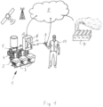
- a pump unit 1 is shown, a so-called booster pump, which is made up of three centrifugal pumps 2 connected in parallel, each of which is driven by a frequency converter-controlled electric motor 3, which pump from a common suction line 4 into a common pressure line 5.
- the pump unit 1 has a higher-level electronic control 6, into which setting parameters, in particular the delivery pressure and the switching on and off points of the individual pumps, can be entered.
- This electronic control has an interface to a network, which is cloud-based.
- the control 6 is equipped with a WLAN module and a mobile radio module, through which it is wirelessly connected to the network of the pump manufacturer 7 via the Internet 8, i.e. the "cloud".
- the electronic control is also equipped with a Bluetooth interface, via which it can communicate with a smartphone 9, via which an operator 10 can query and change the setting parameters available in the control 6.
- the smartphone 9 is also connected to the Internet 8 and thus to the network of the manufacturer 7 via its radio interface.
- the electronic control 6 is designed to check after a predetermined time after the pump unit 1 has started operating whether the setting parameters have been changed compared to the factory settings. These parameters are digitally stored in a file in the control 6, and the control 6 monitors the storage date of the file. From the initial start-up, a timer runs, which is set to 72 hours, for example, so that after this predetermined time has elapsed, a check is made as to whether the storage date of the file has changed or not. If this is not the case, a signal is emitted on the control 6 itself to activate a warning light 11, which emits a flashing signal as a sign that the pump unit 1 has not yet been set.
- a corresponding data signal is sent to the network so that this is noted in the manufacturer's database 7, specifying the GPS data of the location of the pump unit, and at the same time a note appears that this pump unit must be set by a service technician.
- this required setting can be made via the network itself or via the manufacturer 7 or operator.
- a service technician is required, i.e. an operator 10 who goes to the pump unit 1 with his smartphone 9 and a software application running on it in order to adjust the setting parameters in the control system 6 accordingly via his smartphone 9.
- the service technician 10 not only receives the note via the network 8 that the pump unit 1 must be configured with regard to its setting parameters, but also the location data and, if available, the data that can be downloaded from the network 8 for adjusting the setting parameters.
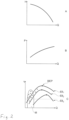
- the electronic control 6 has a further function with which the operating points are recorded at intervals of three minutes during operation of the pump unit and these are evaluated with regard to their energy efficiency, as can be seen from the Fig. 2A to C as explained below:
- the Fig. 2A shows a typical pump curve of a pump unit, where the delivery head is plotted as a function of the delivery rate.
- the delivery head is the differential pressure between the pump inlet and pump outlet, the delivery rate is the volume flow per unit of time.
- the Fig. 2A The schematically shown pump curve represents a centrifugal pump at a constant speed.
- the Fig. 2B shows the electrical power P of this pump unit as a function of the flow rate.
- the pump unit can be operated on a variety of different pump curves according to Fig. 2A and 2B driven, as shown by Fig. 2C , which shows three such curves ⁇ 1, ⁇ 2 and ⁇ 3, which represent different speeds.
- These curves represent the efficiency ⁇ as a function of the flow rate at a speed.
- the efficiency is the quotient of hydraulic power and electrical power, ideally one.
- the electrical power is determined by the input power, i.e. the product of current and voltage of the driving electric motor or motors, and is available in the form of data in the control unit 6.
- the hydraulic power results from the product of flow rate, discharge head, density and gravitational acceleration. It can be calculated using differential pressure and flow sensors.
- the electronic control system checks the efficiency at the pump's operating points using the previously determined effectiveness curves, which are either determined during operation or are specifically approached. of the operating points under temporal correlation, whether they are in the range of the BEP's or outside.
- a limit value of 30%, for example, is used as a basis, so that only the number of operating points outside this 30% limit and how many are within it is considered. The points outside this limit are in Fig. 2C shown in group M.
- the electronic control 6 is thus able to check whether the pump unit can be operated in a more energy-efficient range by changing the setting parameters. If this is the case, the control 6 sends a corresponding signal to the network so that the manufacturer or operator is prompted to change the setting parameters.
- the setting parameters suitable for the pump unit can be specified by the manufacturer and transmitted wirelessly via the network to the smartphone 9 of the operator 10, who then transmits them to the electronic control 6 of the pump unit 1, or they can be selected and set by the operator himself.
- Fig. 2C the operating points are shown in a range M that lies outside the 30% of the BEPs. It is therefore shown that eight of the ten operating points lie outside the 30% range and thus 80% of the operating points fall below the specified efficiency limit range. In this case, an adjustment of the setting parameters is required.
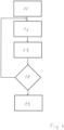
- a first step 15 the efficiency curves of the pump unit are generated. These can either be targeted or during operation for different flow rates in Dependence on the speed, which is always known on the motor side and therefore on the control side. Since the curves are never complete, the pump unit must either be controlled to run the complete curve or interpolated. In practice, it is sufficient to determine the BEPs that result for each speed. Once this data has been collected, the efficiency test of the pump can be carried out during operation. It goes without saying that these procedures can initially overlap in time, but this is not a problem.
- the efficiency monitoring is to be run again after a time interval of, for example, six months or one or two years after the pump has been put into operation and the first check, it starts in step 16 after the timer has expired according to the set time of six months, one or two years after the first check of the pump unit.
- the efficiency of the current operating point of the pump unit is now calculated and saved at a predetermined time interval, for example ten minutes. After a predetermined time of, for example, 48 hours, this calculation and saving of the efficiency in the operating points is terminated in the third step 17.
- the distribution of the operating points is then evaluated on the control side with regard to their efficiency in relation to the BEP. If a predetermined percentage of the operating points, for example more than 60% of the operating points, fall below the BEP by more than 30%, a signal is emitted in the fifth step 19, depending on the evaluation result, to change the setting parameters or to replace the pump with a smaller or larger one.
- the process may only be restarted after a predetermined time interval has elapsed, so that the pump unit is monitored for efficiency over its entire operating period. If the setting parameters are changed after the signal is sent in the fifth step 19, the process is also resumed in the second step 16, whereas if the pump is replaced, the process starts again with the first step 15.
Landscapes
- Engineering & Computer Science (AREA)
- Mechanical Engineering (AREA)
- General Engineering & Computer Science (AREA)
- Control Of Non-Positive-Displacement Pumps (AREA)
- Control Of Positive-Displacement Pumps (AREA)
Claims (11)
- Procédé destiné à faire fonctionner un ensemble de pompe centrifuge à commande électronique, pour lequel des paramètres de réglage de la pompe peuvent être réglés dans une commande électronique pour adaptation aux exigences hydrauliques de la situation de mise en oeuvre locale et pour lequel des données de fonctionnement de l'ensemble de pompe sont enregistrées pendant le fonctionnement, caractérisé en ce qu'après un temps prédéterminé, il est vérifié après enregistrement du fonctionnement de l'ensemble de pompe centrifuge (1), si tous les paramètres de réglage n'ont pas été modifiés par rapport à une configuration usine, sachant que les paramètres de réglage sont numériquement mémorisés dans un fichier de la commande (6) et la commande (6) surveille les données mémorisées du fichier et une minuterie est prévue, qui fonctionne depuis la première mise en service pour le temps prédéterminé et après expiration de ce temps prédéterminé, il est vérifié si les données mémorisées du fichier se sont modifiées ou non et en ce qu'ensuite, si une modification des données mémorisées du fichier n'est pas constatée, un signal est délivré pour modifier les paramètres de réglage.
- Procédé selon la revendication 1, caractérisé en ce que l'enregistrement des données de fonctionnement et le contrôle au bout du temps prédéterminé ou d'un intervalle de temps sont répétés après contrôle effectué.
- Procédé selon la revendication 1 ou 2, caractérisé en ce qu'après le temps prédéterminé, il est en plus vérifié à l'aide des données de fonctionnement enregistrées, si une ou plusieurs valeurs limites de données de fonctionnement prédéterminées de préférence en corrélation avec le temps ont été dépassées et, ensuite, si cela est constaté, un signal est délivré pour modifier les paramètres de réglage.
- Procédé selon l'une quelconque des revendications précédentes, caractérisé en ce que les données de fonctionnement de l'ensemble de pompe sont enregistrées par un réseau basé sur Internet et après le temps prédéterminé il est vérifié côté réseau, si l'ensemble de pompe peut être utilisé dans une plage énergétiquement plus favorable pour adapter ou maintenir ensuite en conséquence de préférence côté réseau les paramètres de réglage ou conditionner les paramètres de réglage pour prise en charge.
- Procédé selon l'une quelconque des revendications précédentes, caractérisé en ce que le temps prédéterminé se situe entre une heure et sept jours et/ou comporte l'intervalle de temps entre 1 à 5 ans.
- Procédé selon l'une quelconque des revendications précédentes, caractérisé en ce que le signal active un affichage optique et/ou un signal acoustique ou est transmis par le réseau à base Internet de préférence en même temps que les données normalisées de l'ensemble de pompe.
- Commande électronique (6) d'un ensemble de pompe centrifuge entraîné par moteur électrique (1) pour exécuter le procédé selon l'une quelconque des revendications précédentes, avec des moyens de réglage des paramètres de réglage pour l'adaptation de l'ensemble de pompe (1) aux exigences hydrauliques de la situation de mise en oeuvre locale (4,5), sachant que la commande (6) est constituée pour enregistrer et/ou transmettre des données de fonctionnement, caractérisée en ce que la commande (6) est en plus constituée pour déterminer, si un réglage des paramètres de réglage a été modifié au bout d'un temps prédéterminé par rapport à la configuration usine et en cas de modification non effectuée délivrer automatiquement un signal, sachant que les paramètres de réglage sont numériquement mémorisés dans un fichier de la commande (6) et la commande (6) surveille les données mémorisées du fichier et qu'une minuterie est prévue, laquelle se met en marche dès la première mise en service de telle sorte qu'après expiration de ce temps prédéterminé, il est vérifié si les données mémorisées du fichier se sont modifiées ou non et émettre le signal en cas d'une modification.
- Commande électronique selon la revendication 7, caractérisée en ce que la commande (6) comporte une interface vers un réseau (8) de préférence basé sur Internet par lequel le signal et/ou les données de fonctionnement peuvent être transmis.
- Commande électronique selon la revendication 7 ou 8, caractérisée en ce que la commande (6) comporte une interface pour la transmission de données sans fil.
- Commande électronique selon la revendication 9, caractérisée en ce que la commande (6) est constituée pour la transmission sans fil des paramètres de réglage au moyen d'une application logicielle d'un appareil d'introduction mobile, en particulier d'un téléphone multifonctions (9) et/ou pour la transmission à partir d'un réseau (8).
- Commande électronique selon l'une quelconque des revendications 7-10, caractérisée en ce que les paramètres de réglage sont une ou plusieurs valeurs de réglag: débit, pression de refoulement, vitesse de rotation, puissance, sachant que le débit et/ou la pression de refoulement peuvent être réglés sous la forme de courbes de réglage.
Priority Applications (8)
| Application Number | Priority Date | Filing Date | Title |
|---|---|---|---|
| EP16207574.1A EP3242033B1 (fr) | 2016-12-30 | 2016-12-30 | Procédé de fonctionnement d'un groupe motopompe à commande électrique |
| EP24165496.1A EP4365453A3 (fr) | 2016-12-30 | 2016-12-30 | Procédé de fonctionnement d'un groupe motopompe à commande électronique |
| ES16207574T ES2982439T3 (es) | 2016-12-30 | 2016-12-30 | Método para operar una unidad de bomba controlada electrónicamente |
| PCT/EP2017/083381 WO2018122025A1 (fr) | 2016-12-30 | 2017-12-18 | Procédé servant à faire fonctionner un groupe motopompe à commande électronique |
| CN202111037201.5A CN113757132A (zh) | 2016-12-30 | 2017-12-18 | 用于运行电子控制的泵机组的方法 |
| CN201780081740.4A CN110139990B (zh) | 2016-12-30 | 2017-12-18 | 用于运行电子控制的泵机组的方法 |
| US16/474,929 US11566625B2 (en) | 2016-12-30 | 2017-12-18 | Method for operating an electronically controlled pump assembly |
| US18/086,867 US11933307B2 (en) | 2016-12-30 | 2022-12-22 | Method for operating an electronically controlled pump assembly |
Applications Claiming Priority (1)
| Application Number | Priority Date | Filing Date | Title |
|---|---|---|---|
| EP16207574.1A EP3242033B1 (fr) | 2016-12-30 | 2016-12-30 | Procédé de fonctionnement d'un groupe motopompe à commande électrique |
Related Child Applications (2)
| Application Number | Title | Priority Date | Filing Date |
|---|---|---|---|
| EP24165496.1A Division EP4365453A3 (fr) | 2016-12-30 | 2016-12-30 | Procédé de fonctionnement d'un groupe motopompe à commande électronique |
| EP24165496.1A Division-Into EP4365453A3 (fr) | 2016-12-30 | 2016-12-30 | Procédé de fonctionnement d'un groupe motopompe à commande électronique |
Publications (3)
| Publication Number | Publication Date |
|---|---|
| EP3242033A1 EP3242033A1 (fr) | 2017-11-08 |
| EP3242033B1 true EP3242033B1 (fr) | 2024-05-01 |
| EP3242033C0 EP3242033C0 (fr) | 2024-05-01 |
Family
ID=57680165
Family Applications (2)
| Application Number | Title | Priority Date | Filing Date |
|---|---|---|---|
| EP24165496.1A Pending EP4365453A3 (fr) | 2016-12-30 | 2016-12-30 | Procédé de fonctionnement d'un groupe motopompe à commande électronique |
| EP16207574.1A Active EP3242033B1 (fr) | 2016-12-30 | 2016-12-30 | Procédé de fonctionnement d'un groupe motopompe à commande électrique |
Family Applications Before (1)
| Application Number | Title | Priority Date | Filing Date |
|---|---|---|---|
| EP24165496.1A Pending EP4365453A3 (fr) | 2016-12-30 | 2016-12-30 | Procédé de fonctionnement d'un groupe motopompe à commande électronique |
Country Status (5)
| Country | Link |
|---|---|
| US (2) | US11566625B2 (fr) |
| EP (2) | EP4365453A3 (fr) |
| CN (2) | CN110139990B (fr) |
| ES (1) | ES2982439T3 (fr) |
| WO (1) | WO2018122025A1 (fr) |
Families Citing this family (7)
| Publication number | Priority date | Publication date | Assignee | Title |
|---|---|---|---|---|
| EP3483449B1 (fr) * | 2017-11-13 | 2023-11-08 | Wilo Se | Procédé de surveillance d'une pompe centrifuge à régulation électronique |
| EP3710897B1 (fr) * | 2017-11-15 | 2022-08-03 | KSB SE & Co. KGaA | Procédé et dispositif de protection contre des cyberattaques de groupes motopompes |
| IT201800003117A1 (it) * | 2018-02-28 | 2019-08-28 | Dab Pumps Spa | Assemblato di elettropompa centrifuga con dispositivo migliorato di interfaccia utente |
| CN110939560B (zh) | 2019-11-04 | 2021-09-14 | 姚福来 | 水泵机组节电寻优运行和切换点确定方法 |
| US11441973B2 (en) | 2020-02-21 | 2022-09-13 | Hamilton Sundstrand Corporation | Pump health monitoring |
| US20230407863A1 (en) * | 2022-06-21 | 2023-12-21 | Viking Pump, Inc. | Pump monitoring system and method |
| CN120712415A (zh) * | 2023-02-15 | 2025-09-26 | 格兰富控股公司 | 一种用于自动确定已安装泵系统的运行曲线的方法 |
Family Cites Families (27)
| Publication number | Priority date | Publication date | Assignee | Title |
|---|---|---|---|---|
| DE19618462A1 (de) * | 1996-05-08 | 1997-11-13 | Status Pro Maschinenmesstechni | Verfahren und Vorrichtung zum Bestimmen eines extrinsischen Leistungsparameters einer energieumwandelnden Vorrichtung |
| US6260004B1 (en) * | 1997-12-31 | 2001-07-10 | Innovation Management Group, Inc. | Method and apparatus for diagnosing a pump system |
| US6655922B1 (en) * | 2001-08-10 | 2003-12-02 | Rockwell Automation Technologies, Inc. | System and method for detecting and diagnosing pump cavitation |
| CN100362448C (zh) * | 2003-02-26 | 2008-01-16 | 华为技术有限公司 | 一种监控风扇运行的方法 |
| US7634328B2 (en) * | 2004-01-20 | 2009-12-15 | Masoud Medizade | Method, system and computer program product for monitoring and optimizing fluid extraction from geologic strata |
| DE502004006565D1 (de) * | 2004-02-11 | 2008-04-30 | Grundfos As | Verfahren zur Ermittlung von Fehlern beim Betrieb eines Pumpenaggregates |
| EP1614903B1 (fr) * | 2004-07-07 | 2019-05-22 | Grundfos A/S | Unité moteur pour entrainer une pompe centrifuge |
| US7854597B2 (en) * | 2004-08-26 | 2010-12-21 | Pentair Water Pool And Spa, Inc. | Pumping system with two way communication |
| US7686589B2 (en) * | 2004-08-26 | 2010-03-30 | Pentair Water Pool And Spa, Inc. | Pumping system with power optimization |
| DE102005006410A1 (de) * | 2005-02-11 | 2006-08-17 | Siemens Ag | Verfahren zur Optimierung des Betriebs mehrerer Verdichteraggregate und Vorrichtung hierzu |
| EP2039939B2 (fr) * | 2007-09-20 | 2020-11-18 | Grundfos Management A/S | Procédé de surveillance d'un dispositif de transformation d'énergie |
| DE102009022107A1 (de) * | 2009-05-20 | 2010-11-25 | Ksb Ag | Verfahren und Vorrichtung zur Betriebspunktbestimmung einer Arbeitsmaschine |
| US9181953B2 (en) * | 2009-10-01 | 2015-11-10 | Specific Energy | Controlling pumps for improved energy efficiency |
| US9341178B1 (en) * | 2010-07-26 | 2016-05-17 | Lincoln Williams | Energy optimization for variable speed pumps |
| KR20120132776A (ko) * | 2011-05-30 | 2012-12-10 | 주식회사 협성히스코 | 열역학적 펌프효율측정을 이용한 펌프 스케줄링 방법 및 그 시스템 |
| EP2573403B1 (fr) * | 2011-09-20 | 2017-12-06 | Grundfos Holding A/S | Pompe |
| WO2013075113A1 (fr) * | 2011-11-18 | 2013-05-23 | Cooper Technologies, Inc. | Rendement amélioré de chauffage, de ventilation et de climatisation par extension indirecte de temps de fonctionnement de compresseur |
| DE102011120686A1 (de) * | 2011-12-09 | 2013-06-13 | Daimler Ag | Verfahren zum Überwachen einer Pumpe |
| US20130204546A1 (en) * | 2012-02-02 | 2013-08-08 | Ghd Pty Ltd. | On-line pump efficiency determining system and related method for determining pump efficiency |
| KR101311715B1 (ko) * | 2012-06-22 | 2013-09-25 | 한국농어촌공사 | 소규모 급수 시스템 및 이의 제어 방법 |
| US20150122037A1 (en) * | 2013-10-30 | 2015-05-07 | Syncrude Canada Ltd. In Trust For The Owners Of The Syncrude Project | Method for diagnosing faults in slurry pump impellers |
| US10947982B2 (en) * | 2014-02-06 | 2021-03-16 | Hyundai Motor Company | Method of determining circulation state of cooling water |
| DE102014018020A1 (de) * | 2014-12-08 | 2016-06-09 | Wilo Se | Verfahren zum Betreiben einer Kreiselpumpe |
| DE102014226620A1 (de) * | 2014-12-19 | 2016-06-23 | Robert Bosch Gmbh | Verfahren und Vorrichtung zur Parametrierung zumindest einer Komponente einer elektrohydraulischen Antriebseinheit |
| RU2721446C2 (ru) * | 2015-07-24 | 2020-05-19 | Флюид Хэндлинг ЭлЭлСи | Усовершенствованная система графического бессенсорного энергосберегающего управления насосами в режиме реального времени |
| KR101846625B1 (ko) * | 2015-10-23 | 2018-04-09 | 현대자동차주식회사 | 냉각수 상태 진단 시스템 및 방법 |
| US10208745B2 (en) * | 2015-12-18 | 2019-02-19 | General Electric Company | System and method for controlling a fluid transport system |
-
2016
- 2016-12-30 EP EP24165496.1A patent/EP4365453A3/fr active Pending
- 2016-12-30 EP EP16207574.1A patent/EP3242033B1/fr active Active
- 2016-12-30 ES ES16207574T patent/ES2982439T3/es active Active
-
2017
- 2017-12-18 CN CN201780081740.4A patent/CN110139990B/zh active Active
- 2017-12-18 US US16/474,929 patent/US11566625B2/en active Active
- 2017-12-18 WO PCT/EP2017/083381 patent/WO2018122025A1/fr not_active Ceased
- 2017-12-18 CN CN202111037201.5A patent/CN113757132A/zh active Pending
-
2022
- 2022-12-22 US US18/086,867 patent/US11933307B2/en active Active
Also Published As
| Publication number | Publication date |
|---|---|
| CN113757132A (zh) | 2021-12-07 |
| US11566625B2 (en) | 2023-01-31 |
| EP4365453A2 (fr) | 2024-05-08 |
| EP3242033A1 (fr) | 2017-11-08 |
| US20190323494A1 (en) | 2019-10-24 |
| ES2982439T3 (es) | 2024-10-16 |
| EP3242033C0 (fr) | 2024-05-01 |
| US20230129537A1 (en) | 2023-04-27 |
| WO2018122025A1 (fr) | 2018-07-05 |
| EP4365453A3 (fr) | 2024-07-10 |
| US11933307B2 (en) | 2024-03-19 |
| CN110139990B (zh) | 2021-09-28 |
| CN110139990A (zh) | 2019-08-16 |
Similar Documents
| Publication | Publication Date | Title |
|---|---|---|
| EP3242033B1 (fr) | Procédé de fonctionnement d'un groupe motopompe à commande électrique | |
| EP2258949B1 (fr) | Procédé de détermination de valeurs caractéristiques, notamment de valeurs, notamment de paramètres, d'un agrégat de pompe centrifuge entraîné par moteur électrique intégré dans une installation | |
| EP2913526B1 (fr) | Procédé de transport de fluide hydraulique et unité de pompe/moteur électrohydraulique associée | |
| EP2354555B1 (fr) | Procédé d'optimisation de l'énergie de pompes | |
| DE102007010768B4 (de) | Verfahren für die Optimierung der Ventilstellung und der Pumpendrehzahl in einem Ventilsystem mit PID-Regelung ohne die Verwendung externer Signale | |
| DE102011119299A1 (de) | Verfahren zum Betreiben einerdrehzahlvariablen Verstellpumpe | |
| EP3242035A1 (fr) | Procédé de fonctionnement d'au moins un groupe motopompe parmi une pluralité de groupes motopompe | |
| EP3910215A1 (fr) | Agencement hydraulique pour une transmission de véhicule | |
| DE102014222962A1 (de) | Effizienter Betrieb von Mehrpumpenanlagen | |
| EP3655663A1 (fr) | Procédé de réglage d'au moins deux ventilateurs | |
| EP2831345A1 (fr) | Procédé pour commander un groupe pompe | |
| DE102015117917A1 (de) | System mit schlupffähiger Drehmomentübertragungseinrichtung, die eine Kraftmaschinenkurbelwelle und eine kraftmaschinengetriebene Komponente verbindet, sowie Fahrzeug | |
| EP3874338B1 (fr) | Procédé de fonctionnement d'une soupape, unité de commande électronique associée et entraînement de soupape | |
| EP3164308B1 (fr) | Agencement de commande d'un équipement de véhicules automobile respectivement et procédé de fonctionnement correspondant | |
| EP2923837A1 (fr) | Procédé de réduction de la charge de pointe dans une presse | |
| DE102013200389A1 (de) | Verfahren zum Einstellen eines Systemdrucks, sowie Kraftfahrzeuggetriebe | |
| DE102011051540A1 (de) | Fahrzeugtemperierungsvorrichtung | |
| DE102021208820A1 (de) | Verfahren zum geräuscharmen Betrieb eines elektrisch angetriebenen Hydrauliksystems | |
| EP3483449B1 (fr) | Procédé de surveillance d'une pompe centrifuge à régulation électronique | |
| EP3710897B1 (fr) | Procédé et dispositif de protection contre des cyberattaques de groupes motopompes | |
| EP4524400A1 (fr) | Procede et dispositif de commande d'un dispositif de production d'ecoulement | |
| EP3808977A2 (fr) | Système hydraulique | |
| DE102017125307B4 (de) | Zentralschmieranlage und System | |
| EP4189295B1 (fr) | Procédé de contrôle d'une pompe de circulation, en particulier d'une pompe de chauffage | |
| EP2984240B1 (fr) | Procédé pour faire fonctionner un ensemble de damage par vibrations |
Legal Events
| Date | Code | Title | Description |
|---|---|---|---|
| PUAI | Public reference made under article 153(3) epc to a published international application that has entered the european phase |
Free format text: ORIGINAL CODE: 0009012 |
|
| STAA | Information on the status of an ep patent application or granted ep patent |
Free format text: STATUS: THE APPLICATION HAS BEEN PUBLISHED |
|
| AK | Designated contracting states |
Kind code of ref document: A1 Designated state(s): AL AT BE BG CH CY CZ DE DK EE ES FI FR GB GR HR HU IE IS IT LI LT LU LV MC MK MT NL NO PL PT RO RS SE SI SK SM TR |
|
| AX | Request for extension of the european patent |
Extension state: BA ME |
|
| STAA | Information on the status of an ep patent application or granted ep patent |
Free format text: STATUS: REQUEST FOR EXAMINATION WAS MADE |
|
| 17P | Request for examination filed |
Effective date: 20180508 |
|
| RBV | Designated contracting states (corrected) |
Designated state(s): AL AT BE BG CH CY CZ DE DK EE ES FI FR GB GR HR HU IE IS IT LI LT LU LV MC MK MT NL NO PL PT RO RS SE SI SK SM TR |
|
| STAA | Information on the status of an ep patent application or granted ep patent |
Free format text: STATUS: EXAMINATION IS IN PROGRESS |
|
| 17Q | First examination report despatched |
Effective date: 20200414 |
|
| GRAP | Despatch of communication of intention to grant a patent |
Free format text: ORIGINAL CODE: EPIDOSNIGR1 |
|
| STAA | Information on the status of an ep patent application or granted ep patent |
Free format text: STATUS: GRANT OF PATENT IS INTENDED |
|
| INTG | Intention to grant announced |
Effective date: 20231213 |
|
| GRAS | Grant fee paid |
Free format text: ORIGINAL CODE: EPIDOSNIGR3 |
|
| GRAA | (expected) grant |
Free format text: ORIGINAL CODE: 0009210 |
|
| STAA | Information on the status of an ep patent application or granted ep patent |
Free format text: STATUS: THE PATENT HAS BEEN GRANTED |
|
| AK | Designated contracting states |
Kind code of ref document: B1 Designated state(s): AL AT BE BG CH CY CZ DE DK EE ES FI FR GB GR HR HU IE IS IT LI LT LU LV MC MK MT NL NO PL PT RO RS SE SI SK SM TR |
|
| REG | Reference to a national code |
Ref country code: GB Ref legal event code: FG4D Free format text: NOT ENGLISH |
|
| REG | Reference to a national code |
Ref country code: CH Ref legal event code: EP |
|
| REG | Reference to a national code |
Ref country code: IE Ref legal event code: FG4D Free format text: LANGUAGE OF EP DOCUMENT: GERMAN |
|
| REG | Reference to a national code |
Ref country code: DE Ref legal event code: R096 Ref document number: 502016016498 Country of ref document: DE |
|
| U01 | Request for unitary effect filed |
Effective date: 20240529 |
|
| U07 | Unitary effect registered |
Designated state(s): AT BE BG DE DK EE FI FR IT LT LU LV MT NL PT SE SI Effective date: 20240607 |
|
| PG25 | Lapsed in a contracting state [announced via postgrant information from national office to epo] |
Ref country code: IS Free format text: LAPSE BECAUSE OF FAILURE TO SUBMIT A TRANSLATION OF THE DESCRIPTION OR TO PAY THE FEE WITHIN THE PRESCRIBED TIME-LIMIT Effective date: 20240901 |
|
| PG25 | Lapsed in a contracting state [announced via postgrant information from national office to epo] |
Ref country code: HR Free format text: LAPSE BECAUSE OF FAILURE TO SUBMIT A TRANSLATION OF THE DESCRIPTION OR TO PAY THE FEE WITHIN THE PRESCRIBED TIME-LIMIT Effective date: 20240501 |
|
| PG25 | Lapsed in a contracting state [announced via postgrant information from national office to epo] |
Ref country code: GR Free format text: LAPSE BECAUSE OF FAILURE TO SUBMIT A TRANSLATION OF THE DESCRIPTION OR TO PAY THE FEE WITHIN THE PRESCRIBED TIME-LIMIT Effective date: 20240802 |
|
| REG | Reference to a national code |
Ref country code: ES Ref legal event code: FG2A Ref document number: 2982439 Country of ref document: ES Kind code of ref document: T3 Effective date: 20241016 |
|
| PG25 | Lapsed in a contracting state [announced via postgrant information from national office to epo] |
Ref country code: PL Free format text: LAPSE BECAUSE OF FAILURE TO SUBMIT A TRANSLATION OF THE DESCRIPTION OR TO PAY THE FEE WITHIN THE PRESCRIBED TIME-LIMIT Effective date: 20240501 |
|
| PG25 | Lapsed in a contracting state [announced via postgrant information from national office to epo] |
Ref country code: PL Free format text: LAPSE BECAUSE OF FAILURE TO SUBMIT A TRANSLATION OF THE DESCRIPTION OR TO PAY THE FEE WITHIN THE PRESCRIBED TIME-LIMIT Effective date: 20240501 Ref country code: NO Free format text: LAPSE BECAUSE OF FAILURE TO SUBMIT A TRANSLATION OF THE DESCRIPTION OR TO PAY THE FEE WITHIN THE PRESCRIBED TIME-LIMIT Effective date: 20240801 Ref country code: IS Free format text: LAPSE BECAUSE OF FAILURE TO SUBMIT A TRANSLATION OF THE DESCRIPTION OR TO PAY THE FEE WITHIN THE PRESCRIBED TIME-LIMIT Effective date: 20240901 Ref country code: HR Free format text: LAPSE BECAUSE OF FAILURE TO SUBMIT A TRANSLATION OF THE DESCRIPTION OR TO PAY THE FEE WITHIN THE PRESCRIBED TIME-LIMIT Effective date: 20240501 Ref country code: GR Free format text: LAPSE BECAUSE OF FAILURE TO SUBMIT A TRANSLATION OF THE DESCRIPTION OR TO PAY THE FEE WITHIN THE PRESCRIBED TIME-LIMIT Effective date: 20240802 Ref country code: RS Free format text: LAPSE BECAUSE OF FAILURE TO SUBMIT A TRANSLATION OF THE DESCRIPTION OR TO PAY THE FEE WITHIN THE PRESCRIBED TIME-LIMIT Effective date: 20240801 |
|
| PG25 | Lapsed in a contracting state [announced via postgrant information from national office to epo] |
Ref country code: CZ Free format text: LAPSE BECAUSE OF FAILURE TO SUBMIT A TRANSLATION OF THE DESCRIPTION OR TO PAY THE FEE WITHIN THE PRESCRIBED TIME-LIMIT Effective date: 20240501 |
|
| PG25 | Lapsed in a contracting state [announced via postgrant information from national office to epo] |
Ref country code: SK Free format text: LAPSE BECAUSE OF FAILURE TO SUBMIT A TRANSLATION OF THE DESCRIPTION OR TO PAY THE FEE WITHIN THE PRESCRIBED TIME-LIMIT Effective date: 20240501 Ref country code: RO Free format text: LAPSE BECAUSE OF FAILURE TO SUBMIT A TRANSLATION OF THE DESCRIPTION OR TO PAY THE FEE WITHIN THE PRESCRIBED TIME-LIMIT Effective date: 20240501 |
|
| PG25 | Lapsed in a contracting state [announced via postgrant information from national office to epo] |
Ref country code: SM Free format text: LAPSE BECAUSE OF FAILURE TO SUBMIT A TRANSLATION OF THE DESCRIPTION OR TO PAY THE FEE WITHIN THE PRESCRIBED TIME-LIMIT Effective date: 20240501 |
|
| PG25 | Lapsed in a contracting state [announced via postgrant information from national office to epo] |
Ref country code: SM Free format text: LAPSE BECAUSE OF FAILURE TO SUBMIT A TRANSLATION OF THE DESCRIPTION OR TO PAY THE FEE WITHIN THE PRESCRIBED TIME-LIMIT Effective date: 20240501 Ref country code: SK Free format text: LAPSE BECAUSE OF FAILURE TO SUBMIT A TRANSLATION OF THE DESCRIPTION OR TO PAY THE FEE WITHIN THE PRESCRIBED TIME-LIMIT Effective date: 20240501 Ref country code: RO Free format text: LAPSE BECAUSE OF FAILURE TO SUBMIT A TRANSLATION OF THE DESCRIPTION OR TO PAY THE FEE WITHIN THE PRESCRIBED TIME-LIMIT Effective date: 20240501 Ref country code: CZ Free format text: LAPSE BECAUSE OF FAILURE TO SUBMIT A TRANSLATION OF THE DESCRIPTION OR TO PAY THE FEE WITHIN THE PRESCRIBED TIME-LIMIT Effective date: 20240501 |
|
| REG | Reference to a national code |
Ref country code: DE Ref legal event code: R097 Ref document number: 502016016498 Country of ref document: DE |
|
| U20 | Renewal fee for the european patent with unitary effect paid |
Year of fee payment: 9 Effective date: 20241227 |
|
| PLBE | No opposition filed within time limit |
Free format text: ORIGINAL CODE: 0009261 |
|
| STAA | Information on the status of an ep patent application or granted ep patent |
Free format text: STATUS: NO OPPOSITION FILED WITHIN TIME LIMIT |
|
| 26N | No opposition filed |
Effective date: 20250204 |
|
| PG25 | Lapsed in a contracting state [announced via postgrant information from national office to epo] |
Ref country code: MC Free format text: LAPSE BECAUSE OF FAILURE TO SUBMIT A TRANSLATION OF THE DESCRIPTION OR TO PAY THE FEE WITHIN THE PRESCRIBED TIME-LIMIT Effective date: 20240501 |
|
| REG | Reference to a national code |
Ref country code: CH Ref legal event code: PL |
|
| PG25 | Lapsed in a contracting state [announced via postgrant information from national office to epo] |
Ref country code: CH Free format text: LAPSE BECAUSE OF NON-PAYMENT OF DUE FEES Effective date: 20241231 |
|
| PG25 | Lapsed in a contracting state [announced via postgrant information from national office to epo] |
Ref country code: IE Free format text: LAPSE BECAUSE OF NON-PAYMENT OF DUE FEES Effective date: 20241230 |
|
| PGFP | Annual fee paid to national office [announced via postgrant information from national office to epo] |
Ref country code: GB Payment date: 20251219 Year of fee payment: 10 |
|
| U20 | Renewal fee for the european patent with unitary effect paid |
Year of fee payment: 10 Effective date: 20251230 |
|
| PGFP | Annual fee paid to national office [announced via postgrant information from national office to epo] |
Ref country code: ES Payment date: 20260130 Year of fee payment: 10 |