EP4524400A1 - Procede et dispositif de commande d'un dispositif de production d'ecoulement - Google Patents
Procede et dispositif de commande d'un dispositif de production d'ecoulement Download PDFInfo
- Publication number
- EP4524400A1 EP4524400A1 EP24198654.6A EP24198654A EP4524400A1 EP 4524400 A1 EP4524400 A1 EP 4524400A1 EP 24198654 A EP24198654 A EP 24198654A EP 4524400 A1 EP4524400 A1 EP 4524400A1
- Authority
- EP
- European Patent Office
- Prior art keywords
- parameter
- flow
- sensor
- control
- relationship
- Prior art date
- Legal status (The legal status is an assumption and is not a legal conclusion. Google has not performed a legal analysis and makes no representation as to the accuracy of the status listed.)
- Granted
Links
Images
Classifications
-
- F—MECHANICAL ENGINEERING; LIGHTING; HEATING; WEAPONS; BLASTING
- F04—POSITIVE - DISPLACEMENT MACHINES FOR LIQUIDS; PUMPS FOR LIQUIDS OR ELASTIC FLUIDS
- F04B—POSITIVE-DISPLACEMENT MACHINES FOR LIQUIDS; PUMPS
- F04B49/00—Control, e.g. of pump delivery, or pump pressure of, or safety measures for, machines, pumps, or pumping installations, not otherwise provided for, or of interest apart from, groups F04B1/00 - F04B47/00
- F04B49/06—Control using electricity
- F04B49/065—Control using electricity and making use of computers
-
- F—MECHANICAL ENGINEERING; LIGHTING; HEATING; WEAPONS; BLASTING
- F04—POSITIVE - DISPLACEMENT MACHINES FOR LIQUIDS; PUMPS FOR LIQUIDS OR ELASTIC FLUIDS
- F04B—POSITIVE-DISPLACEMENT MACHINES FOR LIQUIDS; PUMPS
- F04B51/00—Testing machines, pumps, or pumping installations
-
- F—MECHANICAL ENGINEERING; LIGHTING; HEATING; WEAPONS; BLASTING
- F04—POSITIVE - DISPLACEMENT MACHINES FOR LIQUIDS; PUMPS FOR LIQUIDS OR ELASTIC FLUIDS
- F04D—NON-POSITIVE-DISPLACEMENT PUMPS
- F04D15/00—Control, e.g. regulation, of pumps, pumping installations or systems
-
- F—MECHANICAL ENGINEERING; LIGHTING; HEATING; WEAPONS; BLASTING
- F04—POSITIVE - DISPLACEMENT MACHINES FOR LIQUIDS; PUMPS FOR LIQUIDS OR ELASTIC FLUIDS
- F04D—NON-POSITIVE-DISPLACEMENT PUMPS
- F04D15/00—Control, e.g. regulation, of pumps, pumping installations or systems
- F04D15/0066—Control, e.g. regulation, of pumps, pumping installations or systems by changing the speed, e.g. of the driving engine
-
- F—MECHANICAL ENGINEERING; LIGHTING; HEATING; WEAPONS; BLASTING
- F04—POSITIVE - DISPLACEMENT MACHINES FOR LIQUIDS; PUMPS FOR LIQUIDS OR ELASTIC FLUIDS
- F04D—NON-POSITIVE-DISPLACEMENT PUMPS
- F04D15/00—Control, e.g. regulation, of pumps, pumping installations or systems
- F04D15/0088—Testing machines
-
- F—MECHANICAL ENGINEERING; LIGHTING; HEATING; WEAPONS; BLASTING
- F04—POSITIVE - DISPLACEMENT MACHINES FOR LIQUIDS; PUMPS FOR LIQUIDS OR ELASTIC FLUIDS
- F04D—NON-POSITIVE-DISPLACEMENT PUMPS
- F04D27/00—Control, e.g. regulation, of pumps, pumping installations or pumping systems specially adapted for elastic fluids
- F04D27/001—Testing thereof; Determination or simulation of flow characteristics; Stall or surge detection, e.g. condition monitoring
-
- F—MECHANICAL ENGINEERING; LIGHTING; HEATING; WEAPONS; BLASTING
- F04—POSITIVE - DISPLACEMENT MACHINES FOR LIQUIDS; PUMPS FOR LIQUIDS OR ELASTIC FLUIDS
- F04D—NON-POSITIVE-DISPLACEMENT PUMPS
- F04D27/00—Control, e.g. regulation, of pumps, pumping installations or pumping systems specially adapted for elastic fluids
- F04D27/004—Control, e.g. regulation, of pumps, pumping installations or pumping systems specially adapted for elastic fluids by varying driving speed
-
- F—MECHANICAL ENGINEERING; LIGHTING; HEATING; WEAPONS; BLASTING
- F04—POSITIVE - DISPLACEMENT MACHINES FOR LIQUIDS; PUMPS FOR LIQUIDS OR ELASTIC FLUIDS
- F04D—NON-POSITIVE-DISPLACEMENT PUMPS
- F04D27/00—Control, e.g. regulation, of pumps, pumping installations or pumping systems specially adapted for elastic fluids
- F04D27/02—Surge control
- F04D27/0261—Surge control by varying driving speed
-
- G—PHYSICS
- G06—COMPUTING OR CALCULATING; COUNTING
- G06N—COMPUTING ARRANGEMENTS BASED ON SPECIFIC COMPUTATIONAL MODELS
- G06N20/00—Machine learning
-
- F—MECHANICAL ENGINEERING; LIGHTING; HEATING; WEAPONS; BLASTING
- F04—POSITIVE - DISPLACEMENT MACHINES FOR LIQUIDS; PUMPS FOR LIQUIDS OR ELASTIC FLUIDS
- F04B—POSITIVE-DISPLACEMENT MACHINES FOR LIQUIDS; PUMPS
- F04B2203/00—Motor parameters
- F04B2203/02—Motor parameters of rotating electric motors
- F04B2203/0206—Vibration
-
- F—MECHANICAL ENGINEERING; LIGHTING; HEATING; WEAPONS; BLASTING
- F05—INDEXING SCHEMES RELATING TO ENGINES OR PUMPS IN VARIOUS SUBCLASSES OF CLASSES F01-F04
- F05D—INDEXING SCHEME FOR ASPECTS RELATING TO NON-POSITIVE-DISPLACEMENT MACHINES OR ENGINES, GAS-TURBINES OR JET-PROPULSION PLANTS
- F05D2260/00—Function
- F05D2260/81—Modelling or simulation
-
- F—MECHANICAL ENGINEERING; LIGHTING; HEATING; WEAPONS; BLASTING
- F05—INDEXING SCHEMES RELATING TO ENGINES OR PUMPS IN VARIOUS SUBCLASSES OF CLASSES F01-F04
- F05D—INDEXING SCHEME FOR ASPECTS RELATING TO NON-POSITIVE-DISPLACEMENT MACHINES OR ENGINES, GAS-TURBINES OR JET-PROPULSION PLANTS
- F05D2260/00—Function
- F05D2260/82—Forecasts
- F05D2260/821—Parameter estimation or prediction
-
- F—MECHANICAL ENGINEERING; LIGHTING; HEATING; WEAPONS; BLASTING
- F05—INDEXING SCHEMES RELATING TO ENGINES OR PUMPS IN VARIOUS SUBCLASSES OF CLASSES F01-F04
- F05D—INDEXING SCHEME FOR ASPECTS RELATING TO NON-POSITIVE-DISPLACEMENT MACHINES OR ENGINES, GAS-TURBINES OR JET-PROPULSION PLANTS
- F05D2270/00—Control
- F05D2270/30—Control parameters, e.g. input parameters
- F05D2270/304—Spool rotational speed
-
- F—MECHANICAL ENGINEERING; LIGHTING; HEATING; WEAPONS; BLASTING
- F05—INDEXING SCHEMES RELATING TO ENGINES OR PUMPS IN VARIOUS SUBCLASSES OF CLASSES F01-F04
- F05D—INDEXING SCHEME FOR ASPECTS RELATING TO NON-POSITIVE-DISPLACEMENT MACHINES OR ENGINES, GAS-TURBINES OR JET-PROPULSION PLANTS
- F05D2270/00—Control
- F05D2270/30—Control parameters, e.g. input parameters
- F05D2270/333—Noise or sound levels
-
- F—MECHANICAL ENGINEERING; LIGHTING; HEATING; WEAPONS; BLASTING
- F05—INDEXING SCHEMES RELATING TO ENGINES OR PUMPS IN VARIOUS SUBCLASSES OF CLASSES F01-F04
- F05D—INDEXING SCHEME FOR ASPECTS RELATING TO NON-POSITIVE-DISPLACEMENT MACHINES OR ENGINES, GAS-TURBINES OR JET-PROPULSION PLANTS
- F05D2270/00—Control
- F05D2270/30—Control parameters, e.g. input parameters
- F05D2270/335—Output power or torque
-
- F—MECHANICAL ENGINEERING; LIGHTING; HEATING; WEAPONS; BLASTING
- F05—INDEXING SCHEMES RELATING TO ENGINES OR PUMPS IN VARIOUS SUBCLASSES OF CLASSES F01-F04
- F05D—INDEXING SCHEME FOR ASPECTS RELATING TO NON-POSITIVE-DISPLACEMENT MACHINES OR ENGINES, GAS-TURBINES OR JET-PROPULSION PLANTS
- F05D2270/00—Control
- F05D2270/70—Type of control algorithm
- F05D2270/709—Type of control algorithm with neural networks
-
- F—MECHANICAL ENGINEERING; LIGHTING; HEATING; WEAPONS; BLASTING
- F05—INDEXING SCHEMES RELATING TO ENGINES OR PUMPS IN VARIOUS SUBCLASSES OF CLASSES F01-F04
- F05D—INDEXING SCHEME FOR ASPECTS RELATING TO NON-POSITIVE-DISPLACEMENT MACHINES OR ENGINES, GAS-TURBINES OR JET-PROPULSION PLANTS
- F05D2270/00—Control
- F05D2270/80—Devices generating input signals, e.g. transducers, sensors, cameras or strain gauges
- F05D2270/807—Accelerometers
-
- F—MECHANICAL ENGINEERING; LIGHTING; HEATING; WEAPONS; BLASTING
- F05—INDEXING SCHEMES RELATING TO ENGINES OR PUMPS IN VARIOUS SUBCLASSES OF CLASSES F01-F04
- F05D—INDEXING SCHEME FOR ASPECTS RELATING TO NON-POSITIVE-DISPLACEMENT MACHINES OR ENGINES, GAS-TURBINES OR JET-PROPULSION PLANTS
- F05D2270/00—Control
- F05D2270/80—Devices generating input signals, e.g. transducers, sensors, cameras or strain gauges
- F05D2270/81—Microphones
Definitions
- the invention relates to a method and a device for controlling a flow-generating device.
- the flow-generating device is configured to generate a fluid flow, for example, a liquid flow or a gas flow.
- the flow-generating device can be, for example, a compressor, a pump, or a fan.
- the torque ripple caused by electric motors is well known.
- WO 2022/117615 A2 The idea is to determine the torque ripple and correct the control of an electric motor to reduce the torque ripple.
- the phase currents of the electric motor can be determined, whereby the torque ripple (interference wave) causes the minima and maxima of the phase currents to be different.
- an interference wave correction instruction is generated to smooth the torque ripple.
- DE 10 2020 201 200 A1 discloses a method and a device for compensating harmonics, for example in compressors of heat pumps.
- An electric motor of the compressor is controlled in a field-oriented manner.
- the oscillating current components are a parameter for the ripple present in the time domain.
- Such ripple can then be compensated within the framework of the field-oriented control.
- a similar method is also described in DE 10 2019 122 218 A1 described.
- the DE 60 305 263 T2 The known electrical machine has stator groups loaded with different specified phase currents. This takes into account electromagnetic force feedback and the torque transmission of the individual phases.
- stator windings As full pitch windings ( DE 10 2012 104 052 A1 ).
- a method and a device are provided which are designed to control a flow generation device.
- the flow generation device is designed to generate a fluid flow (gas flow and/or liquid flow).
- the flow generation device can be, for example, a compressor, a pump or a fan.
- the flow generation device is preferably a compressor.
- the flow generation device (for example, the compressor) can be part of an air conditioning system, cooling system, heating system or the like.
- the compressor can serve to generate a liquid flow of a refrigerant in a flow channel.
- the flow generation device preferably has a drivable flow generation unit—for example, a rotor with fan blades, a compressor unit, or a pump. Furthermore, the flow generation device has an electric motor configured to drive the flow generation unit.
- the electric motor can be controlled via control parameters, in particular electrical and/or electronic control parameters.
- the device further comprises at least one sensor.
- the at least one sensor is configured to generate and provide a sensor signal describing a vibration.
- the vibration may be a regular or irregular oscillation.
- the frequency, period, and amplitude of the vibration or oscillation may be constant or vary, at least temporarily.
- the vibration may cause sound propagation (airborne sound and/or structure-borne sound).
- the vibration is generated by the operation of the flow generation device and may propagate further as structure-borne sound and/or airborne sound.
- the vibration can be detected with any suitable sensor, such as a microphone, an acceleration sensor, a piezo sensor, or any other vibration and/or oscillation sensor. All known types of sensors for detecting vibration or oscillation can be used.
- the at least one sensor can be arranged on or immediately adjacent to a housing of the flow generation device. Additionally or alternatively, the At least one sensor can be arranged downstream of the flow generation device on a flow channel (e.g., a pipe) or immediately adjacent thereto in order to detect vibration caused by excitation of the flow channel during operation of the flow generation device.
- the number of sensors used to detect the vibration caused by operation of the flow generation device can vary. Multiple sensors can also be used at different positions or detection points in order to determine the generated vibration as precisely as possible. Using multiple sensors can also have the advantage of being able to determine the cause of a vibration.
- the at least one sensor signal describing the vibration caused represents an input parameter.
- At least one additional input parameter describes a current operating point of the flow generation device.
- the operating point can be defined by one or more electrical and/or mechanical parameters.
- the operating point of a flow generation device can be defined by one or more electrical parameters of an electric motor of the flow generation device, such as a motor current and/or a motor voltage and/or a frequency of the motor current or motor voltage and/or an amplitude of the motor current or motor voltage.
- the motor current and/or motor voltage can comprise multiple phase currents and/or phase voltages depending on the number of phases of the electric motor, for example three phase currents and three phase voltages for a three-phase electric motor.
- a parameter relationship is determined between the input parameters (at least one sensor signal, operating point, and optionally further input parameters) on the one hand and at least one control parameter for the flow generation device and preferably for the electric motor of the flow generation device on the other. Determining such a parameter relationship can be the generation of such a parameter relationship, the selection of a suitable parameter relationship from a group of predefined parameter relationships, or the checking and optionally updating of a parameter relationship. A combination of the above possibilities can also be implemented.
- AI artificial intelligence
- machine learning methods and algorithms For example, artificial neural networks, support vector machines (SVMs), or other known AI systems can be used.
- SVMs support vector machines
- Machine learning can be supervised, unsupervised, or reinforcement machine learning.
- Machine learning can be implemented, in particular, in the form of "deep learning.”
- An AI system can use all known methods and/or algorithms of artificial intelligence (AI), such as methods and algorithms of knowledge-based systems and/or pattern analysis and/or pattern recognition and/or pattern prediction and/or machine learning.
- the control parameter can then be determined based on this parameter relationship and used to control the flow generation device, in particular its electric motor.
- the control parameter is formed on the basis of the parameter relationship in such a way that the detected vibration is reduced or eliminated.
- an alternating current signal or an alternating voltage signal can be superimposed on a motor current and/or a motor voltage in order to at least reduce the vibration caused by a torque ripple of the flow generation device.
- the parameter relationship can be determined, for example, based on simulation data and/or measurement data of a flow generation device generated in a test bench and/or previously collected operating data and/or other sample data and/or models. Such data is preferably not exhaustive or immutable, but can be continuously supplemented and/or partially deleted and/or modified, in particular when AI systems or AI methods are used.
- continuous optimization takes place by repeatedly determining the parameter relationship between the input parameters and the at least one control parameter. It can thus be adapted to changing conditions, which may result, for example, from aging phenomena. Such aging phenomena may be wear and/or contamination in the flow generation device and/or changing boundary or environmental conditions. For example, the viscosity of a fluid in the fluid flow may also change due to aging effects. In particular, The aging or wear also affects vibration-damping and/or absorbing components of the flow generation device, such as rubber feet or other damping elements on which a flow generator (e.g. compressor) is arranged, as well as other optionally present airborne or structure-borne sound-damping and/or absorbing components.
- a flow generator e.g. compressor
- the parameter relationship between the input parameters and the at least one control parameter is not fixed, but rather adaptive. It is adjusted based on the input parameters.
- the at least one control parameter resulting from the parameter relationship is thus also adaptive and can optimally reduce and, ideally, eliminate the noise generated by a flow generation device, which can be caused in particular by torque ripple in an electric motor.
- the parameter relationship between the input parameters and the at least one control parameter can be determined repeatedly on a time-based and/or event-based basis, for example, at regular time intervals and/or when a predetermined event occurs.
- This event can be, for example, the exceeding of a predetermined noise level and/or vibration threshold value of the vibration described by the at least one sensor signal. Additionally or alternatively, this event can also be a number of starts of the flow generation device or the flow generator (e.g., compressor).
- the parameter relationship can be determined after a predetermined number of starts, e.g., at least after the first Start and then after a specified number of further starts.
- the determination of the parameter relationship can also be initiated by an external command, e.g., automatically initiated by an external processing unit (e.g., cloud service) or manually initiated by an operator using a suitable user interface. Additionally or alternatively, the determination of the parameter relationship can also be initiated internally, e.g., after the first start (or the 10th start, which will then always be at the end customer).
- an external command e.g., automatically initiated by an external processing unit (e.g., cloud service) or manually initiated by an operator using a suitable user interface.
- the determination of the parameter relationship can also be initiated internally, e.g., after the first start (or the 10th start, which will then always be at the end customer).
- the parameter relationship uses an optimization method.
- Mathematical optimization functions such as gradient methods, conjugate gradient methods, downhill simplex methods (also known as Nelder-Mead methods), quasi-Newton methods, Newton's methods, etc. can be used for this purpose.
- systems and methods of machine learning or artificial intelligence (AI) can also be used to solve the optimization problem.
- the goal of the optimization method can, in particular, be to minimize the sound pressure or sound pressure level overall and/or at one or more defined frequencies.
- the parameter relationship between the input parameters and the at least one control parameter as well as the at least one control parameter are determined in the device according to the invention or in the method according to the invention by means of a control device, wherein the control device can be a control unit of the flow generation device and/or a computing unit arranged remotely from the flow generation device and communicatively connected to the flow generation device.
- a computing unit can be implemented, for example, by an internet service (cloud service).
- cloud service can provide computing capacity and/or storage capacity and/or data that can be used to determine the parameter relationship and/or the control parameter.
- Such data can also be data that can be used in machine learning, such as training data and/or operating data and/or expert knowledge, etc.
- the computing device or the cloud service can, for example, be communicatively connected to multiple flow generation devices and thus access the operating data of these flow generation devices. This can provide a large database for machine learning, from which flow generation devices that have only been in operation for a short time since their initial commissioning can also benefit.
- the parameter relationship can, for example, be a parameter matrix.
- the matrix elements of this parameter matrix can link the input parameters with the control parameter(s).
- the matrix elements of the parameter matrix are It is possible to link each input parameter with each control parameter. If there is no relationship, or at least no relevant relationship, between an input parameter and a control parameter, the matrix element can be set to zero. Each individual matrix element can generally describe any mathematical and/or logical relationship between an input parameter and a control parameter.
- the relationship between the input parameters and the at least one control parameter can also be described by an artificial neural network.
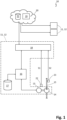
- FIG. 1 and 2 A block diagram of an embodiment of a device 10 is shown in a highly schematic manner.
- the device 10 has a flow generation device 11 for generating a fluid flow, which can be a gas flow or a liquid flow.
- the flow generation device 11 is embodied as a compressor 12.
- the compressor 12 has an electric motor 13 and a compressor unit 14 driven by the electric motor 13.
- the compressor unit 14 When the electric motor 13 is operating, the compressor unit 14 generates a fluid flow in a flow channel 15.
- other flow generation devices 11 can also be used, such as a pump or a fan.
- the flow generation device 11 also has a control unit 16 for controlling the electric motor 13.
- the control unit 16 can also be integrated into the electric motor 13 as an add-on unit or built-in unit.
- the control unit 16 can be, for example, a microprocessor or another electrical and/or electronic controller configured to execute program commands for controlling the electric motor 13.
- the control unit 16 can be communicatively connected to a memory 17 in which a program and/or parameters and/or data used for control can be stored.
- the flow generation device 11 can have a communication interface 18, which can be part of the control unit 16 or with which the control unit 16 is communicatively connected. Via the communication interface 18, the flow generation device 11 can be communicatively connected to an external computing device 19.
- the external computing device 19 can assume some of the control tasks for controlling the flow generation device 11 (here: compressor 12) and in particular the electric motor 13.
- the external computing device 19 it is also possible for the external computing device 19 to assume all control tasks, eliminating the need for the control unit 16.
- the memory 17 it is also possible for the memory 17 to be communicatively connected to the communication interface 18 either indirectly via the control unit 16 or directly.
- the external computing device 19 can be provided, for example, in the form of an Internet service or cloud service 20.
- a communication connection can be established between the communication interface 18 and the cloud service 20, for example, a wireless and/or wired Internet connection according to a standard communication protocol.
- the cloud service 20 can also provide storage capacity in the form of a cloud storage 21.
- the computing device 19 and/or the cloud storage 21 and/or the cloud service 20 can be communicatively connected to several identically or similarly constructed flow generation devices 11 or compressors 12. be, as shown schematically in the Figures 1 and 2 is shown.
- the device 10 has at least one sensor for each flow generating device 11.
- a first sensor 22 and a second sensor 23 are shown.
- Each sensor 22, 23 is configured to provide a sensor signal S1, S2 that describes a vibration.
- the first sensor 22 generates a first sensor signal S1
- the second sensor 23 generates a second sensor signal S2.
- the vibration is generated by the operation of the flow generation device 11 directly at the flow generation device 11 and/or a component mechanically and/or fluidically connected thereto, such as the flow channel 15.
- Each of the sensors 22, 23 can measure the vibration according to a suitable physical principle, for example, sound caused by the vibration (structure-borne sound and/or airborne sound). At least one of the sensors 22, 23 can be a non-contact measuring sensor, for example, a microphone or a vibrometer. At least one of the sensors 22, 23 can be a contact-measuring sensor, for example, an acceleration sensor or piezo sensor. The sensors 22, 23 can be based on the same or different physical measuring principles. The number of sensors 22, 23 can vary depending on the design of the flow generation device 11 and the associated parts conducting the fluid flow (e.g., flow channel 15). If multiple sensors 22, 23 are present, they can be arranged at different measuring points. For example, the first sensor 22 is directly arranged on a housing of the flow generating device 11. The second sensor 23 can be arranged directly on the flow channel 15.
- the sensor signals S1, S2, which describe the vibration caused by the flow generation device 11, are provided to the communication interface 18.
- the sensor signals S1, S2 can be provided to the cloud service 20 or the external computing device 19 via the communication interface 18.
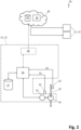
- the sensor signals S1, S2 can also be provided to the control unit 16 directly or via the communication interface 18.
- the embodiment of the device 10 according to Figure 2 corresponds essentially to the embodiment of the device 10 from Figure 1 The difference is that in the example according to Figure 2 the sensor signals S1, S2 are provided directly to the control unit 16.
- the communication interface 18 and the external computing device 19 or the cloud service 20 connected thereto can be optionally present, but can also be omitted. Otherwise, the embodiment according to Figure 2 according to the embodiment Figure 1 be implemented accordingly, so that reference can be made to the above description.
- control functions of the flow generation device 11 can be carried out either exclusively by the internal control unit 16 or exclusively by the external computing device 19 or in Cooperation between the internal control unit 16 and the external computing device 19 can be assumed.
- a control device of the device 10 can be implemented solely by the control unit 16, solely by the computing unit 19, or by a combination of the control unit 16 and the computing device 19.
- the reference to the control device 16, 19 is intended to encompass all implementation forms.
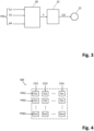
- the at least one sensor signal S1, S2 and the at least one parameter describing the operating point AP are contained in input parameters PIN, which are provided to the control device 16, 19.
- the control device 16, 19 is configured to determine a parameter relationship F from these input parameters PIN, which links the input parameters PIN with at least one control parameter CO.
- the determination of this parameter relationship F is in Figure 3 schematically illustrated by the first function block 30.
- the relationship F can be represented by a mathematical relationship, a characteristic map, one or more tables or by structures of artificial intelligence (AI), such as an artificial neural network.
- AI artificial intelligence
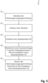
- a parameter relationship F is represented in the form of a parameter matrix MX, which links the input parameters PIN (PIN1, PIN2, ..., PINm) with one or more control parameters CO (CO1, CO2, ..., COn).
- the matrix elements fij of the parameter matrix MX or generally speaking the parameter context F is not immutable, but adaptive and can, for example, adapt to changed external circumstances or boundary conditions.
- a changed relationship F between the input parameters PIN and the at least one control parameter CO can arise.
- This can be detected by the at least one sensor signal S1, S2, which describes the caused vibration, changing at one or more operating points AP of the flow generation device 11.
- the sensor-detected vibration can therefore have a changed characteristic, for example a changed amplitude and/or a changed frequency.
- Such changes can be responded to according to the invention because the relationship F is adaptive.
- the matrix elements fij are variable and can be individually changed, allowing the parameter relationship F to be adapted between one or more of the input parameters PIN and one or more of the control parameters CO.
- each matrix element fij links exactly one input parameter PINi with exactly one control parameter COj. If there is no relationship between an input parameter PINi and the associated control parameter COj, the relevant matrix element can also be set to the value "zero".
- the matrix elements fij can generally describe any mathematical and/or logical relationship (linear, non-linear, continuous, discontinuous, etc.).
- At least one control parameter CO can be determined what in Figure 3 is schematically illustrated by the second functional block 31.
- the at least one control parameter CO can then be used to control the flow generation device 11 and, for example, the electric motor 13.
- the control device 16, 19 can utilize methods and/or structures of artificial intelligence (AI).
- AI artificial intelligence
- AI structures and/or AI methods can be used, such as knowledge-based systems, machine learning, in particular "deep learning.”
- the control device 16, 19 can have AI structures, such as an artificial neural network (ANN) and/or a support vector machine (SVM). All known AI methods and/or AI systems can be used.
- ANN artificial neural network
- SVM support vector machine
- a first method step V1 the flow generation device 11 (for example, the compressor 12) is operated and a fluid flow is generated.
- the operation of the flow generation device 11 generates a vibration that can be detected by the at least one sensor 22, 23 (second method step V2).
- the operating point AP of the flow generation device 11 is determined, which can be characterized by one or more electrical and/or mechanical parameters, for example the electrical operating parameters of the electric motor 13.
- the second process step V2 and the third process step V3 can be carried out in any order one after the other or in parallel.
- a parameter relationship F between the input parameters PIN and the at least one control parameter CO is determined (fourth method step V4).
- the parameter relationship F can be selected from a plurality of provided parameter relationships F selected and/or modified based on a given parameter relationship F and/or determined in any other suitable manner. It is possible to check the currently used parameter relationship F in a time-controlled and/or event-controlled manner and to adapt it if necessary.
- the parameter relationship F is determined or optimized in such a way that induced vibrations are reduced or eliminated.
- the determination of the parameter relationship F can be based on patterns and/or models and/or simulation results and/or empirically determined data that are characteristic of the operating point AP at which the flow generation device 11 is currently operating and that minimize the resulting vibration.
- the at least one control parameter CO is then determined depending on the input parameters PIN (fourth method step V4).
- a fifth method step V5 the determined at least one control parameter CO is used to control the flow generation device 11, in particular the electric motor 13.
- the invention relates to a method V and a device 10 for controlling a flow generating device 11, in particular a compressor 12.
- a vibration and/or an oscillation is generated, which is detected by at least one sensor 22, 23 and by at least a sensor signal S1, S2 is described.
- a relationship F between input parameters PIN and at least one control parameter CO is determined based on the at least one sensor signal S1, S2 and a current operating point AP of the flow generation device 11.
- the relationship F can, for example, be a parameter matrix MX or any other mathematical and/or logical structure that links the input parameters PIN with the at least one control parameter CO, for example an adaptive logical structure or a logical structure that can be changed by machine learning. This allows changing circumstances, in particular aging effects, to be taken into account.
- the at least one control parameter CO determined based on the relationship F is used to control the flow generation device 11, in particular an electric motor 13.
Landscapes
- Engineering & Computer Science (AREA)
- General Engineering & Computer Science (AREA)
- Mechanical Engineering (AREA)
- Software Systems (AREA)
- Theoretical Computer Science (AREA)
- Evolutionary Computation (AREA)
- Medical Informatics (AREA)
- Physics & Mathematics (AREA)
- Computing Systems (AREA)
- Data Mining & Analysis (AREA)
- General Physics & Mathematics (AREA)
- Mathematical Physics (AREA)
- Computer Vision & Pattern Recognition (AREA)
- Artificial Intelligence (AREA)
- Computer Hardware Design (AREA)
- Control Of Electric Motors In General (AREA)
- Control Of Positive-Displacement Pumps (AREA)
Applications Claiming Priority (1)
| Application Number | Priority Date | Filing Date | Title |
|---|---|---|---|
| DE102023124932.0A DE102023124932A1 (de) | 2023-09-15 | 2023-09-15 | Verfahren und Vorrichtung zur Steuerung einer Strömungserzeugungseinrichtung |
Publications (3)
| Publication Number | Publication Date |
|---|---|
| EP4524400A1 true EP4524400A1 (fr) | 2025-03-19 |
| EP4524400B1 EP4524400B1 (fr) | 2025-10-29 |
| EP4524400C0 EP4524400C0 (fr) | 2025-10-29 |
Family
ID=92708910
Family Applications (1)
| Application Number | Title | Priority Date | Filing Date |
|---|---|---|---|
| EP24198654.6A Active EP4524400B1 (fr) | 2023-09-15 | 2024-09-05 | Procede et dispositif de commande d'un dispositif de production d'ecoulement |
Country Status (2)
| Country | Link |
|---|---|
| EP (1) | EP4524400B1 (fr) |
| DE (1) | DE102023124932A1 (fr) |
Cited By (1)
| Publication number | Priority date | Publication date | Assignee | Title |
|---|---|---|---|---|
| CN120401175A (zh) * | 2025-07-03 | 2025-08-01 | 珠海格力电器股份有限公司 | 织物处理设备的振动检测电路、振幅控制方法及设备 |
Citations (10)
| Publication number | Priority date | Publication date | Assignee | Title |
|---|---|---|---|---|
| GB2255421A (en) * | 1991-05-02 | 1992-11-04 | * Norm Pacific Automation Corporation | Noise control of air conditioner |
| DE102012104052A1 (de) | 2011-05-11 | 2012-11-15 | Denso Corporation | Elektromotor mit Permanentmagneten in dessen Stator |
| US9279431B2 (en) * | 2011-12-02 | 2016-03-08 | Nuovo Pignone S.P.A. | Method and equipment for detecting rotating stall and compressor |
| DE102019122218A1 (de) | 2018-08-20 | 2020-02-20 | Nidec Corporation | Motorsteuerungseinheit und Servolenkungsvorrichtung |
| DE102020201200A1 (de) | 2020-01-31 | 2021-08-05 | Robert Bosch Gesellschaft mit beschränkter Haftung | Verfahren und Vorrichtung zur Regelung einer elektrischen Maschine |
| DE102020201203A1 (de) | 2020-01-31 | 2021-08-05 | Robert Bosch Gesellschaft mit beschränkter Haftung | Verfahren und Vorrichtung zur Drehzahlregelung einer elektrischen Maschine für den Antrieb eines Kompressors einer Wärmpepumpe |
| WO2022117615A2 (fr) | 2020-12-01 | 2022-06-09 | Robert Bosch Gmbh | Procédé pour déterminer une information de correction, procédé pour commander une machine électrique, appareil, dispositif d'entraînement électrique, pompe à chaleur |
| WO2022117274A1 (fr) | 2020-12-01 | 2022-06-09 | Robert Bosch Gmbh | Procédé d'optimisation du bruit dans un appareil de machine comprenant une machine électrique |
| DE102021132969A1 (de) | 2020-12-18 | 2022-06-23 | Lg Electronics Inc. | Kleidungsbehandlungsvorrichtung und das Steuerverfahren dafür |
| DE102022100004A1 (de) | 2021-01-05 | 2022-07-07 | Lg Electronics Inc. | Einrichtung zum steuern eines motors und verfahren zum steuern eines motors |
Family Cites Families (7)
| Publication number | Priority date | Publication date | Assignee | Title |
|---|---|---|---|---|
| DE60305263T2 (de) | 2002-06-19 | 2007-03-29 | Wavecrest Laboratories, Llc | Adaptive architektur der regelung für elektrische maschinen |
| DE102008025596B4 (de) * | 2008-05-28 | 2020-06-10 | Robert Bosch Gmbh | Verfahren zum Betrieb einer Einrichtung |
| DE102011050018A1 (de) * | 2011-04-29 | 2012-10-31 | Allweiler Gmbh | Pumpen-System |
| DE112014005404T5 (de) * | 2013-11-26 | 2016-08-11 | Tokuyama Corporation | Zustandsüberwachungssystem einer Bewegungsvorrichtung |
| AT518106B1 (de) * | 2016-01-26 | 2017-10-15 | Engel Austria Gmbh | Hydraulische Antriebseinheit und Verfahren zum Betreiben |
| DE102016105877B4 (de) * | 2016-03-31 | 2021-03-11 | Fibro Gmbh | Verfahren und Vorrichtung zur Überwachung einer Maschine |
| EP4293228A1 (fr) * | 2022-06-14 | 2023-12-20 | Burckhardt Compression AG | Procédé de prévision de la durée de vie résiduelle d'un ensemble joint d'étanchéité d'un compresseur à piston |
-
2023
- 2023-09-15 DE DE102023124932.0A patent/DE102023124932A1/de active Pending
-
2024
- 2024-09-05 EP EP24198654.6A patent/EP4524400B1/fr active Active
Patent Citations (10)
| Publication number | Priority date | Publication date | Assignee | Title |
|---|---|---|---|---|
| GB2255421A (en) * | 1991-05-02 | 1992-11-04 | * Norm Pacific Automation Corporation | Noise control of air conditioner |
| DE102012104052A1 (de) | 2011-05-11 | 2012-11-15 | Denso Corporation | Elektromotor mit Permanentmagneten in dessen Stator |
| US9279431B2 (en) * | 2011-12-02 | 2016-03-08 | Nuovo Pignone S.P.A. | Method and equipment for detecting rotating stall and compressor |
| DE102019122218A1 (de) | 2018-08-20 | 2020-02-20 | Nidec Corporation | Motorsteuerungseinheit und Servolenkungsvorrichtung |
| DE102020201200A1 (de) | 2020-01-31 | 2021-08-05 | Robert Bosch Gesellschaft mit beschränkter Haftung | Verfahren und Vorrichtung zur Regelung einer elektrischen Maschine |
| DE102020201203A1 (de) | 2020-01-31 | 2021-08-05 | Robert Bosch Gesellschaft mit beschränkter Haftung | Verfahren und Vorrichtung zur Drehzahlregelung einer elektrischen Maschine für den Antrieb eines Kompressors einer Wärmpepumpe |
| WO2022117615A2 (fr) | 2020-12-01 | 2022-06-09 | Robert Bosch Gmbh | Procédé pour déterminer une information de correction, procédé pour commander une machine électrique, appareil, dispositif d'entraînement électrique, pompe à chaleur |
| WO2022117274A1 (fr) | 2020-12-01 | 2022-06-09 | Robert Bosch Gmbh | Procédé d'optimisation du bruit dans un appareil de machine comprenant une machine électrique |
| DE102021132969A1 (de) | 2020-12-18 | 2022-06-23 | Lg Electronics Inc. | Kleidungsbehandlungsvorrichtung und das Steuerverfahren dafür |
| DE102022100004A1 (de) | 2021-01-05 | 2022-07-07 | Lg Electronics Inc. | Einrichtung zum steuern eines motors und verfahren zum steuern eines motors |
Cited By (1)
| Publication number | Priority date | Publication date | Assignee | Title |
|---|---|---|---|---|
| CN120401175A (zh) * | 2025-07-03 | 2025-08-01 | 珠海格力电器股份有限公司 | 织物处理设备的振动检测电路、振幅控制方法及设备 |
Also Published As
| Publication number | Publication date |
|---|---|
| EP4524400B1 (fr) | 2025-10-29 |
| EP4524400C0 (fr) | 2025-10-29 |
| DE102023124932A1 (de) | 2025-03-20 |
Similar Documents
| Publication | Publication Date | Title |
|---|---|---|
| DE102006045820B4 (de) | Verfahren und Vorrichtung zur automatischen Einstellung eines Motorreglers | |
| DE102016010056B4 (de) | Motorsteuervorrichtung, bereitgestellt mit einer Magnetflusssteuereinheit und Maschinenlernvorrichtung, und Verfahren davon | |
| DE102016013985A1 (de) | Vorrichtung für maschinelles Lernen und Verfahren zum Optimieren der Laufruhe des Vorschubs der Vorschubachse einer Maschine und eine die Vorrichtung für maschinelles Lernen umfassende Motorsteuervorrichtung | |
| DE102016010049A1 (de) | Vorrichtung für maschinelles Lernen und Verfahren zum Lernen einer vorhergesagten Lebensdauer eines Motors, Lebensdauer-Vorhersagevorrichtung und Motorsystem mit einer Vorrichtung für maschinelles Lernen | |
| DE102016008990A1 (de) | Maschinenlernvorrichtung zum Einlernen einer Verstärkungsoptimierung, Motorsteuervorrichtung mit Maschinenlernvorrichtung und Maschinenlernverfahren | |
| DE102016009031A1 (de) | Motorsteuervorrichtung mit Magnetflusssteuerung und Maschinenlernvorrichtung und Verfahren dafür | |
| EP4524400B1 (fr) | Procede et dispositif de commande d'un dispositif de production d'ecoulement | |
| DE102020200635A1 (de) | Maschinenlernsystem, Steuervorrichtung und Maschinenlernverfahren für das Optimieren von Filterkoeffizienten | |
| DE102016007404A1 (de) | Servosteuervorrichtung mit Funktion zur Online-Optimierung der Regelungsverstärkung unter Verwendung einer Bewertungsfunktion | |
| EP4299904B1 (fr) | Procédé de régulation de pompes à fluide à vitesse variable | |
| EP2923837B1 (fr) | Procédé de réduction de la charge de pointe dans une presse | |
| EP3593449B1 (fr) | Procédé de régulation d'une machine électrique, dispositif de régulation pour une machine électrique et système d'entraînement électrique | |
| DE102010053098A1 (de) | Verfahren zur Überwachung eines Rotorlagegebers | |
| EP2757384A2 (fr) | Procédé et dispositif de détection de fautes dans une machine électrique | |
| EP2903153B1 (fr) | Analyse des vibrations et des bruits d'une machine électrique alimentée par un convertisseur | |
| DE102012024273A1 (de) | Verfahren zum Abstimmen belastungsabhängiger Prozesse bei Windenergieanlagen und Mittel zu dessen Implementierung | |
| EP3151072B1 (fr) | Procede et systeme de reconnaissance de defaut et de surveillance pour un composant de machine commande ou regle electroniquement | |
| DE102004021645A1 (de) | Vorrichtung zum Prüfen von Maschinenbauteilen | |
| DE102015212685A1 (de) | Verfahren zur Optimierung einer Ansteuerung eines elektrischen Antriebssystems | |
| EP2602676A1 (fr) | Détermination de composants de friction d'un système d'entraînement | |
| EP2199879A1 (fr) | Dispositif et procédé de minimisation d'une erreur de suivi dynamique | |
| DE102008013521A1 (de) | Verfahren und Vorrichtung zur Anlaufsteuerung eines sensorlosen, bürstenlosen Gleichstrom-Motors | |
| WO2016016304A1 (fr) | Procédé de commande motrice d'un moteur synchrone à réluctance pour une pompe et pompe avec moteur synchrone à réluctance | |
| DE102020201203A1 (de) | Verfahren und Vorrichtung zur Drehzahlregelung einer elektrischen Maschine für den Antrieb eines Kompressors einer Wärmpepumpe | |
| EP2169482A2 (fr) | Dispositif et procédé de réglage d'un entraînement hydraulique avec un régulateur Sliding Mode |
Legal Events
| Date | Code | Title | Description |
|---|---|---|---|
| PUAI | Public reference made under article 153(3) epc to a published international application that has entered the european phase |
Free format text: ORIGINAL CODE: 0009012 |
|
| STAA | Information on the status of an ep patent application or granted ep patent |
Free format text: STATUS: REQUEST FOR EXAMINATION WAS MADE |
|
| 17P | Request for examination filed |
Effective date: 20250116 |
|
| AK | Designated contracting states |
Kind code of ref document: A1 Designated state(s): AL AT BE BG CH CY CZ DE DK EE ES FI FR GB GR HR HU IE IS IT LI LT LU LV MC ME MK MT NL NO PL PT RO RS SE SI SK SM TR |
|
| GRAP | Despatch of communication of intention to grant a patent |
Free format text: ORIGINAL CODE: EPIDOSNIGR1 |
|
| STAA | Information on the status of an ep patent application or granted ep patent |
Free format text: STATUS: GRANT OF PATENT IS INTENDED |
|
| GRAJ | Information related to disapproval of communication of intention to grant by the applicant or resumption of examination proceedings by the epo deleted |
Free format text: ORIGINAL CODE: EPIDOSDIGR1 |
|
| STAA | Information on the status of an ep patent application or granted ep patent |
Free format text: STATUS: REQUEST FOR EXAMINATION WAS MADE |
|
| RIC1 | Information provided on ipc code assigned before grant |
Ipc: F04C 28/28 20060101ALI20250414BHEP Ipc: F04D 29/66 20060101ALI20250414BHEP Ipc: F04D 27/02 20060101ALI20250414BHEP Ipc: F04D 27/00 20060101ALI20250414BHEP Ipc: F04D 15/00 20060101ALI20250414BHEP Ipc: F04B 51/00 20060101ALI20250414BHEP Ipc: F04B 49/06 20060101AFI20250414BHEP |
|
| INTG | Intention to grant announced |
Effective date: 20250512 |
|
| GRAP | Despatch of communication of intention to grant a patent |
Free format text: ORIGINAL CODE: EPIDOSNIGR1 |
|
| STAA | Information on the status of an ep patent application or granted ep patent |
Free format text: STATUS: GRANT OF PATENT IS INTENDED |
|
| INTC | Intention to grant announced (deleted) | ||
| INTG | Intention to grant announced |
Effective date: 20250613 |
|
| GRAS | Grant fee paid |
Free format text: ORIGINAL CODE: EPIDOSNIGR3 |
|
| GRAA | (expected) grant |
Free format text: ORIGINAL CODE: 0009210 |
|
| STAA | Information on the status of an ep patent application or granted ep patent |
Free format text: STATUS: THE PATENT HAS BEEN GRANTED |
|
| AK | Designated contracting states |
Kind code of ref document: B1 Designated state(s): AL AT BE BG CH CY CZ DE DK EE ES FI FR GB GR HR HU IE IS IT LI LT LU LV MC ME MK MT NL NO PL PT RO RS SE SI SK SM TR |
|
| REG | Reference to a national code |
Ref country code: CH Ref legal event code: F10 Free format text: ST27 STATUS EVENT CODE: U-0-0-F10-F00 (AS PROVIDED BY THE NATIONAL OFFICE) Effective date: 20251029 Ref country code: GB Ref legal event code: FG4D Free format text: NOT ENGLISH |
|
| REG | Reference to a national code |
Ref country code: IE Ref legal event code: FG4D Free format text: LANGUAGE OF EP DOCUMENT: GERMAN |
|
| REG | Reference to a national code |
Ref country code: DE Ref legal event code: R096 Ref document number: 502024000344 Country of ref document: DE |
|
| U01 | Request for unitary effect filed |
Effective date: 20251030 |
|
| U07 | Unitary effect registered |
Designated state(s): AT BE BG DE DK EE FI FR IT LT LU LV MT NL PT RO SE SI Effective date: 20251106 |
|
| PG25 | Lapsed in a contracting state [announced via postgrant information from national office to epo] |
Ref country code: ES Free format text: LAPSE BECAUSE OF FAILURE TO SUBMIT A TRANSLATION OF THE DESCRIPTION OR TO PAY THE FEE WITHIN THE PRESCRIBED TIME-LIMIT Effective date: 20251029 |
|
| PG25 | Lapsed in a contracting state [announced via postgrant information from national office to epo] |
Ref country code: NO Free format text: LAPSE BECAUSE OF FAILURE TO SUBMIT A TRANSLATION OF THE DESCRIPTION OR TO PAY THE FEE WITHIN THE PRESCRIBED TIME-LIMIT Effective date: 20260129 |
|
| PG25 | Lapsed in a contracting state [announced via postgrant information from national office to epo] |
Ref country code: HR Free format text: LAPSE BECAUSE OF FAILURE TO SUBMIT A TRANSLATION OF THE DESCRIPTION OR TO PAY THE FEE WITHIN THE PRESCRIBED TIME-LIMIT Effective date: 20251029 |
|
| PG25 | Lapsed in a contracting state [announced via postgrant information from national office to epo] |
Ref country code: RS Free format text: LAPSE BECAUSE OF FAILURE TO SUBMIT A TRANSLATION OF THE DESCRIPTION OR TO PAY THE FEE WITHIN THE PRESCRIBED TIME-LIMIT Effective date: 20260129 |
|
| PG25 | Lapsed in a contracting state [announced via postgrant information from national office to epo] |
Ref country code: IS Free format text: LAPSE BECAUSE OF FAILURE TO SUBMIT A TRANSLATION OF THE DESCRIPTION OR TO PAY THE FEE WITHIN THE PRESCRIBED TIME-LIMIT Effective date: 20260228 |
|
| PG25 | Lapsed in a contracting state [announced via postgrant information from national office to epo] |
Ref country code: PL Free format text: LAPSE BECAUSE OF FAILURE TO SUBMIT A TRANSLATION OF THE DESCRIPTION OR TO PAY THE FEE WITHIN THE PRESCRIBED TIME-LIMIT Effective date: 20251029 |
|
| PG25 | Lapsed in a contracting state [announced via postgrant information from national office to epo] |
Ref country code: SM Free format text: LAPSE BECAUSE OF FAILURE TO SUBMIT A TRANSLATION OF THE DESCRIPTION OR TO PAY THE FEE WITHIN THE PRESCRIBED TIME-LIMIT Effective date: 20251029 |
|
| PLBI | Opposition filed |
Free format text: ORIGINAL CODE: 0009260 |
|
| PG25 | Lapsed in a contracting state [announced via postgrant information from national office to epo] |
Ref country code: CZ Free format text: LAPSE BECAUSE OF FAILURE TO SUBMIT A TRANSLATION OF THE DESCRIPTION OR TO PAY THE FEE WITHIN THE PRESCRIBED TIME-LIMIT Effective date: 20251029 |
|
| REG | Reference to a national code |
Ref country code: CH Ref legal event code: L10 Free format text: ST27 STATUS EVENT CODE: U-0-0-L10-L00 (AS PROVIDED BY THE NATIONAL OFFICE) Effective date: 20260722 |
|
| PG25 | Lapsed in a contracting state [announced via postgrant information from national office to epo] |
Ref country code: SK Free format text: LAPSE BECAUSE OF FAILURE TO SUBMIT A TRANSLATION OF THE DESCRIPTION OR TO PAY THE FEE WITHIN THE PRESCRIBED TIME-LIMIT Effective date: 20251029 |
|
| PLAX | Notice of opposition and request to file observation + time limit sent |
Free format text: ORIGINAL CODE: EPIDOSNOBS2 |