EP3242048A1 - Vorrichtung mit einem reibkontakt und verfahren zum betreiben einer vorrichtung mit einem reibkontakt - Google Patents
Vorrichtung mit einem reibkontakt und verfahren zum betreiben einer vorrichtung mit einem reibkontakt Download PDFInfo
- Publication number
- EP3242048A1 EP3242048A1 EP17164919.7A EP17164919A EP3242048A1 EP 3242048 A1 EP3242048 A1 EP 3242048A1 EP 17164919 A EP17164919 A EP 17164919A EP 3242048 A1 EP3242048 A1 EP 3242048A1
- Authority
- EP
- European Patent Office
- Prior art keywords
- lubricant
- region
- path
- contact
- contact body
- Prior art date
- Legal status (The legal status is an assumption and is not a legal conclusion. Google has not performed a legal analysis and makes no representation as to the accuracy of the status listed.)
- Granted
Links
- 238000000034 method Methods 0.000 title claims abstract description 13
- 239000000314 lubricant Substances 0.000 claims abstract description 205
- 230000000694 effects Effects 0.000 claims description 8
- 239000012530 fluid Substances 0.000 claims description 8
- 238000009751 slip forming Methods 0.000 claims description 3
- 238000007599 discharging Methods 0.000 claims description 2
- 238000001816 cooling Methods 0.000 description 11
- 238000011161 development Methods 0.000 description 10
- 230000018109 developmental process Effects 0.000 description 10
- 239000000463 material Substances 0.000 description 4
- 239000003570 air Substances 0.000 description 3
- 238000005461 lubrication Methods 0.000 description 3
- 239000012080 ambient air Substances 0.000 description 2
- 230000008901 benefit Effects 0.000 description 2
- 239000002826 coolant Substances 0.000 description 2
- 230000017525 heat dissipation Effects 0.000 description 2
- 230000006872 improvement Effects 0.000 description 2
- 230000007246 mechanism Effects 0.000 description 2
- 230000037361 pathway Effects 0.000 description 2
- 239000007787 solid Substances 0.000 description 2
- 230000001427 coherent effect Effects 0.000 description 1
- 230000005494 condensation Effects 0.000 description 1
- 238000009833 condensation Methods 0.000 description 1
- 230000007423 decrease Effects 0.000 description 1
- 230000001419 dependent effect Effects 0.000 description 1
- 238000010586 diagram Methods 0.000 description 1
- 230000005489 elastic deformation Effects 0.000 description 1
- 238000001704 evaporation Methods 0.000 description 1
- 230000008020 evaporation Effects 0.000 description 1
- 230000020169 heat generation Effects 0.000 description 1
- 230000001771 impaired effect Effects 0.000 description 1
- 230000001788 irregular Effects 0.000 description 1
- 238000004519 manufacturing process Methods 0.000 description 1
- 230000008569 process Effects 0.000 description 1
Images


Classifications
-
- F—MECHANICAL ENGINEERING; LIGHTING; HEATING; WEAPONS; BLASTING
- F16—ENGINEERING ELEMENTS AND UNITS; GENERAL MEASURES FOR PRODUCING AND MAINTAINING EFFECTIVE FUNCTIONING OF MACHINES OR INSTALLATIONS; THERMAL INSULATION IN GENERAL
- F16N—LUBRICATING
- F16N7/00—Arrangements for supplying oil or unspecified lubricant from a stationary reservoir or the equivalent in or on the machine or member to be lubricated
- F16N7/38—Arrangements for supplying oil or unspecified lubricant from a stationary reservoir or the equivalent in or on the machine or member to be lubricated with a separate pump; Central lubrication systems
- F16N7/40—Arrangements for supplying oil or unspecified lubricant from a stationary reservoir or the equivalent in or on the machine or member to be lubricated with a separate pump; Central lubrication systems in a closed circulation system
-
- F—MECHANICAL ENGINEERING; LIGHTING; HEATING; WEAPONS; BLASTING
- F16—ENGINEERING ELEMENTS AND UNITS; GENERAL MEASURES FOR PRODUCING AND MAINTAINING EFFECTIVE FUNCTIONING OF MACHINES OR INSTALLATIONS; THERMAL INSULATION IN GENERAL
- F16H—GEARING
- F16H57/00—General details of gearing
- F16H57/04—Features relating to lubrication or cooling or heating
- F16H57/042—Guidance of lubricant
- F16H57/043—Guidance of lubricant within rotary parts, e.g. axial channels or radial openings in shafts
- F16H57/0431—Means for guiding lubricant directly onto a tooth surface or to foot areas of a gear, e.g. by holes or grooves in a tooth flank
-
- F—MECHANICAL ENGINEERING; LIGHTING; HEATING; WEAPONS; BLASTING
- F16—ENGINEERING ELEMENTS AND UNITS; GENERAL MEASURES FOR PRODUCING AND MAINTAINING EFFECTIVE FUNCTIONING OF MACHINES OR INSTALLATIONS; THERMAL INSULATION IN GENERAL
- F16N—LUBRICATING
- F16N39/00—Arrangements for conditioning of lubricants in the lubricating system
- F16N39/02—Arrangements for conditioning of lubricants in the lubricating system by cooling
Definitions
- the invention relates to a device with a frictional contact.
- the invention further relates to a method for operating a device with a frictional contact.
- cooling contacts or tribological contacts convective cooling mechanisms such as heatsinks are known in which a heat transfer to an ambient fluid, usually air, is improved by a large surface area.
- heat pipes that transport large heat flows from a warm place to a cold place are considered to be known. These are based on the evaporation / condensation principle and must therefore be completely closed.
- cooling circuits which include a return of a cooling medium are known in a wide variety of applications.
- the heat is mainly generated by solid state contacts, when friction bodies move relative to each other and touch each other at least on Asperiten. Heat is also caused by shear of the lubricant involved and elastic deformation of the body involved. Ideally, heat generation should be minimized. If this encounters technical-technical limits, heat must be dissipated. This happens mainly via heat conduction or convection.
- a heat transfer to an ambient air is - at least in the immediate vicinity of the frictional contact - in real components usually limited.
- the removal of the heat generated in frictional contact is therefore usually mainly on the heat conduction of the solids involved, especially if they have high specific heat conductivities. Materials with significantly lower thermal conductivities are close or in the range of the thermal conductivity of common lubricants. In this case, the heat conduction in the lubricant contributes to a similar extent as in the contact bodies for heat dissipation.
- the EP 25 08 778 A2 discloses a gear which is mounted in a rotation axis and on whose circumference preferably a plurality of teeth for transmitting a torque to a counter-element cooperating with the gear are arranged, wherein a friction region between a tooth and the counter-element is provided on a tooth flank surface with lubricant. It is provided that a longitudinal groove for supplying the lubricant in the direction of the friction plate is formed on the tooth flank surface.
- the present invention provides a device with a frictional contact, wherein a lubricant supply has a lubricant path, with a first region in which a heat released therein by a lubricant is absorbable, and with a second region in which the absorbed by the lubricant is deliverable.
- the present invention further provides a method of operating a device having a frictional contact.
- the method includes receiving released heat by the lubricant in a first portion of a lubricant supply lubrication pathway.
- the method further includes dispensing heat absorbed by the lubricant in a second region of the lubricant path.
- An idea of the present invention is to increase a lubricant volume flow at the frictional contact over the prior art and thus to allow improved heat dissipation of heat released by the frictional contact with the lubricant. Due to the increased volume flow of the lubricant can also be reduced in an advantageous manner lack of lubrication conditions on the frictional contact. Due to the heat removal by the lubricant, it is also preferable for a lower temperature development at the friction contact, less wear, a higher efficiency, a longer life and fewer failures. Furthermore, current design limits can advantageously be shifted in terms of size and materials. Thus, for example, a size of the contact body can be selected smaller or the contact body can be made lighter. In addition, the materials used must have a lower temperature resistance or wear resistance. As a result, the production costs can be reduced in an advantageous manner.
- the first region of the lubricant path is arranged on and adjacent to the frictional contact, and the second region of the lubricant path is arranged on a section of the lubricant path that is substantially remote from the frictional contact.
- the lubricant has a first temperature in the first region of the lubricant path and a second temperature in the second region of the lubricant path which is lower than the first temperature. Due to the temperature gradient between the first region and the second region of the lubricant path, the heat absorbed by the lubricant can thus advantageously be transferred from the first region into the second region and released there.
- the lubricant path has an isotropic or anisotropic structuring formed at least in sections on a surface of the second contact body, wherein the structuring has at least one microchannel.
- an intermediate region is arranged in each case between the first region of the lubricant path and the second region of the lubricant path, wherein the at least one microchannel in the first region and the second region of the lubricant path has a surface-to-volume ratio between 30,000 and 250,000,000 m -1 .
- the microchannel advantageously has a large surface in relation to the volume over which heat can be released, the cooling being proportional to Size of the surface is done.
- the heat can be emitted, for example, to an ambient air and / or to the contact body in which the microchannel is embedded.
- the at least one Micro channel has a surface-to-volume ratio between 500 and 600,000 m -1 .
- the at least one microchannel has a plurality of axially arranged, continuously formed subdivisions.
- the frictional contact can be supplied with lubricant by a relative movement of the first contact body to the second contact body, whereby a fluid column of the lubricant arranged in the lubricant path can be conveyed in the direction of the relative movement by means of lubricant adhering to the first contact body is.
- the frictional contact is self-lubricating formed by the relative movement of the first contact body to the second contact body and thus advantageously requires no external device for generating a movement by a transport of the lubricant in the lubricant path.
- the frictional contact by a capillary effect on the surface of the second Contact body at least partially formed structuring for receiving lubricant with lubricant can be supplied.
- an alternative self-lubricating rubbing contact can be provided.
- Particularly advantageous in the use of the capillary effect is that with a tearing of the fluid column by the capillary effect continues to allow a continuous transport of the fluid column to the frictional contact.
- a temperature of the lubricant arranged in the second region of the lubricant path can be cooled by an air flow impinging on the second region of the lubricant path.
- the heat released in the first region can be released by the frictional contact.
- the heat released by the frictional contact can be advantageously absorbed by the lubricant.
- the lubricant supply is designed as a closed lubricant circuit.
- the lubricant can be cooled by circulation in the closed lubricant circuit and then fed back to the frictional contact.
- Fig. 1 shows a cross-sectional view of the device with a frictional contact according to a preferred embodiment of the invention.
- the device 1 preferably has a frictional contact 10 with a first contact body 12 and a second contact body 14.
- the first contact body 12 is preferably adjustable relative to the second contact body 14.
- a relative movement of the first contact body 12 to the second contact body 14 is rotational in the present embodiment.
- the relative movement of the first contact body 12 to the second contact body 14 may be translational, for example.
- the first contact body 12 preferably has a substantially round cross-section.
- the second contact body 14 preferably has a substantially planar cross-section.
- Adjacent to the friction contact 10 leading to the friction contact 10 lubricant supply 16 of the friction contact for supplying the friction contact 10 is arranged with lubricant 17.
- the lubricant supply 16 is preferably designed as a closed lubricant circuit. Alternatively, the lubricant supply 16 may be formed, for example, as an open lubricant path.
- the lubricant supply 16 has, at and adjacent to the frictional contact 10, a first region 18a of the lubricant path 18 and at a substantially remote from the frictional contact 10 (in FIG Fig. 1 not shown) portion of the lubricant path 18 on a second area.
- the first region 18 a of the lubricant path 18 is configured to receive heat released by the frictional contact 10 through the lubricant 17.
- the second (in Fig. 1 not shown) range of the lubricant path 18 is to designed to deliver heat absorbed by the lubricant 17 W to an environment.
- the friction contact 10 is preferably supplied by the relative movement of the first contact body 12 to the second contact body 14 with lubricant 17.
- lubricant 17 adhering to the first contact body 12 is designed to convey a fluid column of the lubricant 17, which is connected to the lubricant 17 and is arranged in the lubricant supply 16, in the direction of the relative movement.
- the lubricant supply 16 is preferably formed on a portion of the surface 14 a of the second contact body 14.
- the lubricant supply 16 may for example be formed on an entire surface of the second contact body 16 or have a dimension adapted to the volumetric requirement of the lubricant flow.
- the surface 14 a of the second contact body 14 preferably has a structuring 20 formed in sections to form the lubricant supply 16.
- the section-wise structuring 20 of the surface 14 a of the second contact body 14 preferably has a plurality of microchannels 21.
- a single microchannel 21 may be provided up to an arbitrary number of microchannels 21.
- the plurality of microchannels 21 are preferably arranged parallel to one another and terminate at a feed 23 of the frictional contact 10.
- the plurality of microchannels 21 of the lubricant supply 16 are furthermore preferably arranged as an extension of a flow F of the lubricant 17 through the frictional contact 10.
- the fluid column of the lubricant 17 arranged in the lubricant supply 16 preferably forms, together with the lubricant 17 adhering to the first friction body 12, a coherent fluid column.
- lubricant reservoir is preferably 17 nach chronologicalbar lubricant.
- the lubricant depot For example, be formed by the arranged in a lubricant path 18 of the lubricant supply 16 lubricant.
- the frictional contact 10 further preferably has an inlet 23 for supplying lubricant 17 and a drain 24 for discharging lubricant 17.
- the frictional contact 10 can be supplied with lubricant 17, for example, by a capillary effect of a structuring on the surface 14a of the second contact body 14 in sections for receiving lubricant 17.
- Fig. 2 shows a schematic representation of the device with the frictional contact according to the preferred embodiment of the invention.
- the lubricant supply 16 is preferably designed as a closed lubricant circuit.
- the lubricant supply 16 may be formed, for example, as an open lubricant path.
- the lubricant supply 16 has the lubricant path 18.
- the lubricant path 18 has the first region 18 a, in which heat W released by the frictional contact 10 can be absorbed by the lubricant 17.
- the lubricant path 18 furthermore has the second region 18b, in which the heat W absorbed by the lubricant 17 can be released.
- the first region 18 a of the lubricant path 18 is preferably arranged on and adjacent to the friction contact 10.
- the second region 18b of the lubricant path 18 is preferably located at a portion of the lubricant path 18 that is substantially remote from the friction contact 10 arranged.
- the lubricant 17 preferably has a first temperature T1 in the first region 18a of the lubricant path 18 and a second temperature T2 lower in the second region 18b of the lubricant path 18, which is lower than the first temperature T1, since no lubricant is present in the second region Heat is supplied more and the lubricant can cool in the second area.
- an intermediate region 18c, 18d is arranged in each case.
- a surface of the microchannels 21 of the lubricant path 18 is in Fig. 2 not shown.
- a surface to volume ratio of the microchannels 21 in the first region 18a and in the second region 18b of the lubricant path 18 is preferably between 30,000 and 250,000,000 m -1 .
- the surface-to-volume ratio of the microchannels 21 is preferably between 500 and 600,000 m -1 .
- the temperature T2 of the lubricant 17 arranged in the second area 18b of the lubricant path 18 can be cooled by an air flow Ls impinging on the second area 18b of the lubricant path 18.
- other cooling mechanisms or devices for cooling the lubricant arranged in the second region 18b of the lubricant 18 are conceivable.
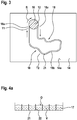
- Fig. 3 shows a schematic representation of the device with the frictional contact according to another preferred embodiment of the invention.
- the lubricant supply 16 is preferably designed as a closed lubricant circuit.
- the lubricant supply 16 may be formed, for example, as an open lubricant path.
- the first contact body 12 is arranged relative to the second contact body 14 such that an end face of the first contact body 12 contacts an end face of the second contact body 14.
- the frictional contact 10 is thus formed in the present embodiment in the region of the end face of the first contact body 12 and the end face of the second contact body 14 forming this contact.
- the first contact body 12 is preferably rotatably mounted in a direction of rotation R.
- the plurality of microchannels 21 extend as well as in relation to FIG Fig. 2 illustrated embodiment on the surface 14a of the second contact body 14 and form the lubricant path 18 from.
- the lubricant supply 16 has, on and adjacent to the frictional contact 10, the first region 18a of the lubricant path 18 and the second region 18b on a portion of the lubricant path 18 arranged substantially away from the frictional contact 10.
- the first region 18 a of the lubricant path 18 is configured to receive heat released by the frictional contact 10 through the lubricant 17.
- the second region 18b of the lubricant path 18 is designed to deliver heat W absorbed by the lubricant 17 to an environment.
- the lubricant 17 preferably has the first temperature T1 in the first region 18a of the lubricant path 18 and the second temperature T2 in the second region 18b of the lubricant path 18, which is lower than the first temperature T1, since the lubricant 17 in the second region no Heat is supplied more and the lubricant can cool in the second area.
- Fig. 4a shows a cross-sectional view of a micro-channel of a lubricant path of the device with the frictional contact according to another preferred embodiment of the invention.
- a single microchannel 21 is shown, which has a plurality of axially arranged, continuously formed subdivisions.
- further microchannels may be arranged adjacent to the single microchannel 21.
- the microchannel 21 in the present embodiment has a surface to volume ratio of preferably 30,000 and 250,000,000 m -1 .
- another suitable surface-to-volume ratio may be provided.
- the lubricant 17 disposed in the microchannel 21 advantageously has a large surface area O in relation to the volume V, which promotes a cooling effect of the lubricant 17.
- Fig. 4b shows a cross-sectional view of a micro-channel of a lubricant path of the device with the frictional contact according to another preferred embodiment of the invention.
- the microchannel 21 in the present embodiment has a surface to volume ratio of preferably 500 to 600,000 m -1 . Alternatively, for example, another suitable surface-to-volume ratio may be provided.
- This design of the microchannel 21 is advantageously used in the region of the intermediate regions 18 c, 18 d of the lubricant path 18.
- Fig. 4c shows a cross-sectional view of a micro-channel of a lubricant path of the device with the frictional contact according to another preferred embodiment of the invention.
- the microchannel 21 has an irregular cross-sectional geometry in the present embodiment.
- the surface-to-volume ratio is preferably 500 to 600,000 m -1 .
- a suitable surface-to-volume ratio may be provided. It is therefore advantageous to insert the microchannel 21 having the cross-sectional shape shown here in the respective intermediate regions 18c, 18d of the lubricant path 18 for transporting the thermal energy stored in the lubricant to the second region 18b.
- the intermediate region 18c With a small in relation to the volume V. Surface O compared to the first and second regions 18a, 18b, lubricant can thus be transported advantageously through the respective intermediate region 18c, without this much heat is dissipated.
- Fig. 5 shows a flowchart of a method for operating the device with the frictional contact according to the aforementioned embodiments of the invention.
- the method for operating the device with the frictional contact comprises displacing S1 a first contact body of the frictional contact into a movement relative to a second contact body of the frictional contact, while the frictional contact is supplied with lubricant by means of a lubricant supply.
- the method further includes receiving released heat heat S2 through the lubricant in a first portion of a lubricant supply lubrication pathway.
- the method further comprises dispensing S3 of heat absorbed by the lubricant in a second region of the lubricant path.
- a geometry of the structuring of the surface of the second contact body to structural requirements of the frictional contact or the first contact body and the second contact body adaptable.
Landscapes
- Engineering & Computer Science (AREA)
- General Engineering & Computer Science (AREA)
- Mechanical Engineering (AREA)
- Braking Arrangements (AREA)
- Lubricants (AREA)
- Friction Gearing (AREA)
- Mechanical Operated Clutches (AREA)
Abstract
Description
- Die Erfindung betrifft eine Vorrichtung mit einem Reibkontakt. Die Erfindung betrifft des Weiteren ein Verfahren zum Betreiben einer Vorrichtung mit einem Reibkontakt.
- Zur Kühlung von Kontakten bzw. tribologischen Kontakten sind konvektive Kühlmechanismen wie beispielsweise Kühlkörper bekannt, bei denen eine Wärmeabgabe an ein Umgebungsfluid, in der Regel Luft, durch eine große Oberfläche verbessert wird. Als bekannt gelten des Weiteren Wärmerohre, die große Wärmeströme von einem warmen Ort zu einem kalten Ort transportieren. Diese basieren auf dem Verdampfungs-/Kondensationsprinzip und müssen daher komplett geschlossen sein. Generell sind in verschiedensten Anwendungen Kühlkreisläufe, die eine Rückführung eines Kühlmediums einschließen, bekannt.
- In Reibkontakten wird eine Reibleistung zum größten Teil in Wärme umgesetzt. Dies führt zu einer Temperaturerhöhung der Kontaktpartner des Reibkontaktes und eines Schmierstoffes, wobei die Temperaturerhöhung in den meisten Anwendungsfällen ohne technischen Nutzen, in vielen Anwendungsfällen technisch nachteilig ist. Beispielsweise können Materialien aufschmelzen, erweichen oder anderweitig thermisch in Mitleidenschaft gezogen werden. Zudem kann über den Marangoni-Effekt eine Schmierstoffversorgung des Reibkontaktes beeinträchtigt werden bis hin zu einem Systemversagen.
- Die Wärme entsteht hauptsächlich durch Festkörperkontakte, wenn Reibkörper sich relativ zueinander bewegen und sich dabei zumindest an Asperiten berühren. Wärme entsteht aber auch durch Scherung des beteiligten Schmierstoffes sowie durch elastische Verformung der beteiligten Körper. Idealerweise ist die Wärmeentstehung zu minimieren. Wenn dies an technischwirtschaftliche Grenzen stößt, ist Wärme abzuführen. Dies geschieht hauptsächlich über Wärmeleitung oder Konvektion.
- Eine Wärmeübertragung an eine Umgebungsluft ist - zumindest in unmittelbarer Nähe des Reibkontaktes - in realen Bauteilen zumeist eingeschränkt. Die Abfuhr der im Reibkontakt entstehenden Wärme erfolgt deswegen in der Regel hauptsächlich über die Wärmeleitung der beteiligten Festkörper, insbesondere wenn diese hohe spezifische Wärmeleitfähigkeiten aufweisen. Materialien mit deutlich niedrigeren Wärmeleitzahlen liegen nahe oder im Bereich der Wärmeleitfähigkeit von gängigen Schmierstoffen. In diesem Fall trägt die Wärmeleitung im Schmierstoff in ähnlichem Maße wie die in den Kontaktkörpern zur Wärmeabfuhr bei.
- Die
EP 25 08 778 A2 offenbart ein Zahnrad, das in einer Drehachse gelagert ist und an dessen Umfang bevorzugt eine Vielzahl von Zähnen zum Übertragen eines Drehmoments an ein mit dem Zahnrad zusammenwirkendes Gegenelement angeordnet sind, wobei ein Reibbereich zwischen einem Zahn und dem Gegenelement an einer Zahnflankenoberfläche mit Schmiermittel versehen ist. Es ist vorgesehen, dass an der Zahnflankenoberfläche eine Längsrille zur Zuführung des Schmiermittels in Richtung zum Reibblech ausgebildet ist. - Die vorliegende Erfindung schafft eine Vorrichtung mit einem Reibkontakt, wobei eine Schmiermittelversorgung einen Schmiermittelweg aufweist, mit einem ersten Bereich, in welchem eine darin freigesetzte Wärme durch ein Schmiermittel aufnehmbar ist, und mit einem zweiten Bereich, in welchem die durch das Schmiermittel aufgenommene abgebbar ist.
- Die vorliegende Erfindung schafft des Weiteren ein Verfahren zum Betreiben einer Vorrichtung mit einem Reibkontakt. Das Verfahren umfasst ein Aufnehmen von freigesetzter Wärme durch das Schmiermittel in einem ersten Bereich eines Schmiermittelwegs der Schmiermittelversorgung. Das Verfahren umfasst des Weiteren ein Abgeben von durch das Schmiermittel aufgenommener Wärme in einem zweiten Bereich des Schmiermittelwegs.
- Eine Idee der vorliegenden Erfindung ist es, einen Schmiermittel-Volumenstrom am Reibkontakt gegenüber dem Stand der Technik zu erhöhen und damit eine verbesserte Wärmeabfuhr von durch den Reibkontakt freigesetzter Wärme mit dem Schmiermittel zu ermöglichen. Durch den erhöhten Volumenstrom des Schmiermittels können des Weiteren in vorteilhafter Weise Mangelschmierungszustände am Reibkontakt verringert werden. Durch die Wärmeabfuhr durch das Schmiermittel kommt es des Weiteren vorzugsweise zu einer geringeren Temperaturentwicklung am Reibkontakt, weniger Verschleiß, einem höheren Wirkungsgrad, einer höheren Lebensdauer sowie weniger Ausfällen. Des Weiteren können in vorteilhafter Weise aktuelle Designgrenzen was Baugröße und Materialien betrifft verschoben werden. So kann beispielsweise eine Baugröße der Kontaktkörper kleiner gewählt werden bzw. die Kontaktkörper leichter ausgebildet sein. Darüber hinaus müssen die verwendeten Materialien eine geringere Temperaturbeständigkeit bzw. Verschleißfestigkeit aufweisen. Dadurch können in vorteilhafter Weise die Herstellungskosten reduziert werden.
- Vorteilhafte Ausführungsformen und Weiterbildungen ergeben sich aus den Unteransprüchen sowie aus der Beschreibung unter Bezugnahme auf die Figuren.
- Gemäß einer bevorzugten Weiterbildung ist vorgesehen, dass der erste Bereich des Schmiermittelwegs an und benachbart zu dem Reibkontakt angeordnet ist, und der zweite Bereich des Schmiermittelwegs an einem, im Wesentlichen entfernt von dem Reibkontakt angeordneten Abschnitt des Schmiermittelwegs angeordnet ist. Somit kann in vorteilhafter Weise gewährleistet werden, dass die durch den Reibkontakt freigesetzte und durch das Schmiermittel aufgenommene Wärme in dem zweiten, entfernt von dem Reibkontakt angeordneten Bereich des Schmiermittelwegs Wärme abgebbar ist.
- Gemäß einer weiteren bevorzugten Weiterbildung ist vorgesehen, dass das Schmiermittel in dem ersten Bereich des Schmiermittelwegs eine erste Temperatur und in dem zweiten Bereich des Schmiermittelwegs eine zweite Temperatur aufweist, welche geringer als die erste Temperatur ist. Aufgrund des Temperaturgefälles zwischen dem ersten Bereich und dem zweiten Bereich des Schmiermittelwegs kann somit in vorteilhafter Weise die durch das Schmiermittel aufgenommene Wärme von dem ersten Bereich in den zweiten Bereich übertragen und dort abgegeben werden.
- Gemäß einer weiteren bevorzugten Weiterbildung ist vorgesehen, dass der Schmiermittelweg eine an einer Oberfläche des zweiten Kontaktkörpers zumindest abschnittsweise ausgebildete isotrope oder anisotrope Strukturierung aufweist, wobei die Strukturierung zumindest einen Mikrokanal aufweist. Durch Vorsehen des zumindest einen Mikrokanals kann in vorteilhafter Weise ein verbesserter und strömungsgünstigerer Transport des Schmiermittels in dem Schmiermittelweg ermöglicht werden.
- Gemäß einer weiteren bevorzugten Weiterbildung ist vorgesehen, dass zwischen dem ersten Bereich des Schmiermittelwegs und dem zweiten Bereich des Schmiermittelwegs jeweils ein Zwischenbereich angeordnet ist, wobei der zumindest eine Mikrokanal in dem ersten Bereich und dem zweiten Bereich des Schmiermittelwegs ein Oberfläche-zu-Volumen-Verhältnis zwischen 30.000 und 250.000.000 m-1 aufweist. Durch Vorsehen des zumindest einen Mikrokanals mit einem Oberfläche-zu-Volumen-Verhältnis zwischen 30.000 und 250.000.000 m-1 weist der Mikrokanal in vorteilhafter Weise eine in Relation zum Volumen große Oberfläche auf, über welche Wärme abgebbar ist, wobei die Abkühlung proportional zur Größe der Oberfläche erfolgt. Die Wärme ist beispielsweise an eine Umgebungsluft und/oder an den Kontaktkörper abgebbar, in welchen der Mikrokanal eingebettet ist.
- Gemäß einer weiteren bevorzugten Weiterbildung ist vorgesehen, dass in dem jeweiligen Zwischenbereich des Schmiermittelwegs der zumindest eine Mikrokanal ein Oberfläche-zu-Volumen-Verhältnis zwischen 500 und 600.000 m-1 aufweist. Durch Vorsehen des Zwischenbereichs mit einer in Relation zum Volumen geringen Oberfläche im Vergleich zu dem ersten und zweiten Bereich kann Schmiermittel somit in vorteilhafter Weise durch den jeweiligen Zwischenbereich transportiert werden, ohne dass hierbei viel Wärme abgeführt wird. Bei wachsendem Volumen nimmt das Oberfläche-zu-Volumen-Verhältnis bei allen Körpern ab, da die Oberfläche quadratisch, das Volumen jedoch kubisch wächst. Das ist von Bedeutung für die Abkühlungsgeschwindigkeit verschieden großer Massen. Die Abkühlung erfolgt proportional zur Größe der Oberfläche, die beim Größerwerden jedoch langsamer wächst als das Volumen, so dass größere Massen langsamer abkühlen als kleine. Dies ist beispielsweise dann vorteilhaft, wenn in dem jeweiligen Zwischenbereich des Schmiermittelwegs andere Komponenten verbaut sind, die nicht erwärmt werden sollen.
- Gemäß einer weiteren bevorzugten Weiterbildung ist vorgesehen, dass zumindest in dem ersten Bereich des Schmiermittelwegs und dem zweiten Bereich des Schmiermittelwegs der zumindest eine Mikrokanal eine Mehrzahl von in Axialrichtung angeordneten, durchgehend ausgebildeten Unterteilungen aufweist. Durch Vorsehen der Unterteilungen des Mikrokanals kann somit eine Verbesserung eines Kapillareffekts des Mikrokanals erzielt werden.
- Gemäß einer weiteren bevorzugten Weiterbildung ist vorgesehen, dass der Reibkontakt durch eine Relativbewegung des ersten Kontaktkörpers zu dem zweiten Kontaktkörper mit Schmiermittel versorgbar ist, wobei durch an dem ersten Kontaktkörper anhaftendes Schmiermittel eine damit verbundene, in dem Schmiermittelweg angeordnete Fluidsäule des Schmiermittels in Richtung der Relativbewegung förderbar ist. Somit ist der Reibkontakt durch die Relativbewegung des ersten Kontaktkörpers zu dem zweiten Kontaktkörper selbstschmierend ausgebildet und benötigt somit in vorteilhafter Weise keine externe Vorrichtung zum Erzeugen einer Bewegung durch einen Transport des Schmiermittels im Schmiermittelweg.
- Gemäß einer weiteren bevorzugten Weiterbildung ist vorgesehen, dass der Reibkontakt durch einen Kapillareffekt einer an der Oberfläche des zweiten Kontaktkörpers zumindest abschnittsweise ausgebildeten Strukturierung zur Aufnahme von Schmiermittel mit Schmiermittel versorgbar ist. Somit kann in vorteilhafter Weise ein alternativer selbstschmierender Reibkontakt bereitgestellt werden. Besonders vorteilhaft bei der Nutzung des Kapillareffekts ist, dass bei einem Reißen der Fluidsäule durch den Kapillareffekt weiterhin ein fortlaufender Transport der Fluidsäule zum Reibkontakt ermöglicht werden kann.
- Gemäß einer weiteren bevorzugten Weiterbildung ist vorgesehen, dass eine Temperatur des in dem zweiten Bereich des Schmiermittelwegs angeordneten Schmiermittels durch eine auf den zweiten Bereich des Schmiermittelwegs auftreffende Luftströmung kühlbar ist. Somit wird in vorteilhafter Weise nicht nur der Schmiermittelweg zur Kühlung des Schmiermittels verwendet, sondern ebenfalls ein weiteres externes Kühlmedium. Dadurch kann eine zusätzliche Verbesserung der Kühlung der Temperatur des Schmiermittels erreicht werden.
- Gemäß einer weiteren bevorzugten Weiterbildung ist vorgesehen, dass die in dem ersten Bereich freigesetzte Wärme durch den Reibkontakt freisetzbar ist. Somit ist die durch den Reibkontakt freigesetzte Wärme in vorteilhafter Weise durch das Schmiermittel aufnehmbar.
- Gemäß einer weiteren bevorzugten Weiterbildung ist vorgesehen, dass die Schmiermittelversorgung als geschlossener Schmiermittelkreislauf ausgebildet ist. Somit kann das Schmiermittel durch Zirkulation in dem geschlossenen Schmiermittelkreislauf abgekühlt und anschließend dem Reibkontakt wieder zugeführt werden.
- Die beschriebenen Ausgestaltungen und Weiterbildungen lassen sich beliebig miteinander kombinieren.
- Weitere mögliche Ausgestaltungen, Weiterbildungen und Implementierungen der Erfindung umfassen auch nicht explizit genannte Kombinationen von zuvor oder im Folgenden bezüglich der Ausführungsbeispiele beschriebenen Merkmale der Erfindung.
- Die beiliegenden Zeichnungen sollen ein weiteres Verständnis der Ausführungsformen der Erfindung vermitteln. Sie veranschaulichen Ausführungsformen und dienen im Zusammenhang mit der Beschreibung der Erklärung von Prinzipien und Konzepten der Erfindung.
- Andere Ausführungsformen und viele der genannten Vorteile ergeben sich im Hinblick auf die Zeichnungen. Die dargestellten Elemente der Zeichnungen sind nicht notwendigerweise maßstabsgetreu zueinander gezeigt.
- Es zeigen:
- Fig. 1
- eine Querschnittsdarstellung einer Vorrichtung mit einem Reibkontakt gemäß einer bevorzugten Ausführungsform der Erfindung;
- Fig. 2
- eine schematische Darstellung der Vorrichtung mit dem Reibkontakt gemäß der bevorzugten Ausführungsform der Erfindung;
- Fig. 3
- eine schematische Darstellung der Vorrichtung mit dem Reibkontakt gemäß einer weiteren bevorzugten Ausführungsform der Erfindung;
- Fig. 4a
- eine Querschnittsdarstellung eines Mikrokanals eines Schmiermittelwegs der Vorrichtung mit dem Reibkontakt gemäß einer weiteren bevorzugten Ausführungsform der Erfindung;
- Fig. 4b
- eine Querschnittsdarstellung eines Mikrokanals eines Schmiermittelwegs der Vorrichtung mit dem Reibkontakt gemäß einer weiteren bevorzugten Ausführungsform der Erfindung;
- Fig. 4c
- eine Querschnittsdarstellung eines Mikrokanals eines Schmiermittelwegs der Vorrichtung mit dem Reibkontakt gemäß einer weiteren bevorzugten Ausführungsform der Erfindung;
- Fig. 5
- ein Ablaufdiagramm eines Verfahrens zum Betreiben der Vorrichtung mit dem Reibkontakt gemäß der vorstehend genannten Ausführungsformen der Erfindung.
- In den Figuren der Zeichnungen bezeichnen gleiche Bezugszeichen gleiche oder funktionsgleiche Elemente, Bauteile oder Komponenten, soweit nichts Gegenteiliges angegeben ist.
-
Fig. 1 zeigt eine Querschnittsdarstellung der Vorrichtung mit einem Reibkontakt gemäß einer bevorzugten Ausführungsform der Erfindung. - Die Vorrichtung 1 weist vorzugsweise einen Reibkontakt 10 mit einem ersten Kontaktkörper 12 und einem zweiten Kontaktkörper 14 auf. Der erste Kontaktkörper 12 ist vorzugsweise relativ zum zweiten Kontaktkörper 14 verstellbar. Eine Relativbewegung des ersten Kontaktkörpers 12 zum zweiten Kontaktkörper 14 ist in der vorliegenden Ausführungsform rotatorisch. Alternativ kann die Relativbewegung des ersten Kontaktkörpers 12 zum zweiten Kontaktkörper 14 beispielsweise translatorisch sein.
- Der erste Kontaktkörper 12 weist vorzugsweise einen im Wesentlichen runden Querschnitt auf. Der zweite Kontaktkörper 14 weist vorzugsweise einen im Wesentlichen ebenen Querschnitt auf. Benachbart zu dem Reibkontakt 10 ist eine zu dem Reibkontakt 10 führende Schmiermittelversorgung 16 des Reibkontaktes zum Versorgen des Reibkontaktes 10 mit Schmiermittel 17 angeordnet. Die Schmiermittelversorgung 16 ist vorzugsweise als geschlossener Schmiermittelkreislauf ausgebildet. Alternativ kann die Schmiermittelversorgung 16 beispielsweise als offener Schmiermittelweg ausgebildet sein.
Die Schmiermittelversorgung 16 weist an und benachbart zu dem Reibkontakt 10 einen ersten Bereich 18a des Schmiermittelwegs 18 und an einem, im Wesentlichen entfernt von dem Reibkontakt 10 angeordneten (inFig. 1 nicht gezeigten) Abschnitt des Schmiermittelwegs 18 einen zweiten Bereich auf. - Der erste Bereich 18a des Schmiermittelwegs 18 ist dazu ausgebildet, durch den Reibkontakt 10 freigesetzte Wärme W durch das Schmiermittel 17 aufzunehmen. Der zweite (in
Fig. 1 nicht gezeigte) Bereich des Schmiermittelwegs 18 ist dazu ausgebildet, durch das Schmiermittel 17 aufgenommene Wärme W an eine Umgebung abzugeben. - Der Reibkontakt 10 ist vorzugsweise durch die Relativbewegung des ersten Kontaktkörpers 12 zu dem zweiten Kontaktkörper 14 mit Schmiermittel 17 versorgbar. An dem ersten Kontaktkörper 12 anhaftendes Schmiermittel 17 ist dabei dazu ausgebildet, eine mit dem Schmiermittel 17 verbundene, in der Schmiermittelversorgung 16 angeordnete Fluidsäule des Schmiermittels 17 in Richtung der Relativbewegung zu fördern.
- Die Schmiermittelversorgung 16 ist vorzugsweise an einem Abschnitt der Oberfläche 14a des zweiten Kontaktkörpers 14 ausgebildet. Alternativ kann die Schmiermittelversorgung 16 beispielsweise an einer gesamten Oberfläche des zweiten Kontaktkörpers 16 ausgebildet sein oder eine je nach volumetrischer Anforderung des Schmiermittelstroms angepasste Dimension aufweisen.
- Die Oberfläche 14a des zweiten Kontaktkörpers 14 weist zum Ausbilden der Schmiermittelversorgung 16 vorzugsweise eine abschnittsweise ausgebildete Strukturierung 20 auf. Die abschnittsweise Strukturierung 20 der Oberfläche 14a des zweiten Kontaktkörpers 14 weist vorzugsweise eine Mehrzahl von Mikrokanälen 21 auf. Alternativ kann beispielsweise ein einzelner Mikrokanal 21 bis zu einer beliebigen Anzahl von Mikrokanälen 21 vorgesehen sein. Die Mehrzahl von Mikrokanälen 21 sind vorzugsweise parallel zueinander angeordnet und enden an einem Zulauf 23 des Reibkontaktes 10. Die Mehrzahl von Mikrokanälen 21 der Schmiermittelversorgung 16 sind des Weiteren vorzugsweise in Verlängerung eines Flusses F des Schmiermittels 17 durch den Reibkontakt 10 angeordnet.
- Die in der Schmiermittelversorgung 16 angeordnete Fluidsäule des Schmiermittels 17 bildet vorzugsweise zusammen mit dem an dem ersten Reibkörper 12 anhaftenden Schmiermittel 17 eine zusammenhängende Fluidsäule aus. Aus einem (in
Fig. 1 nicht gezeigten) mit der Schmiermittelversorgung 16 verbundenen Schmiermitteldepot ist vorzugsweise Schmiermittel 17 nachförderbar. Alternativ kann das Schmiermitteldepot beispielsweise durch das in einem Schmiermittelweg 18 der Schmiermittelversorgung 16 angeordnete Schmiermittel ausgebildet sein. - Durch die Relativbewegung des ersten Kontaktkörpers 12 zu dem zweiten Kontaktkörper 14 ist somit in vorteilhafter Weise Schmiermittel in Richtung der Relativbewegung förderbar. Der Reibkontakt 10 weist des Weiteren vorzugsweise einen Zulauf 23 zum Zuführen von Schmiermittel 17 und einen Ablauf 24 zum Abführen von Schmiermittel 17 auf. Somit ist durch die Relativbewegung des ersten Kontaktkörpers 12 zu dem zweiten Kontaktkörper 14 eine erforderliche Menge an Schmiermittel 17 zu dem Reibkontakt zuführbar und von dem Reibkontakt 10 abführbar.
- Alternativ oder zusätzlich zu der vorstehend genannten Ausführungsform kann der Reibkontakt 10 beispielsweise durch einen Kapillareffekt einer an der Oberfläche 14a des zweiten Kontaktkörpers 14 abschnittsweise ausgebildeten Strukturierung zur Aufnahme von Schmiermittel 17 mit Schmiermittel 17 versorgt werden.
-
Fig. 2 zeigt eine schematische Darstellung der Vorrichtung mit dem Reibkontakt gemäß der bevorzugten Ausführungsform der Erfindung. - Die Schmiermittelversorgung 16 ist vorzugsweise als geschlossener Schmiermittelkreislauf ausgebildet. Alternativ kann die Schmiermittelversorgung 16 beispielsweise als offener Schmiermittelweg ausgebildet sein.
- Die Schmiermittelversorgung 16 weist den Schmiermittelweg 18 auf. Der Schmiermittelweg 18 weist den ersten Bereich 18a auf, in welchem durch den Reibkontakt 10 freigesetzte Wärme W durch das Schmiermittel 17 aufnehmbar ist. Der Schmiermittelweg 18 weist des Weiteren den zweiten Bereich 18b auf, in welchem die durch das Schmiermittel 17 aufgenommene Wärme W abgebbar ist.
- Der erste Bereich 18a des Schmiermittelwegs 18 ist vorzugsweise an und benachbart zu dem Reibkontakt 10 angeordnet. Der zweite Bereich 18b des Schmiermittelwegs 18 ist vorzugsweise an einem, im Wesentlichen entfernt von dem Reibkontakt 10 angeordneten Abschnitt des Schmiermittelwegs 18 angeordnet. Das Schmiermittel 17 weist vorzugsweise in dem ersten Bereich 18a des Schmiermittelwegs 18 eine erste Temperatur T1 und in dem zweiten Bereich 18b des Schmiermittelwegs 18 eine zweite Temperatur T2 auf, welche geringer als die erste Temperatur T1 ist, da dem Schmiermittel 17 in dem zweiten Bereich keine Wärme mehr zugeführt wird und das Schmiermittel in dem zweiten Bereich abkühlen kann.
- Zwischen dem ersten Bereich 18a des Schmiermittelwegs 18 und dem zweiten Bereich 18b des Schmiermittelwegs 18 ist jeweils ein Zwischenbereich 18c, 18d angeordnet. Eine Oberfläche der Mikrokanäle 21 des Schmiermittelwegs 18 ist in
Fig. 2 nicht dargestellt. Ein Oberfläche-zu-Volumen-Verhältnis der Mikrokanäle 21 in dem ersten Bereich 18a und in dem zweiten Bereich 18b des Schmiermittelwegs 18 beträgt vorzugsweise zwischen 30.000 und 250.000.000 m-1. In den Zwischenbereichen 18c, 18d des Schmiermittelwegs 18 beträgt das Oberfläche-zu-Volumen-Verhältnis der Mikrokanäle 21 vorzugsweise zwischen 500 und 600.000 m-1. Somit kann in den Zwischenbereichen die in dem Schmiermittel 17 gespeicherte Wärmeenergie mit dem Schmiermittel 17 transportiert und in dem ersten und zweiten Bereich 18a, 18b des Schmiermittelwegs 18 Wärme abgegeben werden. - Darüber hinaus ist die Temperatur T2 des in dem zweiten Bereich 18b des Schmiermittelwegs 18 angeordneten Schmiermittels 17 durch eine auf den zweiten Bereich 18b des Schmiermittelwegs 18 auftreffende Luftströmung Ls kühlbar. Alternativ sind auch andere Kühlmechanismen bzw. Vorrichtungen zur Kühlung des in dem zweiten Bereich 18b des Schmiermittelwegs 18 angeordneten Schmiermittels denkbar.
-
Fig. 3 zeigt eine schematische Darstellung der Vorrichtung mit dem Reibkontakt gemäß einer weiteren bevorzugten Ausführungsform der Erfindung. - Die Schmiermittelversorgung 16 ist vorzugsweise als geschlossener Schmiermittelkreislauf ausgebildet. Alternativ kann die Schmiermittelversorgung 16 beispielsweise als offener Schmiermittelweg ausgebildet sein.
- In der vorliegenden Ausführungsform ist der erste Kontaktkörper 12 zu dem zweiten Kontaktkörper 14 derart angeordnet, dass eine Stirnfläche des ersten Kontaktkörpers 12 eine Stirnfläche des zweiten Kontaktkörpers 14 kontaktiert. Der Reibkontakt 10 ist in der vorliegenden Ausführungsform somit im Bereich der Stirnfläche des ersten Kontaktkörpers 12 und der mit dieser kontakt bildenden Stirnfläche des zweiten Kontaktkörpers 14 ausgebildet.
- Der erste Kontaktkörper 12 ist vorzugsweise in einer Drehrichtung R drehbar gelagert. Die Mehrzahl von Mikrokanälen 21 verlaufen wie auch in der mit Bezug auf
Fig. 2 dargestellten Ausführungsform an der Oberfläche 14a des zweiten Kontaktkörpers 14 und bilden den Schmiermittelweg 18 aus. - Die Schmiermittelversorgung 16 weist an und benachbart zu dem Reibkontakt 10 den ersten Bereich 18a des Schmiermittelwegs 18 und an einem, im Wesentlichen entfernt von dem Reibkontakt 10 angeordneten Abschnitt des Schmiermittelwegs 18 den zweiten Bereich 18b auf.
- Der erste Bereich 18a des Schmiermittelwegs 18 ist dazu ausgebildet, durch den Reibkontakt 10 freigesetzte Wärme W durch das Schmiermittel 17 aufzunehmen.
- Der zweite Bereich 18b des Schmiermittelwegs 18 ist dazu ausgebildet, durch das Schmiermittel 17 aufgenommene Wärme W an eine Umgebung abzugeben.
- Das Schmiermittel 17 weist vorzugsweise in dem ersten Bereich 18a des Schmiermittelwegs 18 die erste Temperatur T1 und in dem zweiten Bereich 18b des Schmiermittelwegs 18 die zweite Temperatur T2 auf, welche geringer als die erste Temperatur T1 ist, da dem Schmiermittel 17 in dem zweiten Bereich keine Wärme mehr zugeführt wird und das Schmiermittel in dem zweiten Bereich abkühlen kann.
-
Fig. 4a zeigt eine Querschnittsdarstellung eines Mikrokanals eines Schmiermittelwegs der Vorrichtung mit dem Reibkontakt gemäß einer weiteren bevorzugten Ausführungsform der Erfindung. In der vorliegenden Darstellung ist ein einzelner Mikrokanal 21 gezeigt, welcher eine Mehrzahl von in Axialrichtung angeordneten, durchgehend ausgebildeten Unterteilungen aufweist. Alternativ können benachbart zu dem einzelnen Mikrokanal 21 beispielsweise weitere Mikrokanäle angeordnet sein. Der Mikrokanal 21 weist in der vorliegenden Ausführungsform ein Oberfläche-zu-Volumen-Verhältnis von vorzugsweise 30.000 und 250.000.000 m-1 auf. Alternativ kann beispielsweise ein anderes geeignetes Oberfläche-zu-Volumen-Verhältnis vorgesehen sein. Somit weist das in dem Mikrokanal 21 angeordnete Schmiermittel 17 in vorteilhafter Weise eine in Relation zum Volumen V große Oberfläche O auf, was eine Kühlwirkung des Schmiermittels 17 begünstigt. -
Fig. 4b zeigt eine Querschnittsdarstellung eines Mikrokanals eines Schmiermittelwegs der Vorrichtung mit dem Reibkontakt gemäß einer weiteren bevorzugten Ausführungsform der Erfindung. Der Mikrokanal 21 weist in der vorliegenden Ausführungsform ein Oberfläche-zu-Volumen-Verhältnis von vorzugsweise 500 bis 600.000 m-1 auf. Alternativ kann beispielsweise ein anderes geeignetes Oberfläche-zu-Volumen-Verhältnis vorgesehen sein. Diese Ausbildung des Mikrokanals 21 wird in vorteilhafter Weise im Bereich der Zwischenbereiche 18c, 18d des Schmiermittelwegs 18 eingesetzt. -
Fig. 4c zeigt eine Querschnittsdarstellung eines Mikrokanals eines Schmiermittelwegs der Vorrichtung mit dem Reibkontakt gemäß einer weiteren bevorzugten Ausführungsform der Erfindung. Der Mikrokanal 21 weist in der vorliegenden Ausführungsform eine unregelmäßige Querschnittsgeometrie auf. Das Oberfläche-zu-Volumen-Verhältnis beträgt vorzugsweise 500 bis 600.000 m-1. - Alternativ kann beispielsweise ein anderes geeignetes Oberfläche-zu-Volumen-Verhältnis vorgesehen sein. Es ist daher vorteilhaft, den Mikrokanal 21 mit der vorliegend gezeigten Querschnittsform in den jeweiligen Zwischenbereichen 18c, 18d des Schmiermittelwegs 18 zum Transport der in dem Schmiermittel gespeicherten Wärmeenergie zu dem zweiten Bereich 18b einzusetzen Durch Vorsehen des Zwischenbereichs 18c mit einer in Relation zum Volumen V geringen Oberfläche O im Vergleich zu dem ersten und zweiten Bereich 18a, 18b kann Schmiermittel somit in vorteilhafter Weise durch den jeweiligen Zwischenbereich 18c transportiert werden, ohne dass hierbei viel Wärme abgeführt wird.
-
Fig. 5 zeigt ein Ablaufdiagramm eines Verfahrens zum Betreiben der Vorrichtung mit dem Reibkontakt gemäß der vorstehend genannten Ausführungsformen der Erfindung. - Das Verfahren zum Betreiben der Vorrichtung mit dem Reibkontakt umfasst ein Versetzen S1 eines ersten Kontaktkörpers des Reibkontaktes in eine Bewegung relativ zu einem zweiten Kontaktkörper des Reibkontaktes, während der Reibkontakt mittels einer Schmiermittelversorgung mit Schmiermittel versorgt wird. Das Verfahren umfasst überdies ein Aufnehmen S2 von freigesetzter Wärme durch das Schmiermittel in einem ersten Bereich eines Schmiermittelwegs der Schmiermittelversorgung. Das Verfahren umfasst des Weiteren ein Abgeben S3 von durch das Schmiermittel aufgenommener Wärme in einem zweiten Bereich des Schmiermittelwegs.
- Obwohl die vorliegende Erfindung anhand bevorzugter Ausführungsbeispiele vorstehend beschrieben wurde, ist sie nicht darauf beschränkt, sondern auf vielfältige Art und Weise modifizierbar. Insbesondere lässt sich die Erfindung in mannigfaltiger Weise verändern oder modifizieren, ohne vom Kern der Erfindung abzuweichen.
- Beispielsweise ist eine Geometrie der Strukturierung der Oberfläche des zweiten Kontaktkörpers an bauliche Anforderungen des Reibkontaktes bzw. des ersten Kontaktkörpers und des zweiten Kontaktkörpers anpassbar.
Claims (13)
- Vorrichtung (1) mit einem Reibkontakt (10), mit einem ersten Kontaktkörper (12) und einem zweiten Kontaktkörper (14), wobei der erste Kontaktkörper (12) relativ zum zweiten Kontaktkörper (14) verstellbar ist, und mit einer Schmiermittelversorgung (16) des Reibkontaktes (10), mittels welcher der Reibkontakt (10) mit Schmiermittel (17) versorgbar ist, dadurch gekennzeichnet, dass die Schmiermittelversorgung (16) einen Schmiermittelweg (18) aufweist, mit einem ersten Bereich (18a), in welchem eine darin freigesetzte Wärme (W) durch das Schmiermittel (17) aufnehmbar ist, und mit einem zweiten Bereich (18b), in welchem die durch das Schmiermittel (17) aufgenommene Wärme (W) abgebbar ist.
- Vorrichtung nach Anspruch 1, dadurch gekennzeichnet, dass der erste Bereich (18a) des Schmiermittelwegs (18) an und benachbart zu dem Reibkontakt (10) angeordnet ist, und der zweite Bereich (18b) des Schmiermittelwegs (18) an einem, im Wesentlichen entfernt von dem Reibkontakt (10) angeordneten Abschnitt des Schmiermittelwegs (18) angeordnet ist.
- Vorrichtung nach Anspruch 1 oder 2, dadurch gekennzeichnet, dass das Schmiermittel (17) in dem ersten Bereich (18a) des Schmiermittelwegs (18) eine erste Temperatur (T1) und in dem zweiten Bereich (18b) des Schmiermittelwegs (18) eine zweite Temperatur (T2) aufweist, welche geringer als die erste Temperatur (T1) ist.
- Vorrichtung nach einem der vorhergehenden Ansprüchen, dadurch gekennzeichnet, dass der Schmiermittelweg (18) eine an einer Oberfläche (14a) des zweiten Kontaktkörpers (14) zumindest abschnittsweise ausgebildete isotrope oder anisotrope Strukturierung (20) aufweist, wobei die Strukturierung (20) zumindest einen Mikrokanal (21) aufweist.
- Vorrichtung nach Anspruch 4, dadurch gekennzeichnet, dass zwischen dem ersten Bereich (18a) des Schmiermittelwegs (18) und dem zweiten Bereich (18b) des Schmiermittelwegs (18) jeweils ein Zwischenbereich (18c, 18d) angeordnet ist, wobei der zumindest eine Mikrokanal (21) in dem ersten Bereich (18a) und dem zweiten Bereich (18b) des Schmiermittelwegs (18) ein Oberfläche-zu-Volumen-Verhältnis zwischen 30.000 und 250.000.000 m-1 aufweist.
- Vorrichtung nach Anspruch 5, dadurch gekennzeichnet, dass in dem jeweiligen Zwischenbereich (18c, 18d) des Schmiermittelwegs (18) der zumindest eine Mikrokanal ein Oberfläche-zu-Volumen-Verhältnis zwischen 500 und 600.000 m-1 aufweist.
- Vorrichtung nach einem der Ansprüche 4 bis 6, dadurch gekennzeichnet, dass zumindest in dem ersten Bereich (18a) des Schmiermittelwegs (18) und dem zweiten Bereich (18b) des Schmiermittelwegs (18) der zumindest eine Mikrokanal (21) eine Mehrzahl von in Axialrichtung angeordneten, durchgehend ausgebildeten Unterteilungen (22) aufweist.
- Vorrichtung nach einem der vorhergehenden Ansprüche, dadurch gekennzeichnet, dass der Reibkontakt (10) durch eine Relativbewegung des ersten Kontaktkörpers (12) zu dem zweiten Kontaktkörper (14) mit Schmiermittel (17) versorgbar ist, wobei durch an dem ersten Kontaktkörper (12) anhaftendes Schmiermittel (17) eine damit verbundene, in dem Schmiermittelweg (18) angeordnete Fluidsäule des Schmiermittels (17) in Richtung der Relativbewegung förderbar ist.
- Vorrichtung nach einem der Ansprüche 4 bis 7, dadurch gekennzeichnet, dass der Reibkontakt (10) durch einen Kapillareffekt einer an der Oberfläche (14a) des zweiten Kontaktkörpers (14) zumindest abschnittsweise ausgebildeten Strukturierung (20) zur Aufnahme von Schmiermittel (17) mit Schmiermittel (17) versorgbar ist.
- Vorrichtung nach einem der vorhergehenden Ansprüche, dadurch gekennzeichnet, dass eine Temperatur (T2) des in dem zweiten Bereich (18b) des Schmiermittelwegs (18) angeordneten Schmiermittels (17) durch eine auf den zweiten Bereich (18b) des Schmiermittelwegs (18) auftreffende Luftströmung (Ls) kühlbar ist.
- Vorrichtung nach einem der vorhergehenden Ansprüche, dadurch gekennzeichnet, dass die in dem ersten Bereich (18a) freigesetzte Wärme durch den Reibkontakt (10) freisetzbar ist.
- Vorrichtung nach einem der vorhergehenden Ansprüche, dadurch gekennzeichnet, dass die Schmiermittelversorgung (16) als geschlossener Schmiermittelkreislauf ausgebildet ist.
- Verfahren zum Betreiben einer Vorrichtung mit einem Reibkontakt (10), mit den Schritten:Versetzen (S1) eines ersten Kontaktkörpers (12) des Reibkontaktes (10) in eine Bewegung relativ zu einem zweiten Kontaktkörper (14) des Reibkontaktes (10), während der Reibkontakt (10) mittels einer Schmiermittelversorgung (16) mit Schmiermittel (17) versorgt wird;gekennzeichnet durch:Aufnehmen (S2) von freigesetzter Wärme (W) durch das Schmiermittel (17) in einem ersten Bereich (18a) eines Schmiermittelwegs (18) der Schmiermittelversorgung (16); undAbgeben (S3) von durch das Schmiermittel (17) aufgenommener Wärme (W) in einem zweiten Bereich (18b) des Schmiermittelwegs (18).
Applications Claiming Priority (1)
| Application Number | Priority Date | Filing Date | Title |
|---|---|---|---|
| DE102016206139.9A DE102016206139A1 (de) | 2016-04-13 | 2016-04-13 | Vorrichtung mit einem Reibkontakt und Verfahren zum Betreiben einer Vorrichtung mit einem Reibkontakt |
Publications (2)
| Publication Number | Publication Date |
|---|---|
| EP3242048A1 true EP3242048A1 (de) | 2017-11-08 |
| EP3242048B1 EP3242048B1 (de) | 2021-12-08 |
Family
ID=58638660
Family Applications (1)
| Application Number | Title | Priority Date | Filing Date |
|---|---|---|---|
| EP17164919.7A Not-in-force EP3242048B1 (de) | 2016-04-13 | 2017-04-05 | Vorrichtung mit einem reibkontakt und verfahren zum betreiben einer vorrichtung mit einem reibkontakt |
Country Status (3)
| Country | Link |
|---|---|
| EP (1) | EP3242048B1 (de) |
| CN (1) | CN107289117B (de) |
| DE (1) | DE102016206139A1 (de) |
Citations (6)
| Publication number | Priority date | Publication date | Assignee | Title |
|---|---|---|---|---|
| JPS5258355U (de) * | 1975-10-27 | 1977-04-27 | ||
| JPS5737192A (en) * | 1980-08-14 | 1982-03-01 | Toshiba Corp | Bearing device |
| EP0104159A2 (de) * | 1982-09-20 | 1984-03-28 | MIBA Gleitlager Aktiengesellschaft | Hydrodynamisches Gleitlager |
| EP2508778A2 (de) | 2011-03-28 | 2012-10-10 | Robert Bosch GmbH | Zahnrad sowie Getriebe-Antriebseinheit |
| EP2703662A1 (de) * | 2012-08-31 | 2014-03-05 | Daido Metal Company Ltd. | Pleuelstangenlager |
| WO2016047159A1 (ja) * | 2014-09-22 | 2016-03-31 | 三菱重工業株式会社 | 軸受及び軸受パッド |
Family Cites Families (9)
| Publication number | Priority date | Publication date | Assignee | Title |
|---|---|---|---|---|
| DE1810401A1 (de) * | 1968-11-22 | 1970-06-11 | V Teolotechniceskij Naucnoissl | Umlaufschmierung fuer selbstansaugende Gleitlager |
| US3723209A (en) * | 1970-12-25 | 1973-03-27 | Showa Denko Kk | Method for increasing wear resistance of a rubbing surface of aluminuum alloy articles |
| US7134939B2 (en) * | 2003-09-05 | 2006-11-14 | Fricso Ltd. | Method for reducing wear of mechanically interacting surfaces |
| WO2007064336A1 (en) * | 2005-12-02 | 2007-06-07 | United Technologies Corporation | Methods and systems to enhance efficiency of power-transmission systems containing higher viscosity lubricants |
| EP2002136A1 (de) * | 2006-03-31 | 2008-12-17 | Alstom Technology Ltd | Hydrodynamisches axialgleitlager und zugehöriges betriebsverfahren |
| CN101329009A (zh) * | 2008-07-24 | 2008-12-24 | 上海交通大学 | 基于摩擦副转换的太空机械零部件的固液混合润滑方法 |
| BRPI0902385A2 (pt) * | 2009-07-15 | 2011-03-09 | Mahle Metal Leve Sa | segmento e bronzina de mancal para motores de combustão interna de veìculos |
| US8343002B1 (en) * | 2011-06-20 | 2013-01-01 | GM Global Technology Operations LLC | Rotating planetary gear carrier lubrication device |
| CN202628820U (zh) * | 2012-04-09 | 2012-12-26 | 浙江大学 | 一种基体表面带微坑油包的滑动导轨 |
-
2016
- 2016-04-13 DE DE102016206139.9A patent/DE102016206139A1/de not_active Withdrawn
-
2017
- 2017-04-05 EP EP17164919.7A patent/EP3242048B1/de not_active Not-in-force
- 2017-04-12 CN CN201710236970.5A patent/CN107289117B/zh not_active Expired - Fee Related
Patent Citations (7)
| Publication number | Priority date | Publication date | Assignee | Title |
|---|---|---|---|---|
| JPS5258355U (de) * | 1975-10-27 | 1977-04-27 | ||
| JPS5737192A (en) * | 1980-08-14 | 1982-03-01 | Toshiba Corp | Bearing device |
| EP0104159A2 (de) * | 1982-09-20 | 1984-03-28 | MIBA Gleitlager Aktiengesellschaft | Hydrodynamisches Gleitlager |
| EP2508778A2 (de) | 2011-03-28 | 2012-10-10 | Robert Bosch GmbH | Zahnrad sowie Getriebe-Antriebseinheit |
| EP2703662A1 (de) * | 2012-08-31 | 2014-03-05 | Daido Metal Company Ltd. | Pleuelstangenlager |
| WO2016047159A1 (ja) * | 2014-09-22 | 2016-03-31 | 三菱重工業株式会社 | 軸受及び軸受パッド |
| EP3203096A1 (de) * | 2014-09-22 | 2017-08-09 | Mitsubishi Heavy Industries, Ltd. | Lager und lagerplatte |
Also Published As
| Publication number | Publication date |
|---|---|
| CN107289117B (zh) | 2022-04-22 |
| EP3242048B1 (de) | 2021-12-08 |
| CN107289117A (zh) | 2017-10-24 |
| DE102016206139A1 (de) | 2017-10-19 |
Similar Documents
| Publication | Publication Date | Title |
|---|---|---|
| EP2630381B1 (de) | Anordnung mit vorrichtungen zu integrierter kühlung und/oder heizung sowie ein verfahren zur integrierten beheizung oder kühlung | |
| EP2507527B1 (de) | Wälzlageranordnung | |
| DE102016202416B4 (de) | Rotorwellenanordnung und Verfahren zu dessen Herstellung | |
| DE102020214000B4 (de) | Zentrifuge mit elastokalorischer kühlung und verfahren zur kühlung einer zentrifuge | |
| EP2257235B1 (de) | Kryochirurgisches instrument | |
| DE10100719A1 (de) | Spannfutter zum Spannen von Werkzeugen durch Schrumpfsitz | |
| EP3788946A1 (de) | Vorrichtung zur wärmeableitung und verwendung einer solchen vorrichtung | |
| DE202007008221U1 (de) | Vorrichtung zur Übertragung von thermischer Energie | |
| DE102018127928A1 (de) | Wärmetransporteinheit | |
| DE102013001117B4 (de) | Radlager für die rotatorische Lagerung einer Radnabe eines Fahrzeugs | |
| EP1957813A1 (de) | Wälzlager mit heizelement | |
| EP3242048B1 (de) | Vorrichtung mit einem reibkontakt und verfahren zum betreiben einer vorrichtung mit einem reibkontakt | |
| EP3230673B1 (de) | Wärmeübertragendes ausgleichselement sowie elektrisch betreibbares fahrzeug mit derartigem ausgleichselement | |
| DE10305031A1 (de) | Wärmeübertrager mit wabenförmigen Strömungsspalten | |
| EP3367426A1 (de) | Halbleitermodul mit kühlkörper | |
| DE102018102576B4 (de) | Bremssattel einer Bremsanlage eines Fahrzeugs | |
| DE102023123751B3 (de) | Werkzeugmaschine mit Temperiersystem | |
| DE112013006173T5 (de) | Reifenschadenreparaturvorrichtung | |
| EP0548021A1 (de) | Kühlvorrichtung | |
| DE102023107125A1 (de) | Temperiervorrichtung und Elektronikbaugruppe | |
| DE102009034827A1 (de) | Wälzlager mit einem Käfig | |
| EP3085996B1 (de) | Getriebe und verfahren zum betrieb eines getriebes | |
| DE102016123192A1 (de) | Kühlkreislauf für eine Antriebseinheit eines elektrisch angetriebenen Fahrzeugs | |
| AT507217B1 (de) | Verfahren zur nutzung von wärme | |
| EP3242059A2 (de) | Vorrichtung mit einem reibkontakt und verfahren zum betreiben einer vorrichtung mit einem reibkontakt |
Legal Events
| Date | Code | Title | Description |
|---|---|---|---|
| PUAI | Public reference made under article 153(3) epc to a published international application that has entered the european phase |
Free format text: ORIGINAL CODE: 0009012 |
|
| STAA | Information on the status of an ep patent application or granted ep patent |
Free format text: STATUS: THE APPLICATION HAS BEEN PUBLISHED |
|
| AK | Designated contracting states |
Kind code of ref document: A1 Designated state(s): AL AT BE BG CH CY CZ DE DK EE ES FI FR GB GR HR HU IE IS IT LI LT LU LV MC MK MT NL NO PL PT RO RS SE SI SK SM TR |
|
| AX | Request for extension of the european patent |
Extension state: BA ME |
|
| STAA | Information on the status of an ep patent application or granted ep patent |
Free format text: STATUS: REQUEST FOR EXAMINATION WAS MADE |
|
| 17P | Request for examination filed |
Effective date: 20180508 |
|
| RBV | Designated contracting states (corrected) |
Designated state(s): AL AT BE BG CH CY CZ DE DK EE ES FI FR GB GR HR HU IE IS IT LI LT LU LV MC MK MT NL NO PL PT RO RS SE SI SK SM TR |
|
| RAP1 | Party data changed (applicant data changed or rights of an application transferred) |
Owner name: ROBERT BOSCH GMBH |
|
| GRAP | Despatch of communication of intention to grant a patent |
Free format text: ORIGINAL CODE: EPIDOSNIGR1 |
|
| STAA | Information on the status of an ep patent application or granted ep patent |
Free format text: STATUS: GRANT OF PATENT IS INTENDED |
|
| INTG | Intention to grant announced |
Effective date: 20210705 |
|
| GRAS | Grant fee paid |
Free format text: ORIGINAL CODE: EPIDOSNIGR3 |
|
| GRAA | (expected) grant |
Free format text: ORIGINAL CODE: 0009210 |
|
| STAA | Information on the status of an ep patent application or granted ep patent |
Free format text: STATUS: THE PATENT HAS BEEN GRANTED |
|
| AK | Designated contracting states |
Kind code of ref document: B1 Designated state(s): AL AT BE BG CH CY CZ DE DK EE ES FI FR GB GR HR HU IE IS IT LI LT LU LV MC MK MT NL NO PL PT RO RS SE SI SK SM TR |
|
| REG | Reference to a national code |
Ref country code: GB Ref legal event code: FG4D Free format text: NOT ENGLISH |
|
| REG | Reference to a national code |
Ref country code: AT Ref legal event code: REF Ref document number: 1454002 Country of ref document: AT Kind code of ref document: T Effective date: 20211215 Ref country code: CH Ref legal event code: EP |
|
| REG | Reference to a national code |
Ref country code: DE Ref legal event code: R096 Ref document number: 502017012174 Country of ref document: DE |
|
| REG | Reference to a national code |
Ref country code: IE Ref legal event code: FG4D Free format text: LANGUAGE OF EP DOCUMENT: GERMAN |
|
| REG | Reference to a national code |
Ref country code: LT Ref legal event code: MG9D |
|
| REG | Reference to a national code |
Ref country code: NL Ref legal event code: MP Effective date: 20211208 |
|
| PG25 | Lapsed in a contracting state [announced via postgrant information from national office to epo] |
Ref country code: RS Free format text: LAPSE BECAUSE OF FAILURE TO SUBMIT A TRANSLATION OF THE DESCRIPTION OR TO PAY THE FEE WITHIN THE PRESCRIBED TIME-LIMIT Effective date: 20211208 Ref country code: LT Free format text: LAPSE BECAUSE OF FAILURE TO SUBMIT A TRANSLATION OF THE DESCRIPTION OR TO PAY THE FEE WITHIN THE PRESCRIBED TIME-LIMIT Effective date: 20211208 Ref country code: FI Free format text: LAPSE BECAUSE OF FAILURE TO SUBMIT A TRANSLATION OF THE DESCRIPTION OR TO PAY THE FEE WITHIN THE PRESCRIBED TIME-LIMIT Effective date: 20211208 Ref country code: BG Free format text: LAPSE BECAUSE OF FAILURE TO SUBMIT A TRANSLATION OF THE DESCRIPTION OR TO PAY THE FEE WITHIN THE PRESCRIBED TIME-LIMIT Effective date: 20220308 |
|
| PG25 | Lapsed in a contracting state [announced via postgrant information from national office to epo] |
Ref country code: SE Free format text: LAPSE BECAUSE OF FAILURE TO SUBMIT A TRANSLATION OF THE DESCRIPTION OR TO PAY THE FEE WITHIN THE PRESCRIBED TIME-LIMIT Effective date: 20211208 Ref country code: NO Free format text: LAPSE BECAUSE OF FAILURE TO SUBMIT A TRANSLATION OF THE DESCRIPTION OR TO PAY THE FEE WITHIN THE PRESCRIBED TIME-LIMIT Effective date: 20220308 Ref country code: LV Free format text: LAPSE BECAUSE OF FAILURE TO SUBMIT A TRANSLATION OF THE DESCRIPTION OR TO PAY THE FEE WITHIN THE PRESCRIBED TIME-LIMIT Effective date: 20211208 Ref country code: HR Free format text: LAPSE BECAUSE OF FAILURE TO SUBMIT A TRANSLATION OF THE DESCRIPTION OR TO PAY THE FEE WITHIN THE PRESCRIBED TIME-LIMIT Effective date: 20211208 Ref country code: GR Free format text: LAPSE BECAUSE OF FAILURE TO SUBMIT A TRANSLATION OF THE DESCRIPTION OR TO PAY THE FEE WITHIN THE PRESCRIBED TIME-LIMIT Effective date: 20220309 Ref country code: ES Free format text: LAPSE BECAUSE OF FAILURE TO SUBMIT A TRANSLATION OF THE DESCRIPTION OR TO PAY THE FEE WITHIN THE PRESCRIBED TIME-LIMIT Effective date: 20211208 |
|
| PG25 | Lapsed in a contracting state [announced via postgrant information from national office to epo] |
Ref country code: NL Free format text: LAPSE BECAUSE OF FAILURE TO SUBMIT A TRANSLATION OF THE DESCRIPTION OR TO PAY THE FEE WITHIN THE PRESCRIBED TIME-LIMIT Effective date: 20211208 |
|
| PG25 | Lapsed in a contracting state [announced via postgrant information from national office to epo] |
Ref country code: SM Free format text: LAPSE BECAUSE OF FAILURE TO SUBMIT A TRANSLATION OF THE DESCRIPTION OR TO PAY THE FEE WITHIN THE PRESCRIBED TIME-LIMIT Effective date: 20211208 Ref country code: SK Free format text: LAPSE BECAUSE OF FAILURE TO SUBMIT A TRANSLATION OF THE DESCRIPTION OR TO PAY THE FEE WITHIN THE PRESCRIBED TIME-LIMIT Effective date: 20211208 Ref country code: RO Free format text: LAPSE BECAUSE OF FAILURE TO SUBMIT A TRANSLATION OF THE DESCRIPTION OR TO PAY THE FEE WITHIN THE PRESCRIBED TIME-LIMIT Effective date: 20211208 Ref country code: PT Free format text: LAPSE BECAUSE OF FAILURE TO SUBMIT A TRANSLATION OF THE DESCRIPTION OR TO PAY THE FEE WITHIN THE PRESCRIBED TIME-LIMIT Effective date: 20220408 Ref country code: EE Free format text: LAPSE BECAUSE OF FAILURE TO SUBMIT A TRANSLATION OF THE DESCRIPTION OR TO PAY THE FEE WITHIN THE PRESCRIBED TIME-LIMIT Effective date: 20211208 Ref country code: CZ Free format text: LAPSE BECAUSE OF FAILURE TO SUBMIT A TRANSLATION OF THE DESCRIPTION OR TO PAY THE FEE WITHIN THE PRESCRIBED TIME-LIMIT Effective date: 20211208 |
|
| PG25 | Lapsed in a contracting state [announced via postgrant information from national office to epo] |
Ref country code: PL Free format text: LAPSE BECAUSE OF FAILURE TO SUBMIT A TRANSLATION OF THE DESCRIPTION OR TO PAY THE FEE WITHIN THE PRESCRIBED TIME-LIMIT Effective date: 20211208 |
|
| REG | Reference to a national code |
Ref country code: DE Ref legal event code: R097 Ref document number: 502017012174 Country of ref document: DE |
|
| PG25 | Lapsed in a contracting state [announced via postgrant information from national office to epo] |
Ref country code: IS Free format text: LAPSE BECAUSE OF FAILURE TO SUBMIT A TRANSLATION OF THE DESCRIPTION OR TO PAY THE FEE WITHIN THE PRESCRIBED TIME-LIMIT Effective date: 20220408 |
|
| PLBE | No opposition filed within time limit |
Free format text: ORIGINAL CODE: 0009261 |
|
| STAA | Information on the status of an ep patent application or granted ep patent |
Free format text: STATUS: NO OPPOSITION FILED WITHIN TIME LIMIT |
|
| PG25 | Lapsed in a contracting state [announced via postgrant information from national office to epo] |
Ref country code: DK Free format text: LAPSE BECAUSE OF FAILURE TO SUBMIT A TRANSLATION OF THE DESCRIPTION OR TO PAY THE FEE WITHIN THE PRESCRIBED TIME-LIMIT Effective date: 20211208 Ref country code: AL Free format text: LAPSE BECAUSE OF FAILURE TO SUBMIT A TRANSLATION OF THE DESCRIPTION OR TO PAY THE FEE WITHIN THE PRESCRIBED TIME-LIMIT Effective date: 20211208 |
|
| 26N | No opposition filed |
Effective date: 20220909 |
|
| PG25 | Lapsed in a contracting state [announced via postgrant information from national office to epo] |
Ref country code: SI Free format text: LAPSE BECAUSE OF FAILURE TO SUBMIT A TRANSLATION OF THE DESCRIPTION OR TO PAY THE FEE WITHIN THE PRESCRIBED TIME-LIMIT Effective date: 20211208 |
|
| REG | Reference to a national code |
Ref country code: CH Ref legal event code: PL |
|
| REG | Reference to a national code |
Ref country code: BE Ref legal event code: MM Effective date: 20220430 |
|
| PG25 | Lapsed in a contracting state [announced via postgrant information from national office to epo] |
Ref country code: MC Free format text: LAPSE BECAUSE OF FAILURE TO SUBMIT A TRANSLATION OF THE DESCRIPTION OR TO PAY THE FEE WITHIN THE PRESCRIBED TIME-LIMIT Effective date: 20211208 Ref country code: LU Free format text: LAPSE BECAUSE OF NON-PAYMENT OF DUE FEES Effective date: 20220405 Ref country code: LI Free format text: LAPSE BECAUSE OF NON-PAYMENT OF DUE FEES Effective date: 20220430 Ref country code: FR Free format text: LAPSE BECAUSE OF NON-PAYMENT OF DUE FEES Effective date: 20220430 Ref country code: CH Free format text: LAPSE BECAUSE OF NON-PAYMENT OF DUE FEES Effective date: 20220430 |
|
| PG25 | Lapsed in a contracting state [announced via postgrant information from national office to epo] |
Ref country code: BE Free format text: LAPSE BECAUSE OF NON-PAYMENT OF DUE FEES Effective date: 20220430 |
|
| PG25 | Lapsed in a contracting state [announced via postgrant information from national office to epo] |
Ref country code: IE Free format text: LAPSE BECAUSE OF NON-PAYMENT OF DUE FEES Effective date: 20220405 |
|
| REG | Reference to a national code |
Ref country code: AT Ref legal event code: MM01 Ref document number: 1454002 Country of ref document: AT Kind code of ref document: T Effective date: 20220405 |
|
| PG25 | Lapsed in a contracting state [announced via postgrant information from national office to epo] |
Ref country code: AT Free format text: LAPSE BECAUSE OF NON-PAYMENT OF DUE FEES Effective date: 20220405 |
|
| PGFP | Annual fee paid to national office [announced via postgrant information from national office to epo] |
Ref country code: IT Payment date: 20230428 Year of fee payment: 7 Ref country code: DE Payment date: 20230627 Year of fee payment: 7 |
|
| PGFP | Annual fee paid to national office [announced via postgrant information from national office to epo] |
Ref country code: GB Payment date: 20230420 Year of fee payment: 7 |
|
| PG25 | Lapsed in a contracting state [announced via postgrant information from national office to epo] |
Ref country code: HU Free format text: LAPSE BECAUSE OF FAILURE TO SUBMIT A TRANSLATION OF THE DESCRIPTION OR TO PAY THE FEE WITHIN THE PRESCRIBED TIME-LIMIT; INVALID AB INITIO Effective date: 20170405 |
|
| PG25 | Lapsed in a contracting state [announced via postgrant information from national office to epo] |
Ref country code: MK Free format text: LAPSE BECAUSE OF FAILURE TO SUBMIT A TRANSLATION OF THE DESCRIPTION OR TO PAY THE FEE WITHIN THE PRESCRIBED TIME-LIMIT Effective date: 20211208 Ref country code: CY Free format text: LAPSE BECAUSE OF FAILURE TO SUBMIT A TRANSLATION OF THE DESCRIPTION OR TO PAY THE FEE WITHIN THE PRESCRIBED TIME-LIMIT Effective date: 20211208 |
|
| PG25 | Lapsed in a contracting state [announced via postgrant information from national office to epo] |
Ref country code: TR Free format text: LAPSE BECAUSE OF FAILURE TO SUBMIT A TRANSLATION OF THE DESCRIPTION OR TO PAY THE FEE WITHIN THE PRESCRIBED TIME-LIMIT Effective date: 20211208 |
|
| PG25 | Lapsed in a contracting state [announced via postgrant information from national office to epo] |
Ref country code: MT Free format text: LAPSE BECAUSE OF FAILURE TO SUBMIT A TRANSLATION OF THE DESCRIPTION OR TO PAY THE FEE WITHIN THE PRESCRIBED TIME-LIMIT Effective date: 20211208 |
|
| REG | Reference to a national code |
Ref country code: DE Ref legal event code: R119 Ref document number: 502017012174 Country of ref document: DE |
|
| GBPC | Gb: european patent ceased through non-payment of renewal fee |
Effective date: 20240405 |
|
| PG25 | Lapsed in a contracting state [announced via postgrant information from national office to epo] |
Ref country code: DE Free format text: LAPSE BECAUSE OF NON-PAYMENT OF DUE FEES Effective date: 20241105 |
|
| PG25 | Lapsed in a contracting state [announced via postgrant information from national office to epo] |
Ref country code: GB Free format text: LAPSE BECAUSE OF NON-PAYMENT OF DUE FEES Effective date: 20240405 |
|
| PG25 | Lapsed in a contracting state [announced via postgrant information from national office to epo] |
Ref country code: GB Free format text: LAPSE BECAUSE OF NON-PAYMENT OF DUE FEES Effective date: 20240405 Ref country code: DE Free format text: LAPSE BECAUSE OF NON-PAYMENT OF DUE FEES Effective date: 20241105 |
|
| PG25 | Lapsed in a contracting state [announced via postgrant information from national office to epo] |
Ref country code: IT Free format text: LAPSE BECAUSE OF NON-PAYMENT OF DUE FEES Effective date: 20240405 |