EP3242085B1 - Brennkammerwand und verfahren zur herstellung einer brennkammerwand - Google Patents
Brennkammerwand und verfahren zur herstellung einer brennkammerwand Download PDFInfo
- Publication number
- EP3242085B1 EP3242085B1 EP17170550.2A EP17170550A EP3242085B1 EP 3242085 B1 EP3242085 B1 EP 3242085B1 EP 17170550 A EP17170550 A EP 17170550A EP 3242085 B1 EP3242085 B1 EP 3242085B1
- Authority
- EP
- European Patent Office
- Prior art keywords
- combustion chamber
- chambers
- layer
- shaped chambers
- chamber wall
- Prior art date
- Legal status (The legal status is an assumption and is not a legal conclusion. Google has not performed a legal analysis and makes no representation as to the accuracy of the status listed.)
- Active
Links
- 238000002485 combustion reaction Methods 0.000 title claims description 156
- 238000004519 manufacturing process Methods 0.000 title claims description 29
- 239000002826 coolant Substances 0.000 claims description 107
- 239000000843 powder Substances 0.000 claims description 44
- 229910052751 metal Inorganic materials 0.000 claims description 41
- 239000002184 metal Substances 0.000 claims description 41
- 238000011144 upstream manufacturing Methods 0.000 claims description 33
- QNRATNLHPGXHMA-XZHTYLCXSA-N (r)-(6-ethoxyquinolin-4-yl)-[(2s,4s,5r)-5-ethyl-1-azabicyclo[2.2.2]octan-2-yl]methanol;hydrochloride Chemical compound Cl.C([C@H]([C@H](C1)CC)C2)CN1[C@@H]2[C@H](O)C1=CC=NC2=CC=C(OCC)C=C21 QNRATNLHPGXHMA-XZHTYLCXSA-N 0.000 claims description 18
- 238000000034 method Methods 0.000 claims description 13
- 239000011159 matrix material Substances 0.000 claims description 12
- 229910000601 superalloy Inorganic materials 0.000 claims description 9
- XEEYBQQBJWHFJM-UHFFFAOYSA-N Iron Chemical compound [Fe] XEEYBQQBJWHFJM-UHFFFAOYSA-N 0.000 claims description 8
- PXHVJJICTQNCMI-UHFFFAOYSA-N Nickel Chemical compound [Ni] PXHVJJICTQNCMI-UHFFFAOYSA-N 0.000 claims description 8
- 239000012720 thermal barrier coating Substances 0.000 claims description 7
- 238000010894 electron beam technology Methods 0.000 claims description 6
- 239000000654 additive Substances 0.000 claims description 4
- 230000000996 additive effect Effects 0.000 claims description 4
- 229910017052 cobalt Inorganic materials 0.000 claims description 4
- 239000010941 cobalt Substances 0.000 claims description 4
- GUTLYIVDDKVIGB-UHFFFAOYSA-N cobalt atom Chemical compound [Co] GUTLYIVDDKVIGB-UHFFFAOYSA-N 0.000 claims description 4
- 229910052742 iron Inorganic materials 0.000 claims description 4
- 229910052759 nickel Inorganic materials 0.000 claims description 4
- 239000007789 gas Substances 0.000 description 20
- 238000003754 machining Methods 0.000 description 16
- 238000010790 dilution Methods 0.000 description 9
- 239000012895 dilution Substances 0.000 description 9
- MCMNRKCIXSYSNV-UHFFFAOYSA-N Zirconium dioxide Chemical compound O=[Zr]=O MCMNRKCIXSYSNV-UHFFFAOYSA-N 0.000 description 8
- 238000001816 cooling Methods 0.000 description 8
- 238000003466 welding Methods 0.000 description 8
- 229910000951 Aluminide Inorganic materials 0.000 description 6
- 239000000463 material Substances 0.000 description 6
- 230000037361 pathway Effects 0.000 description 6
- 239000007787 solid Substances 0.000 description 6
- 230000001788 irregular Effects 0.000 description 5
- 238000005219 brazing Methods 0.000 description 4
- 238000005266 casting Methods 0.000 description 4
- 229910010293 ceramic material Inorganic materials 0.000 description 4
- 239000011248 coating agent Substances 0.000 description 4
- 238000000576 coating method Methods 0.000 description 4
- 239000000446 fuel Substances 0.000 description 4
- 230000004927 fusion Effects 0.000 description 4
- 230000008901 benefit Effects 0.000 description 3
- 238000002844 melting Methods 0.000 description 3
- 230000008018 melting Effects 0.000 description 3
- 238000002156 mixing Methods 0.000 description 3
- 239000011148 porous material Substances 0.000 description 3
- XKRFYHLGVUSROY-UHFFFAOYSA-N Argon Chemical compound [Ar] XKRFYHLGVUSROY-UHFFFAOYSA-N 0.000 description 2
- IJGRMHOSHXDMSA-UHFFFAOYSA-N Atomic nitrogen Chemical compound N#N IJGRMHOSHXDMSA-UHFFFAOYSA-N 0.000 description 2
- 229910045601 alloy Inorganic materials 0.000 description 2
- 239000000956 alloy Substances 0.000 description 2
- 238000009826 distribution Methods 0.000 description 2
- 238000005242 forging Methods 0.000 description 2
- 238000005304 joining Methods 0.000 description 2
- 239000000155 melt Substances 0.000 description 2
- 238000001465 metallisation Methods 0.000 description 2
- BASFCYQUMIYNBI-UHFFFAOYSA-N platinum Chemical compound [Pt] BASFCYQUMIYNBI-UHFFFAOYSA-N 0.000 description 2
- 230000001141 propulsive effect Effects 0.000 description 2
- VYZAMTAEIAYCRO-UHFFFAOYSA-N Chromium Chemical compound [Cr] VYZAMTAEIAYCRO-UHFFFAOYSA-N 0.000 description 1
- 229910052786 argon Inorganic materials 0.000 description 1
- 230000008859 change Effects 0.000 description 1
- 238000005229 chemical vapour deposition Methods 0.000 description 1
- 229910052804 chromium Inorganic materials 0.000 description 1
- 239000011651 chromium Substances 0.000 description 1
- MMAADVOQRITKKL-UHFFFAOYSA-N chromium platinum Chemical compound [Cr].[Pt] MMAADVOQRITKKL-UHFFFAOYSA-N 0.000 description 1
- 238000000151 deposition Methods 0.000 description 1
- 230000008021 deposition Effects 0.000 description 1
- 238000005328 electron beam physical vapour deposition Methods 0.000 description 1
- 239000011261 inert gas Substances 0.000 description 1
- 229910052757 nitrogen Inorganic materials 0.000 description 1
- -1 or welding rod Substances 0.000 description 1
- 239000002245 particle Substances 0.000 description 1
- 238000005240 physical vapour deposition Methods 0.000 description 1
- 238000007750 plasma spraying Methods 0.000 description 1
- 229910052697 platinum Inorganic materials 0.000 description 1
- 230000008569 process Effects 0.000 description 1
- 229910021332 silicide Inorganic materials 0.000 description 1
- FVBUAEGBCNSCDD-UHFFFAOYSA-N silicide(4-) Chemical compound [Si-4] FVBUAEGBCNSCDD-UHFFFAOYSA-N 0.000 description 1
- 238000005245 sintering Methods 0.000 description 1
- 230000007704 transition Effects 0.000 description 1
Images


Classifications
-
- F—MECHANICAL ENGINEERING; LIGHTING; HEATING; WEAPONS; BLASTING
- F23—COMBUSTION APPARATUS; COMBUSTION PROCESSES
- F23R—GENERATING COMBUSTION PRODUCTS OF HIGH PRESSURE OR HIGH VELOCITY, e.g. GAS-TURBINE COMBUSTION CHAMBERS
- F23R3/00—Continuous combustion chambers using liquid or gaseous fuel
- F23R3/002—Wall structures
-
- B—PERFORMING OPERATIONS; TRANSPORTING
- B22—CASTING; POWDER METALLURGY
- B22F—WORKING METALLIC POWDER; MANUFACTURE OF ARTICLES FROM METALLIC POWDER; MAKING METALLIC POWDER; APPARATUS OR DEVICES SPECIALLY ADAPTED FOR METALLIC POWDER
- B22F10/00—Additive manufacturing of workpieces or articles from metallic powder
- B22F10/20—Direct sintering or melting
- B22F10/28—Powder bed fusion, e.g. selective laser melting [SLM] or electron beam melting [EBM]
-
- B—PERFORMING OPERATIONS; TRANSPORTING
- B22—CASTING; POWDER METALLURGY
- B22F—WORKING METALLIC POWDER; MANUFACTURE OF ARTICLES FROM METALLIC POWDER; MAKING METALLIC POWDER; APPARATUS OR DEVICES SPECIALLY ADAPTED FOR METALLIC POWDER
- B22F3/00—Manufacture of workpieces or articles from metallic powder characterised by the manner of compacting or sintering; Apparatus specially adapted therefor ; Presses and furnaces
- B22F3/10—Sintering only
- B22F3/105—Sintering only by using electric current other than for infrared radiant energy, laser radiation or plasma ; by ultrasonic bonding
-
- B—PERFORMING OPERATIONS; TRANSPORTING
- B22—CASTING; POWDER METALLURGY
- B22F—WORKING METALLIC POWDER; MANUFACTURE OF ARTICLES FROM METALLIC POWDER; MAKING METALLIC POWDER; APPARATUS OR DEVICES SPECIALLY ADAPTED FOR METALLIC POWDER
- B22F5/00—Manufacture of workpieces or articles from metallic powder characterised by the special shape of the product
- B22F5/009—Manufacture of workpieces or articles from metallic powder characterised by the special shape of the product of turbine components other than turbine blades
-
- B—PERFORMING OPERATIONS; TRANSPORTING
- B22—CASTING; POWDER METALLURGY
- B22F—WORKING METALLIC POWDER; MANUFACTURE OF ARTICLES FROM METALLIC POWDER; MAKING METALLIC POWDER; APPARATUS OR DEVICES SPECIALLY ADAPTED FOR METALLIC POWDER
- B22F5/00—Manufacture of workpieces or articles from metallic powder characterised by the special shape of the product
- B22F5/10—Manufacture of workpieces or articles from metallic powder characterised by the special shape of the product of articles with cavities or holes, not otherwise provided for in the preceding subgroups
-
- B—PERFORMING OPERATIONS; TRANSPORTING
- B22—CASTING; POWDER METALLURGY
- B22F—WORKING METALLIC POWDER; MANUFACTURE OF ARTICLES FROM METALLIC POWDER; MAKING METALLIC POWDER; APPARATUS OR DEVICES SPECIALLY ADAPTED FOR METALLIC POWDER
- B22F10/00—Additive manufacturing of workpieces or articles from metallic powder
- B22F10/30—Process control
- B22F10/32—Process control of the atmosphere, e.g. composition or pressure in a building chamber
-
- B—PERFORMING OPERATIONS; TRANSPORTING
- B22—CASTING; POWDER METALLURGY
- B22F—WORKING METALLIC POWDER; MANUFACTURE OF ARTICLES FROM METALLIC POWDER; MAKING METALLIC POWDER; APPARATUS OR DEVICES SPECIALLY ADAPTED FOR METALLIC POWDER
- B22F12/00—Apparatus or devices specially adapted for additive manufacturing; Auxiliary means for additive manufacturing; Combinations of additive manufacturing apparatus or devices with other processing apparatus or devices
- B22F12/40—Radiation means
- B22F12/41—Radiation means characterised by the type, e.g. laser or electron beam
-
- B—PERFORMING OPERATIONS; TRANSPORTING
- B22—CASTING; POWDER METALLURGY
- B22F—WORKING METALLIC POWDER; MANUFACTURE OF ARTICLES FROM METALLIC POWDER; MAKING METALLIC POWDER; APPARATUS OR DEVICES SPECIALLY ADAPTED FOR METALLIC POWDER
- B22F12/00—Apparatus or devices specially adapted for additive manufacturing; Auxiliary means for additive manufacturing; Combinations of additive manufacturing apparatus or devices with other processing apparatus or devices
- B22F12/70—Gas flow means
-
- B—PERFORMING OPERATIONS; TRANSPORTING
- B22—CASTING; POWDER METALLURGY
- B22F—WORKING METALLIC POWDER; MANUFACTURE OF ARTICLES FROM METALLIC POWDER; MAKING METALLIC POWDER; APPARATUS OR DEVICES SPECIALLY ADAPTED FOR METALLIC POWDER
- B22F3/00—Manufacture of workpieces or articles from metallic powder characterised by the manner of compacting or sintering; Apparatus specially adapted therefor ; Presses and furnaces
- B22F3/10—Sintering only
- B22F3/105—Sintering only by using electric current other than for infrared radiant energy, laser radiation or plasma ; by ultrasonic bonding
- B22F2003/1054—Sintering only by using electric current other than for infrared radiant energy, laser radiation or plasma ; by ultrasonic bonding by microwave
-
- C—CHEMISTRY; METALLURGY
- C21—METALLURGY OF IRON
- C21B—MANUFACTURE OF IRON OR STEEL
- C21B9/00—Stoves for heating the blast in blast furnaces
- C21B9/02—Brick hot-blast stoves
- C21B9/04—Brick hot-blast stoves with combustion shaft
-
- F—MECHANICAL ENGINEERING; LIGHTING; HEATING; WEAPONS; BLASTING
- F23—COMBUSTION APPARATUS; COMBUSTION PROCESSES
- F23R—GENERATING COMBUSTION PRODUCTS OF HIGH PRESSURE OR HIGH VELOCITY, e.g. GAS-TURBINE COMBUSTION CHAMBERS
- F23R2900/00—Special features of, or arrangements for continuous combustion chambers; Combustion processes therefor
- F23R2900/00018—Manufacturing combustion chamber liners or subparts
-
- F—MECHANICAL ENGINEERING; LIGHTING; HEATING; WEAPONS; BLASTING
- F23—COMBUSTION APPARATUS; COMBUSTION PROCESSES
- F23R—GENERATING COMBUSTION PRODUCTS OF HIGH PRESSURE OR HIGH VELOCITY, e.g. GAS-TURBINE COMBUSTION CHAMBERS
- F23R2900/00—Special features of, or arrangements for continuous combustion chambers; Combustion processes therefor
- F23R2900/03042—Film cooled combustion chamber walls or domes
-
- Y—GENERAL TAGGING OF NEW TECHNOLOGICAL DEVELOPMENTS; GENERAL TAGGING OF CROSS-SECTIONAL TECHNOLOGIES SPANNING OVER SEVERAL SECTIONS OF THE IPC; TECHNICAL SUBJECTS COVERED BY FORMER USPC CROSS-REFERENCE ART COLLECTIONS [XRACs] AND DIGESTS
- Y02—TECHNOLOGIES OR APPLICATIONS FOR MITIGATION OR ADAPTATION AGAINST CLIMATE CHANGE
- Y02P—CLIMATE CHANGE MITIGATION TECHNOLOGIES IN THE PRODUCTION OR PROCESSING OF GOODS
- Y02P10/00—Technologies related to metal processing
- Y02P10/25—Process efficiency
-
- Y—GENERAL TAGGING OF NEW TECHNOLOGICAL DEVELOPMENTS; GENERAL TAGGING OF CROSS-SECTIONAL TECHNOLOGIES SPANNING OVER SEVERAL SECTIONS OF THE IPC; TECHNICAL SUBJECTS COVERED BY FORMER USPC CROSS-REFERENCE ART COLLECTIONS [XRACs] AND DIGESTS
- Y10—TECHNICAL SUBJECTS COVERED BY FORMER USPC
- Y10T—TECHNICAL SUBJECTS COVERED BY FORMER US CLASSIFICATION
- Y10T29/00—Metal working
- Y10T29/49—Method of mechanical manufacture
- Y10T29/49229—Prime mover or fluid pump making
- Y10T29/49231—I.C. [internal combustion] engine making
Definitions
- the present disclosure relates to a combustion chamber wall and a method of manufacturing a combustion chamber wall and in particular to a gas turbine engine combustion chamber wall and a method of manufacturing a gas turbine engine combustion chamber wall.
- Gas turbine engine combustion chambers conventionally comprise an outer annular wall structure and an inner annular wall structure.
- the outer annular wall structure for example comprises an outer annular wall upon which are secured a plurality of tiles.
- the tiles are generally arranged circumferentially adjacent to each other in a plurality of axially adjacent rows.
- the inner annular wall structure is similar to the outer annular structure.
- the outer annular wall is conventionally produced by forging and turning of a metal billet to produce the outer annular wall or by welding fabricated metal components together to produce the outer annular wall.
- the outer annular wall is generally provided with dilution apertures, cooling apertures and mounting apertures by machining, electrochemical machining, electro discharge machining, laser machining etc.
- the inner annular wall is conventionally produced by casting a plurality of tiles which are subsequently mounted on the outer annular wall.
- the tiles are generally produced by casting and the tiles are provided with cooling apertures by machining, electrochemical machining, electro discharge machining, laser machining etc.
- combustion chamber walls are mechanically complex, are heavy, are expensive and require complex manufacturing procedures.
- EP1533113 A1 discloses a layered system comprising an external porous layer in which the pore walls of the pores have differing thicknesses.
- the pores are square, right-angled or triangular in cross-section.
- the layered system is produced by casting or is produced by building up from individual layers in a radial direction by laser stereolithography. Said document discloses the preamble of claims 1 and 17. Therefore the present disclosure seeks to provide a novel combustion chamber wall which reduces or overcomes the above mentioned problem.
- the present disclosure provides an annular combustion chamber wall
- the annular combustion chamber wall is hollow and has a first surface and a second surface
- the annular combustion chamber wall comprises a plurality of polyhedron shaped chambers defined by a matrix of integral interconnected walls
- the chambers are arranged in at least two layers between the first surface and the second surface
- the integral interconnected walls of the chambers in a first layer defining the first surface of the annular combustion chamber wall
- the integral interconnected walls of the chambers in a second layer defining the second surface of the annular combustion chamber wall
- the chambers in each layer are fluidly interconnected to the chambers in each adjacent layer by apertures extending through the integral interconnected walls of the chambers for the flow of coolant there-between
- adjacent chambers share a common wall
- the integral interconnected walls of the chambers in the first layer have apertures extending there-through from the first surface to supply coolant into the first layer
- the integral interconnected walls of the chambers in the second layer have apertures extending there-through to the
- All the polyhedron shaped chambers may have the same shape.
- the polyhedron shaped chambers may be parallelogram sided cuboid shaped chambers, square based pyramid shaped chambers, rhombic dodecahedron shaped chambers, elongated dodecahedron shaped chambers, truncated dodecahedron shaped chambers, spherical shaped chambers, spheroid shaped chambers or two types of polyhedron shaped chambers, for example two types of irregular polyhedron shaped chambers arranged in a Weaire-Phelan structure.
- a Weaire-Phelan structure comprises irregular dodecahedron shaped chambers with pentagonal faces possessing tetrahedral symmetry and tetrakaidecahedron shaped chambers with two hexagonal faces and twelve pentagonal faces possessing anti-prismatic symmetry.
- Spheroid shaped chambers includes elliptical or similar shaped chambers.
- the polyhedron shaped chambers may be elongated dodecahedron shaped chambers, the elongated dodecahedron shaped chambers are elongated in a longitudinal direction of the combustion chamber, there are three layers of elongated dodecahedron shaped chambers, the elongated dodecahedron shaped chambers in the first layer are adjacent the elongated dodecahedron shaped chambers in the second layer and the elongated dodecahedron shaped chambers in the third layer are longitudinally between two rows of elongated dodecahedron shaped chambers in the first layer and two rows of elongated dodecahedron shaped chambers in the second layer.
- the polyhedron shaped chambers may be rhombic dodecahedron shaped chambers.
- the rhombic dodecahedron shaped chambers and elongated dodecahedron shaped chambers may not have any horizontal facets, or walls, for the polyhedron shaped chambers and all the walls, or facets, of the polyhedron shaped chambers are at an angle of 45° to the horizontal plane or at an angle of 45° the direction of build.
- the thickness of the wall of the polyhedron shaped chamber may be in the range of 0.2 to 2mm.
- the distance between the walls of the polyhedron shaped chambers may be in the range of 1 to 4mm.
- One or two layers of polyhedron shaped chambers may be provided between the first layer and the second layer.
- the first surface of the wall may be multi-faceted and the facets are defined by the walls of the polyhedron shaped chambers in the first layer.
- Some of the facets may be defined by the walls of the polyhedron shaped chambers in the first layer face in an upstream direction, the facets facing in an upstream direction have apertures extending there-through to supply coolant into the first layer.
- the apertures in the facets facing in an upstream direction may have the same cross-sectional area as the facets such that the facets facing in a downstream direction form scoops to supply coolant into the first layer.
- the first surface may have at least one rib extending there-from in a direction away from the second surface.
- the first surface may be corrugated.
- the second surface may be cylindrical, the downstream walls of the polyhedron shaped chambers defining the second surface have apertures extending there-through to supply coolant from the second layer in a downstream direction into the combustion chamber.
- the apertures in the downstream walls of the polyhedron shaped chambers defining the second surface may have the same cross-sectional area as the downstream walls of the polyhedron shaped chambers.
- the apertures may be fan shaped and the fan shape diverges in a direction perpendicular to the downstream direction.
- At least one of the polyhedron shaped chambers may have one or more ribs extending from at least one of the walls of the at least one of the polyhedron shaped chambers into the respective polyhedron shaped chamber.
- a plurality of the polyhedron shaped chambers may have one or more ribs extending from at least one of the walls of the polyhedron shaped chambers into the respective polyhedron shaped chambers.
- the combustion chamber wall may be formed from a nickel base superalloy, a cobalt base superalloy or an iron base superalloy.
- a thermal barrier coating may be provided on the second surface of the combustion chamber wall.
- the thermal barrier coating may comprise a ceramic material.
- the ceramic material may comprise zirconia or stabilised zirconia.
- the combustion chamber may be a gas turbine engine combustion chamber.
- the present disclosure also provides a method of manufacturing an annular combustion chamber wall, the annular combustion chamber wall is hollow and has a first surface and a second surface, the annular combustion chamber wall comprises a plurality of polyhedron shaped chambers defined by a matrix of integral interconnected walls, the chambers are arranged in at least two layers between the first surface and the second surface, the integral interconnected walls of the chambers in a first layer defining the first surface of the annular combustion chamber wall, the integral interconnected walls of the chambers in a second layer defining the second surface of the annular combustion chamber wall, the chambers in each layer are fluidly interconnected to the chambers in each adjacent layer by apertures extending through the integral interconnected walls of the chambers for the flow of coolant there-between, adjacent chambers share a common wall, the integral interconnected walls of the chambers in the first layer have apertures extending there-through from the first surface to supply coolant into the first layer and the integral interconnected walls of the chambers in the second layer have apertures extending there-through to the second surface to
- the method may comprise directing a laser beam onto the layers of metal powder, directing a microwave beam onto layers of metal powder or directing an electron beam onto layers of metal powder.
- the polyhedron shaped chambers may be rhombic dodecahedron shaped chambers and elongated dodecahedron shaped chambers, the method comprising building the walls, or facets, of the polyhedron shaped chambers at an angle of 45° to the horizontal plane or at an angle of 45° the direction of build.
- a turbofan gas turbine engine 10 as shown in figure 1 , comprises in flow series an intake 11, a fan 12, an intermediate pressure compressor 13, a high pressure compressor 14, a combustion chamber 15, a high pressure turbine 16, an intermediate pressure turbine 17, a low pressure turbine 18 and an exhaust 19.
- the high pressure turbine 16 is arranged to drive the high pressure compressor 14 via a first shaft 26.
- the intermediate pressure turbine 17 is arranged to drive the intermediate pressure compressor 13 via a second shaft 28 and the low pressure turbine 18 is arranged to drive the fan 12 via a third shaft 30.
- air flows into the intake 11 and is compressed by the fan 12.
- a first portion of the air flows through, and is compressed by, the intermediate pressure compressor 13 and the high pressure compressor 14 and is supplied to the combustion chamber 15.
- Fuel is injected into the combustion chamber 15 and is burnt in the air to produce hot exhaust gases which flow through, and drive, the high pressure turbine 16, the intermediate pressure turbine 17 and the low pressure turbine 18.
- the hot exhaust gases leaving the low pressure turbine 18 flow through the exhaust 19 to provide propulsive thrust.
- a second portion of the air bypasses the main engine to provide propulsive thrust.
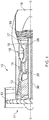
- the combustion chamber 15, as shown more clearly in figure 2 is an annular combustion chamber and comprises a radially inner annular wall structure 40, a radially outer annular wall structure 42 and an upstream end wall structure 44.
- the radially inner annular wall structure 40 comprises a first annular wall 46.
- the radially outer annular wall structure 42 comprises a second annular wall 48.
- the upstream end of the first annular wall 46 is secured to the upstream end wall structure 44 and the upstream end of the second annular wall 48 is secured to the upstream end wall structure 44.
- the upstream end wall structure 44 has a plurality of circumferentially spaced apertures 50 and each aperture 50 has a respective one of a plurality of fuel injectors 52 located therein.
- the fuel injectors 52 are arranged to supply fuel into the annular combustion chamber 15 during operation of the gas turbine engine 10. If the combustion chamber 15 is a rich burn combustion chamber, the first annular wall 46 has one or more dilution apertures 59 to supply dilution air into the annular combustion chamber 15 and the second annular wall 48 has one or more dilution apertures 71 to supply dilution air into the annular combustion chamber 15. If the combustion chamber 15 is a lean burn combustion chamber the first annular wall 46 and the second annular wall 48 do not have dilution apertures.
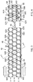
- the first annular wall 46 is shown more clearly in figures 3 and 4 .
- the first annular wall 46 of the combustion chamber 15 is hollow and has a first surface 54 and a second surface 56.
- the first annular wall 46 comprises a plurality of polyhedron shaped chambers 58 defined by a matrix 60 of integral interconnected walls 62 and thus the first annular wall 46 comprises a single, monolithic or unitary, piece.
- the polyhedron shaped chambers 58 are arranged in three layers A, B and C between the first surface 54 and the second surface 56 of the first annular wall 46.
- the walls 62A of the polyhedron shaped chambers 58A in the first layer A define the first surface 54 of the first annular wall 46 of the combustion chamber
- the walls 62B of the polyhedron shaped chambers 58C in the third layer C define the second surface 56 of the first annular wall 46 of the combustion chamber 15.
- Adjacent polyhedron shaped chambers 58 share a common wall.
- the polyhedron shaped chambers 58A, 58B and 58C in each layer A, B and C are interconnected to the polyhedron shaped chambers 58A, 58B and 58C in each adjacent layer A, B and C by apertures extending through the walls of the polyhedron shaped chambers 58 for the flow of coolant D there-between.
- the walls of the polyhedron shaped chambers 58B in the second layer B have apertures 64C extending there-through to supply coolant D into the polyhedron shaped chambers 58C in the third layer C and the walls of the polyhedron shaped chambers 58C in the third layer C have apertures 64D extending there-through to supply coolant D from the polyhedron shaped chambers 58C in the third layer C into the combustion chamber 15.
- the apertures 64A are preferably arranged in the walls of the polyhedron shaped chambers 58A facing in an upstream direction, as shown in figures 3 and 4 , to enable a controlled flow of coolant D into the first layer A of chambers 58A.
- the apertures 64A may be arranged in the walls of the polyhedron shaped chambers 58A facing in a downstream direction.
- the apertures 64B are preferably arranged in the walls of the polyhedron shaped chambers 58A facing in a downstream direction, as shown in figures 3 and 4 , to enable a controlled flow of coolant D from the chambers 58A of first layer A into the chambers 58B in the second layer B.
- the apertures 64B may be arranged in the walls of the polyhedron shaped chambers 58A facing in an upstream direction.
- the apertures 64C are preferably arranged in the walls of the polyhedron shaped chambers 58B facing in an upstream direction and in the walls of the polyhedron shaped chambers 58B facing in a downstream direction, as shown in figures 3 and 4 , to enable a controlled flow of coolant D from the chambers 58B in the second layer B into the chambers 58C in the third layer C.
- the apertures 64C may be arranged only in the walls of the polyhedron shaped chambers 58B facing in a downstream direction or only in the walls of the polyhedron shaped chambers 58B facing in an upstream direction.
- the apertures 64D are arranged in the walls of the polyhedron shaped chambers 58C facing in a downstream direction, as shown in figures 3 and 4 , to enable a controlled flow of coolant D onto the second surface 56 of the first annular wall 46 to form a film of coolant D on the second surface 56 of the first annular wall 46.
- the controlled flow of coolant D may be a turbulent flow of coolant to enhance heat transfer.
- the first surface 54 of the first annular wall 46 is multi-faceted, as shown in figures 3 and 4 , and the facets are defined by the walls of the polyhedron shaped chambers 58A in the first layer A. Some of the facets defined by the walls of the polyhedron shaped chambers 58A in the first layer A face in an upstream direction and some of the facets defined by the walls of the polyhedron shaped chamber 58A in the first layer A face in a downstream direction.
- the facets defined by the walls of the polyhedron shaped chambers 58A facing in an upstream direction have the apertures 64A extending there-through to supply coolant D into the polyhedron shaped chambers 58A in the first layer A.
- the apertures 64A in the facets, or walls, of the polyhedron shaped chambers 58A facing in an upstream direction may have the same cross-sectional area as the facets of the polyhedron shaped chambers 58A such that the facets, or walls, of the polyhedron shaped chambers 58A facing in a downstream direction form scoops to supply coolant D into the polyhedron shaped chambers 58A in the first layer A.
- the scoops provide a total pressure feed of coolant into the first annular wall 46.
- the second surface 56 of the first annular wall 46 is cylindrical, as shown in figures 3 and 4 , and the facets, or walls, of the polyhedron shaped chambers 58C facing in a downstream direction defining the second surface 56 have the apertures 64D extending there-through to supply coolant D from the third layer C in a downstream direction into the combustion chamber 15.
- the apertures 64D are arranged to minimise the exit velocity of the coolant D and reduce mixing between the hot gases in the combustion chamber 15 and the coolant D.
- the apertures 64D may be angled in a downstream direction and the apertures 64D may be circular in cross-section with an axially slotted exit or the apertures 64D may have a fan shaped exit and the fan shaped exit diverges in a direction perpendicular to the downstream direction.
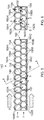
- the flow of coolant D through the first annular wall 46 is shown more clearly in figure 4 .
- the coolant D flows through an aperture 64A in the wall 62A of each polyhedron shaped chamber 58A and into a respective polyhedron shaped chamber 58A.
- the coolant D is then supplied from circumferentially alternate ones of the polyhedron shaped chamber 58A of the first layer A through apertures 64B into two circumferentially adjacent polyhedron shaped chambers 58B in the second layer B.
- the polyhedron shaped chambers 58A' in the first layer A which are positioned circumferentially between the polyhedron shaped chambers 58A which supply coolant to the polyhedron shaped chambers 58B in the second layer B do not have apertures connecting these polyhedron shaped chambers 58A' to polyhedron shaped chambers 58B in the second layer B.
- the polyhedron shaped chambers 58A' thus reduce the weight of the first annular wall 46 but do not allow a flow of coolant.
- the apertures 64A in the polyhedron shaped chambers 58A' allow removal of the metal powder used during manufacture, see below.
- the coolant D is than supplied from each polyhedron shaped chamber 58B in the second layer B into two circumferentially adjacent polyhedron shaped chambers 58C in the third layer C through the apertures 64C.
- the coolant D flowing through the apertures 64C from two circumferentially adjacent polyhedron shaped chambers 58B in the second layer B into a polyhedron shaped chamber 58C in the third layer C comprises jets of coolant which collide, or impinge on each other, to enhance turbulence and heat transfer within the polyhedron shaped chambers 58C in the third layer C.
- the polyhedron shaped chamber 58C in the third layer C may have apertures 64E interconnecting circumferentially adjacent polyhedron shaped chambers 58C to provide additional coolant jets of coolant D.
- the coolant D then flows out of the polyhedron shaped chamber 58C in the third layer C through the apertures 64D and over the second surface 56 of the first annular wall 46 to form a film of coolant D on the second surface 56 of the first annular wall 46.
- the arrangement of figures 3 and 4 provides dendritic cooling of the first annular wall 46.
- the walls, or facets, of the polyhedron shaped chambers 58A form the first surface 54 of the first annular wall 46 and it is to be noted that these walls, or facets, form an undulating surface in both a circumferential and an axial direction and this undulating surface increases the heat transfer from the first surface 54 of the first annular wall 46 into the coolant flowing over the first surface 54 of the first annular wall 46.
- the thickness of the walls of the polyhedron shaped chambers 58A, 58B and 58C is preferably in the range of 0.2 to 2mm, e.g. 0.5 to 1mm, and the distance between the walls of the polyhedron shaped chambers 58A, 58B and 58C is preferably in the range of 1 to 4mm.
- the polyhedron shaped chambers 58 are rhombic dodecahedron shaped chambers and each facet/wall of the rhombic dodecahedron has a rhombic shape and all of the polyhedron shaped chambers 58 have the same shape, the same volume, same dimensions, etc.
- Other polyhedron shaped chambers may be used for example parallelogram sided cuboid shaped chambers, square based pyramid shaped chambers, elongated dodecahedron shaped chambers, truncated dodecahedron shaped chambers or two types of polyhedron shaped chambers, e.g. two types of irregular polyhedron shaped chambers arranged in a Weaire-Phelan structure.
- spherical shaped chambers or spheroidal shaped chambers may be used.
- the apertures 64A may be arranged such that they are positioned at a line of intersection of two adjacent facets of the polyhedron shaped chambers 58A and thus are provided through both of the two adjacent facets.
- the apertures 64D may be arranged such that they are positioned at a line of intersection of two adjacent facets of the polyhedron shaped chambers 58C and thus are provided through both of the two adjacent facets.
- the first annular wall 146 of the combustion chamber 15 is hollow and has a first surface 154 and a second surface 156.
- the first annular wall 146 comprises a plurality of polyhedron shaped chambers 158 defined by a matrix 160 of integral interconnected walls 162 and thus the first annular wall 146 comprises a single, monolithic or unitary, piece.
- the polyhedron shaped chambers 158 are arranged in two layers E and F between the first surface 154 and the second surface 156 of the first annular wall 146.
- the walls 162A of the polyhedron shaped chambers 158A in the first layer E define the first surface 154 of the first annular wall 146 of the combustion chamber
- the walls 162B of the polyhedron shaped chambers 158B in the second layer F define the second surface 156 of the first annular wall 146 of the combustion chamber 15.
- Adjacent polyhedron shaped chambers 158 share a common wall.
- the polyhedron shaped chambers 158A and 158B in each layer E and F are interconnected to the polyhedron shaped chambers 158A and 158B in each adjacent layer E and F by apertures extending through the walls of the polyhedron shaped chambers 58 for the flow of coolant D there-between.
- the first annular wall 146 is substantially the same as the first annular wall 46 but the first annular wall 146 only has two layers E and F of polyhedron shaped chambers 158A and 158B compared to three layers A, B and C of polyhedron shaped chambers 58A, 58B and 58C for the first annular wall 46.
- the flow of coolant D through the first annular wall 146 is shown more clearly in figure 6 .
- the coolant D flows through an aperture 164A in the wall 162A of each polyhedron shaped chamber 158A and into a respective polyhedron shaped chamber 158A.
- the coolant D is then supplied from circumferentially alternate ones of the polyhedron shaped chamber 158A of the first layer E through apertures 164B into two circumferentially adjacent polyhedron shaped chambers 158B in the second layer F.
- the polyhedron shaped chambers 158A' in the first layer E which are positioned circumferentially between the polyhedron shaped chambers 158A which supply coolant to the polyhedron shaped chambers 158B in the second layer F do not have apertures connecting these polyhedron shaped chambers 158A' to polyhedron shaped chambers 158B in the second layer F.
- the polyhedron shaped chambers 158A' thus reduce the weight of the first annular wall 146 but do not allow a flow of coolant.
- the apertures 164A in the polyhedron shaped chambers 158A' allow removal of the metal powder used during manufacture, see below.
- the coolant D then flows out of the polyhedron shaped chamber 158B in the second layer C through the apertures 164C and over the second surface 156 of the first annular wall 146 to form a film of coolant D on the second surface 156 of the first annular wall 146.
- the apertures 164C are arranged to minimise the exit velocity of the coolant D and reduce mixing between the hot gases in the combustion chamber 15 and the coolant D.
- the apertures 164C may be angled in a downstream direction and the apertures 164C may be circular in cross-section with an axially slotted exit or the apertures 164C may have a fan shaped exit and the fan shaped exit diverges in a direction perpendicular to the downstream direction.
- the arrangement of figures 5 and 6 provides dendritic cooling of the first annular wall 146.
- the polyhedron shaped chambers 158 are rhombic dodecahedron shaped chambers and each facet/wall of the rhombic dodecahedron has a rhombic shape and all of the polyhedron shaped chambers 158 have the same shape, the same volume, same dimensions, etc.
- Other polyhedron shaped chambers may be used for example parallelogram sided cuboid shaped chambers, square based pyramid shaped chambers, elongated dodecahedron shaped chambers, truncated dodecahedron shaped chambers or two types of polyhedron shaped chambers, e.g. two types of irregular polyhedron shaped chambers arranged in a Weaire-Phelan structure.
- spherical shaped chambers or spheroidal shaped chambers may be used.
- the apertures 164A may be arranged such that they are positioned at a line of intersection of two adjacent facets of the polyhedron shaped chambers 158A and thus are provided through both of the two adjacent facets.
- the apertures 164B may be arranged such that they are positioned at a line of intersection of two adjacent facets of the polyhedron shaped chambers 158B and thus are provided through both of the two adjacent facets.
- the first annular wall 246 of the radially inner annular wall structure 240 is shown more clearly in figure 7 .
- the first annular wall 246 of the combustion chamber 15 is hollow and has a first surface 254 and a second surface 256.
- the first annular wall 246 comprises a plurality of polyhedron shaped chambers 258 defined by a matrix 260 of integral interconnected walls 262 and thus the first annular wall 246 comprises a single, monolithic or unitary, piece.
- the polyhedron shaped chambers 258 are arranged in four layers G, H, I and J between the first surface 254 and the second surface 256 of the first annular wall 246.
- the walls 262A of the polyhedron shaped chambers 258A in the first layer E define the first surface 154 of the first annular wall 146 of the combustion chamber
- the walls 262B of the polyhedron shaped chambers 258D in the fourth layer F define the second surface 256 of the first annular wall 246 of the combustion chamber 15.
- Adjacent polyhedron shaped chambers 258 share a common wall.
- the polyhedron shaped chambers 258A, 258B, 258C and 258D in each layer G, H, I and J are interconnected to the polyhedron shaped chambers 258A, 258B, 258C and 258D in each adjacent layer G, H, I and J by apertures extending through the walls of the polyhedron shaped chambers 158 for the flow of coolant D there-between.
- the first annular wall 246 is substantially the same as the same as the first annular wall 46 but the first annular wall 246 has four layers G, H, I and J of polyhedron shaped chambers 258A, 258B, 258C and 258D compared to three layers A, B and C of polyhedron shaped chambers 58A, 58B and 58C for the first annular wall 46.
- the polyhedron shaped chambers 258 are rhombic dodecahedron shaped chambers and each facet/wall of the rhombic dodecahedron has a rhombic shape and all of the polyhedron shaped chambers 258 have the same shape, the same volume, same dimensions, etc.
- Other polyhedron shaped chambers may be used for example parallelogram sided cuboid shaped chambers, square based pyramid shaped chambers, elongated dodecahedron shaped chambers, truncated dodecahedron shaped chambers or two types of polyhedron shaped chambers, e.g. two types of irregular polyhedron shaped chambers arranged in a Weaire-Phelan structure.
- spherical shaped chambers or spheroidal shaped chambers may be used.
- the first surface 254 of the first annular wall 246 is multi-faceted, as shown in figure 7 , and the facets are defined by the walls of the polyhedron shaped chambers 258A in the first layer G. Some of the facets defined by the walls of the polyhedron shaped chambers 258A in the first layer G face in an upstream direction and some of the facets defined by the walls of the polyhedron shaped chamber 258A in the first layer G face in a downstream direction.
- the facets defined by the walls of the polyhedron shaped chambers 258A facing in an upstream direction have the apertures 264A extending there-through to supply coolant D into the polyhedron shaped chambers 258A in the first layer G.
- the apertures 264A in the facets, or walls, of the polyhedron shaped chambers 258A facing in an upstream direction have the same cross-sectional area as the facets of the polyhedron shaped chambers 258A such that the facets, or walls, of the polyhedron shaped chambers 258A facing in a downstream direction form scoops to supply coolant D into the polyhedron shaped chambers 258A in the first layer A.
- the scoops provide a total pressure feed of coolant into the first annular wall 246.
- the apertures 264A in the facets facing in an upstream direction may have a smaller cross-sectional area than the facets of the polyhedrons shaped chambers 258A.
- the apertures 264D in the facets, or walls, of the polyhedron shaped chambers 258D facing in a downstream direction have the same cross-sectional area as the facets of the polyhedron shaped chambers 258D such that the facets, or walls, of the polyhedron shaped chambers 258D facing in a downstream direction form outlets to supply coolant D from the polyhedron shaped chambers 258D in the fourth layer D over the second surface 256 of the first annular wall 246.
- the apertures 264D in the facets facing in a downstream direction may have a smaller cross-sectional area than the facets of the polyhedrons shaped chambers 258D.
- the apertures 264D may be arranged to minimise the exit velocity of the coolant D and reduce mixing between the hot gases in the combustion chamber 15 and the coolant D.
- the apertures 264D may be angled in a downstream direction and the apertures 264D may be circular in cross-section with an axially slotted exit or the apertures 264D may have a fan shaped exit and the fan shaped exit diverges in a direction perpendicular to the downstream direction.
- the apertures 264A may be arranged such that they are positioned at a line of intersection of two adjacent facets of the polyhedron shaped chambers 258A and thus are provided through both of the two adjacent facets.
- the apertures 264D may be arranged such that they are positioned at a line of intersection of two adjacent facets of the polyhedron shaped chambers 258D and thus are provided through both of the two adjacent facets.
- the flow of coolant D through the first annular wall 246 may be similar to that shown with respect figures 5 and 6 .
- FIG. 7 Another possible flow of coolant D through the first annular wall 246 is shown in figure 7 .
- the flow of coolant D through the first annular wall 246 follows a tortuous flow path in which the coolant D flows from a polyhedron shaped chamber 258A in the first layer G through intervening polyhedron shaped chamber 258B, 258C in the second and third layers H, I to a polyhedron shaped chamber 258D in the fourth layer J.
- the coolant D then flows from the polyhedron shaped chamber 258D in the fourth layer J circumferentially to an adjacent polyhedron shaped chamber 258D and then through intervening polyhedron shaped chamber 258C, 258B in the third and second layers I, H to a polyhedron shaped chamber 258A in the first layer G.
- the coolant D then flows from the polyhedron shaped chamber 258A in the first layer G circumferentially to an adjacent polyhedron shaped chamber 258A and then through intervening polyhedron shaped chamber 258B, 258C in the second and third layers H, I to a polyhedron shaped chamber 258D in the fourth layer J and then out of that polyhedron shaped chamber 258D in the fourth layer J and over the surface 256 of the first annular wall 246
- the first and/or second annular wall may comprise two, three, four or more layers of polyhedron shaped chambers.
- the first surface of the first and/or second annular wall may be cylindrical.
- the first surface of the first and/or second annular wall may have at least one rib extending there-from in a direction away from the second surface, e.g. radially away from the first surface of the first or second annular wall, to increase heat transfer from the first surface of the first and/or second annular wall to the coolant flowing over the first surface.
- the at least one rib may extend in a circumferential direction or in an axial direction.
- the at least one rib may extend in the direction of build by the manufacturing process, e.g. DLD build direction.
- the first surface of the first and/or second annular wall may be corrugated.
- the apertures in the facets facing in an upstream direction may have the same cross-sectional area as the facets such that the facets facing in a downstream direction form scoops to supply coolant into the first layer.
- the apertures in the downstream walls of the polyhedron shaped chambers defining the second surface may have the same cross-sectional area as the downstream walls of the polyhedron shaped chambers.
- At least one of the polyhedron shaped chambers may have one or more ribs extending from at least one of the walls of the at least one of the polyhedron shaped chambers into the respective polyhedron shaped chamber to increase heat transfer from the at least one of the walls of the polyhedron shaped chamber to the coolant flowing through the polyhedron shaped chamber.
- a plurality of the polyhedron shaped chambers may have one or more ribs extending from at least one of the walls of the polyhedron shaped chambers into the respective polyhedron shaped chambers to increase heat transfer from the at least one of the walls of the polyhedron shaped chambers to the coolant flowing through the polyhedron shaped chambers.
- the at least one rib extending from the at least one of the walls of the at least one of the polyhedron shaped chambers extends axially of the first and/or second annular wall.
- the at least one rib may extend in the direction of build by the manufacturing process, e.g. DLD build direction.
- the combustion chamber wall may be formed from a nickel base superalloy, a cobalt base superalloy or an iron base superalloy.
- a thermal barrier coating may be provided on the second surface of the combustion chamber wall.
- the thermal barrier coating may comprise a ceramic material.
- the ceramic material may comprise zirconia or stabilised zirconia.
- the thermal barrier coating may be provided on the second surface of the combustion chamber wall by plasma spraying, physical vapour deposition, e.g. electron beam physical vapour deposition, or chemical vapour deposition.
- a bond coating may be provided on the second surface of the combustion chamber wall before the thermal barrier coating.
- the bond coating may comprise a MCrAlY coating, where M is one or more of nickel, cobalt and iron, or an aluminide coating, e.g. a simple aluminide, a chromium aluminide, a platinum aluminide, platinum chromium aluminide or a silicide aluminide.
- the axial ends of the first and/or second annular wall 46, 48 are solid and there is a transition from the polyhedron shaped chambers to the solid ends.
- the axial ends, the upstream and downstream ends, of the first and/or second annular wall 46, 48 are joined to the upstream end wall structure 44 and to a nozzle guide vane structure (not shown).
- the axial ends of the first and/or second annular wall 46, 48 may be provided with a tongue or a groove to locate in or on a groove or a tongue of the upstream end wall structure 42 and the nozzle guide vane structure and then the axial ends may be welded, brazed or bonded to the upstream end wall structure 42 and the nozzle guide vane structure.
- first and/or second walls 46, 48 may be joined to the upstream end wall structure 42 and the nozzle guide vane structure by other suitable joints.
- the tongue and groove arrangements form seals to minimise leakage of hot gases from the combustion chamber 15 and also controls the flow of coolant into the combustion chamber 15.
- the first annular wall 46 and/or second annular wall 48 of the combustion chamber 15 is manufactured by an additive manufacturing process, for example selective laser melting, direct laser deposition, powder bed fusion, shaped metal deposition.
- Powder bed fusion uses a laser beam or an electron beam to melt and fuse powder particles together to build up an article layer by layer from powder material, e.g. powder metal, by moving the laser beam, or electron beam, in a predetermined pattern, or path, across sequentially deposited layers of powder material.
- Shaped metal deposition uses a welding torch, a laser beam or an electron beam torch to melt and fuse material together to build up an article layer by layer from powder material, e.g.
- the first annular wall 46 and/or the second annular wall 48 may be manufactured by any suitable additive layer manufacturing technique.
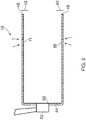
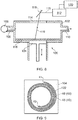
- the first annular wall 46 and/or second annular wall 48 of the combustion chamber 15 is manufactured for example using selective laser melting or powder bed fusion using an apparatus shown in Figure 8 .
- the apparatus 100 comprises a sealed chamber 102, which has a retractable platform 104.
- a pump 106 is provided to supply an inert gas, argon or nitrogen, through a pipe 108 into the chamber 102 and gas is extracted from the chamber 102 via a pipe 110.
- a laser 112 e.g. an infrared laser, is provided to direct a laser beam 119 through a window 114 in the chamber 102.
- a controller 120 has a CAD definition of the shape and features of the first annular wall 46 and/or second annular wall 48 of the combustion chamber 15 and the laser 112 is moved under the control of the controller 120.
- the controller 120 has a CAD definition of the shape and features of the radially inner annular wall structure 40 and/or the radially outer annular wall structure 42 of the combustion chamber 15 and the laser 112 is moved under the control of the controller 120.
- the radially inner annular wall structure 40 is a unitary structure comprising the first annular wall 46 and the radially outer wall structure 42 is a unitary structure comprising the second annular wall 48.
- the first annular wall 46 is hollow and comprises a first surface 54 and a second surface 56 and the first annular wall 46 comprises a plurality of polyhedron shaped chambers 58 defined by a matrix of integral interconnected walls 62 and the polyhedron shaped chambers 58 are arranged in at least two layers between the first surface 54 and the second surface 56.
- the second annular wall 48 is hollow and comprises a first surface and a second surface and the second annular wall 48 comprises a plurality of polyhedron shaped chambers defined by a matrix of integral interconnected walls and the polyhedron shaped chambers are arranged in at least two layers between the first surface and the second surface.
- the first annular wall 46 and/or second annular wall 48 is manufactured by placing a first layer 116 of a suitable metal, or alloy, powder, on the retractable platform 104 in the sealed chamber 102.
- the laser beam 119 is scanned across the layer of metal powder 116 in a predetermined pattern to form a first layer of the first annular wall 46 and/or second annular wall 48 by bodily moving the laser 112 appropriate distances in perpendicular X and Y directions or by deflecting the laser beam 119 off a movable mirror 118.
- the laser beam 119 melts and fuses or sinters the metal powder where it strikes the layer of metal powder 116.
- the platform 104 is retracted one increment outwards from the chamber 102 and the laser beam 119 is scanned across the layer of metal powder in a further predetermined pattern to form a second layer of the first annular wall 46 and/or third annular wall 48 respectively.
- the laser beam 119 melts and fuses or sinters the metal powder where it strikes the second layer of metal powder 116 and bonds, fuses or sinters the second layer of the first annular wall 46 and/or second annular wall 48 to the first layer of the first annular wall 46 and/or second annular wall 48 respectively.
- the process of placing layers of metal powder, retracting the platform 104 and scanning the laser beam 119 across the layer of metal powder in a predetermined pattern to fuse and sinter the metal powder in each layer and to bond each layer to the previously deposited layer is repeated a sufficient number of times to build the first annular wall 46 and/or second annular wall 48 layer by layer from one axial end to the opposite axial end.
- the predetermined pattern of scanning of the laser beam 119 for each layer is determined by the CAD model of the first annular wall 46 and/or second annular wall 48.
- first annular wall 46 and/or second annular wall 48 of the combustion chamber 15 is an annular wall, but the present disclosure manufactures the first annular wall 46 and/or second annular wall 48 by moving the laser beam 119 in a predetermined spiral pathway 122, as shown in Figure 9 , and thus the metal powder in each layer is melted and fused or sintered to form a spiral to produce each layer of a first spiral wall 45 and/or a second spiral wall 49.
- a number of the layers of the first spiral wall 45 and/or the second spiral wall 49 are solid to define an axial end of the first annular wall 46 and/or second annular wall 48. Then some of the subsequent layers of the first spiral wall 45 and/or second spiral wall 49 have one or more regions where the metal powder in that particular layer of the spiral 122 is not melted and fused or sintered.
- the regions of the subsequent layers where the metal powder is melted and fused or sintered defines the matrix of interconnected walls 62 and in particular defines or forms the walls of the polyhedron shaped chambers 58.
- the regions of the subsequent layers of the first spiral wall 46 and/or the second spiral wall 49 where the metal powder is not melted and fused or sintered are primarily the polyhedron shaped chambers 58.
- apertures 64 are apertures 64A in the first surface 54 of the first annular wall 46 and/or second annular wall 48 to provide coolant into the polyhedron shaped chambers 58A in the first layer A in the first annular wall 46 and/or second annular wall 48 respectively.
- apertures 64 are apertures 64D in the second surface 56 of the first annular wall 46 and/or second annular wall 48 to enable coolant to flow out of the polyhedron shaped chambers 58C in the third layer C in the first annular wall 46 and/or second annular wall 48 respectively and onto the second surface 56 of the first annular wall 46 and/or second annular wall 48.
- the remainder of the apertures 64 are apertures 64B and 64C extending between the polyhedron shaped chambers 58 in the layers A, B and C of the first annular wall 46 and/or second annular wall 48.
- apertures may be dilution apertures 59 or 71 for the first annular wall 46 and second annular wall 48, which extend completely through the first annular wall 46 and the second annular wall 48, respectively to provide dilution air into the annular combustion chamber 15.
- a number of the layers of the first spiral wall 45 and/or second spiral wall 49 are solid to define an opposite axial end of the first annular wall 46 and/or second annular wall 48.
- the first spiral wall 45 and/or second spiral wall 49 is built up layer by layer by melting and fusing or sintering the metal powder.
- the un-fused, or un-sintered, metal powder is removed in particular from the regions forming the polyhedron shaped chambers 58 and the apertures 64, 59 and 71 in the first spiral wall 45 and/or second spiral wall 49.
- the completed first spiral wall 45 and/or the second spiral wall 49 is then removed from the apparatus 100.
- the completed first spiral wall 45 and/or the second spiral wall 49 is then rolled out to form a ring, e.g. a spilt ring, and the ends K1 and K2 of what was the first spiral wall 45 or second spiral wall 49 are abutted and joined together in an end K1 to end K2 manner as shown in Figure 11 to form the first annular wall 46 and/or the second annular wall 48.
- the ends K1 and K2 of the first spiral wall 45 or second spiral wall 49 are joined together by welding, bonding, brazing, bolting or other suitable joining techniques to form the first annular wall 46 and/or the second annular wall 48.
- the ends K1 and K2 of the first spiral wall 45 or second spiral wall 49 may be solid metal and the ends K1 and K2 of the first spiral wall 45 or second spiral wall 49 may be provided with a tongue or a groove at the end K1 to locate in or on a groove or a tongue of the opposite end K2 of the first spiral wall 45 or second spiral wall 49, as shown in Figure 12 .
- the tongue and groove arrangements form seals to minimise leakage of hot gases from the combustion chamber.
- the ends K1 and K2 of the first spiral wall 45 or second spiral wall 49 may be welded, brazed or bonded to the opposite end of the first spiral wall 45 or second spiral wall 49.
- the ends K1 and K2 of the first spiral wall 45 or second spiral wall 49 may be joined together by other suitable joints.
- the ends K1 and K2 of the first spiral wall 45 or second spiral wall 49 have layers of polyhedron shaped chambers 58 and the ends K1 and K2 of the first spiral wall 45 or second spiral wall 49 are provided with a tongue or a groove at the end K2 to locate in or on a groove or a tongue at the opposite end K1 of the first and/or second spiral wall 45, 49 as shown in Figure 13 .
- the tongue and groove arrangements form seals to minimise leakage of hot gases from the combustion chamber.
- the polyhedron shaped chambers 58 in the layers at the ends K1 and K2 are arranged to align with the polyhedron shaped chambers 58 in the layers at the opposite end K1 and K2 of the first spiral wall 45 or second spiral wall 49 to maintain the porosity of the first and/or second annular wall 46, 48 and to allow the coolant to flow through the first and/or second annular wall 46, 48 at the joint between the, or each pair of adjacent segments.
- the ends K1 and K2 are joined by fasteners, e.g. nuts and bolts extending through flanges provided on the ends K1 and K2, by welding or by brazing.
- a standard powder bed fusing apparatus has base dimensions of 250mm by 250mm and the first and second annular walls 46 and 48 of the annular combustion chamber 15 have diameters much greater than 250mm for example 1m.
- the first annular wall 46 and the second annular wall 48 have an inner diameter and an outer diameter.
- the first annular wall 46 and the second annular wall 48 in this example are tubular and the inner diameter of both of the annular walls 46 and 48 is substantially constant along the length of the annular walls 46 and 48, except for flanges, bosses etc, and the outer diameter of both of the annular walls 46 and 48 is substantially constant along the length of the annular walls 46 and 48, except for flanges, bosses etc.
- the annular walls 46 and 48 may be frusto-conical and the inner diameter of both of the annular walls 46 and 48 increases from a first end of the annular wall 46 and 48 to a second end of the annular wall 46 and 48 and the outer diameter of both of the annular walls 46 and 48 increases from the first end of the annular wall 46 and 48 to the second end of the annular wall 46 and 48.
- the inner diameter and the outer diameter of the annular wall 46 and 48 may increase gradually from the first end to the second end of the annular wall 46 and 48, except for flanges, bosses etc.
- the inner diameter and the outer diameter of the annular wall 46 and 48 may increase constantly, or in a stepped manner, from the first end to the second end of the annular wall 46 and 48. It may be possible that the first annular wall 46 is tubular and the second annular wall 48 is frusto-conical or visa-versa.
- the manufacturing process for a tubular wall involves moving the laser beam along a plurality of spiral pathways, one for each layer of powder metal, and that all the spiral pathways have the same shape and the same length.
- the manufacturing process for a frustoconical wall is substantially the same as that for a tubular wall except the spiral pathway along which the laser beam is moved is different for each layer of powder metal and in particular the spiral pathway has a different length for each layer of powder metal and so that the spiral pathways progressively increase or decrease in length as the layers of powder metal are deposited.
- An advantage of the manufacturing process of the present disclosure is that it enables the manufacture of a large diameter first annular wall 46 and/or second annular wall 48 within the confines of a powder bed fusion apparatus which has dimensions less than the diameter of the first annular wall 46 and/or second annular wall 48.
- a further advantage of the manufacturing process of the present disclosure is that it eliminates the need for forging and turning of a metal billet to produce the first annular wall 46 and/or second annular wall 48 and eliminates the need to drill by machining, electrochemical machining, electro discharge machining, laser machining etc the dilution apertures, cooling apertures and mounting apertures through either or both of these annular walls. It eliminates the need for casting large numbers of tiles and the need to drill by machining, electrochemical machining, electro discharge machining or laser machining the cooling apertures. Another advantage is that it obviates the need to assemble a number of parts.
- the radially inner annular wall structure 40 e.g. the first annular wall 46
- the radially outer annular wall structure 42 e.g. the second annular wall 48
- the radially inner annular wall structure 40 e.g. the first annular wall 46
- the radially outer annular wall structure 42 e.g. the second annular wall 48
- the ribs extending from the walls of the polyhedron shaped chambers 58 and within the polyhedron shaped chambers 58 extend axially with respect to the first and/or second annular wall 46 and 48 and are produced easily as the first and/or second annular walls 46 and 48 by building them up layer by layer and thus the ribs extending from the walls of the polyhedron are arranged to extend in the direction of build of the first and/or second annular walls 46 and 48.
- the first and/or second annular wall 46 and 48 are built up layer by layer in the axial direction of the first and second annular walls 46 and 48.
- there are no horizontal facets, or walls, for the polyhedron shaped chambers and all the walls, or facets, of the polyhedron shaped chambers are at an angle of 45° to the horizontal plane or at an angle of 45° the direction of build.
- truncated dodecahedron shaped chambers there are no horizontal facets, or walls, for the polyhedron shaped chambers and the walls, or facets, of the polyhedron shaped chambers are either at an angle of 45° or 30° to the horizontal plane or at angle of 45° or 60° to the build direction.
- facets, or walls, of the polyhedron shaped chambers arranged at an angle of 30° to the horizontal plane or 60° to the build direction the internal surface may be arched to make the manufacturing easier.
- first and/or second annular walls 46 and 48 in circumferential segments using the same apparatus as shown in figure 8 .
- the segments are again built up layer by layer in an axial direction and then the segments are joined together by welding, bonding, brazing, bolting or other suitable joining techniques to form the first annular wall 46 and/or the second annular wall 48.
- the circumferential ends of the segments may be solid metal and the circumferential ends of the segments of the first and/or second annular wall 46, 48 may be provided with a tongue or a groove to locate in or on a groove or a tongue of an adjacent segment of the first and/or second annular wall 46, 48.
- the tongue and groove arrangements form seals between the circumferential ends of adjacent segments to minimise leakage of hot gases from the combustion chamber.
- the circumferential ends of the segments of the first and/or second walls 46, 48 may be welded, brazed or bonded to an adjacent segment of the first and/or second wall 46, 48.
- the circumferential ends of the segments of the first and/or second walls 46, 48 may be joined to an adjacent segment of the first and/or second wall 46, 48 by other suitable joints.
- the circumferential ends of the segments may have layers of polyhedron shaped chambers 58 and the circumferential ends of the segments of the first and/or second annular wall 46, 48 may be provided with a tongue or a groove to locate in or on a groove or a tongue of an adjacent segment of the first and/or second annular wall 46, 48.
- the tongue and groove arrangements form seals between the circumferential ends of adjacent segments to minimise leakage of hot gases from the combustion chamber.
- the polyhedron shaped chambers 58 in the layers at a circumferential end of one segment are arranged to align with the polyhedron shaped chambers 58 in the layers at the circumferential end of the adjacent segment to maintain the porosity of the first and/or second annular wall 46, 48 and to allow the coolant to flow through the first and/or second annular wall 46, 48 at the joint between the, or each pair of adjacent segments.
- the segments are joined by fasteners, e.g. nuts and bolts extending through flanges provided on the ends of the segments, by welding or by brazing.
- the first annular wall 146 of the radially inner annular wall structure 140 and/or the first annular wall 246 of the radially inner annular wall 240 may be manufactured using the apparatus and methods described with reference to figures 8 to 13 .
- Figures 14 and 15 show a further first annular wall 346 of the radially inner annular wall structure 340.
- the first annular wall 346 comprises a plurality of polyhedron shaped chambers 358 defined by a matrix 360 of integral interconnected walls 362 and thus the first annular wall 346 comprises a single, monolithic or unitary, piece.
- the first annular wall 346 of a combustion chamber wall comprises elongated dodecahedron shaped chambers 358 in which the dodecahedrons are elongated in an axial direction of the radially inner annular wall 340.
- the elongated dodecahedron shaped chambers have four hexagonal shaped facets/walls and eight rhombic facets/walls.
- the first annular wall 346 of the combustion chamber wall also comprises some polyhedron shaped chambers 358D which are half of an elongated dodecahedron shaped chamber 358.
- every third polyhedron shaped chamber 358A in the first layer has an aperture 364A for the supply of coolant and the polyhedron shaped chambers 358A' in the first layer are not supplied with coolant.
- Each polyhedron shaped chamber 358A in the first layer has apertures to supply coolant into two circumferentially adjacent polyhedron shaped chambers 358B in the second layer and every third polyhedron shaped chambers 358B' in the second layer is not supplied with coolant.
- Each polyhedron shaped chamber 358B in the second layer has apertures to supply coolant into two circumferentially adjacent polyhedron shaped chambers 358C in the third layer and each polyhedron shaped chamber 358C in the third layer has apertures to supply coolant into a respective half polyhedron shaped chamber 358C' in the third layer.
- Each half polyhedron shaped chamber 358C' in the third layer has one or more apertures 364E to supply the coolant over the inner surface 356 of the radially inner annular wall 340.
- the polyhedron shaped chambers 358C are arranged in rows of circumferentially adjacent polyhedron shaped chambers 358C and the half polyhedron shaped chambers 358C' are arranged in rows of circumferentially adjacent half polyhedron shaped chambers 358C'.
- the rows of circumferentially adjacent polyhedron shaped chambers 358C are arranged axially alternately with rows of circumferentially adjacent half polyhedron shaped chambers 358C'.
- polyhedron shaped chambers 358A and 358A' are arranged in rows of circumferentially adjacent polyhedron shaped chambers 358A, 358A' and each row of circumferentially adjacent polyhedron shaped chambers 358A, 358A' is arranged radially adjacent a corresponding row of circumferentially adjacent polyhedron shaped chambers 358C.
- each aperture 364E overlaps two circumferentially adjacent half polyhedron shaped chambers 358C' and thus each aperture 364E is supplied with coolant D from two half polyhedron shaped chamber 358C' or each half polyhedron shaped chamber 358C' has two circumferentially spaced apertures 364E.
- each half polyhedron shaped chamber 358C' may have a single aperture located circumferentially at the centre of the half polyhedron shaped chamber 358C' or at another suitable position.
- Each row of polyhedron shaped chambers 358A and 358A' is spaced axially from the next row of polyhedron shaped chambers 358A and 358A' and the intervening axial space provides a convoluted outer surface for the first annular wall 346 and provides enhanced heat transfer from the first annular wall 346 to the coolant flowing over the first annular wall 346.
- the apertures 364A provide a total pressure feed of coolant into the first annular wall 346.
- the first annular wall 346 of the radially inner annular wall structure 340 may be manufactured using the apparatus and methods described with reference to figures 8 to 13 .
- the first annular wall 446 of the combustion chamber 15 is hollow and has a first surface 454 and a second surface 456.
- the first annular wall 446 comprises a plurality of spherical shaped chambers 458 defined by a matrix 460 of integral interconnected walls 462 and thus the first annular wall 446 comprises a single, monolithic or unitary, piece.
- the spherical shaped chambers 458 are arranged in three layers A, B and C between the first surface 454 and the second surface 456 of the first annular wall 446.
- the walls 462A of the spherical shaped chambers 458A in the first layer A define the first surface 454 of the first annular wall 446 of the combustion chamber
- the walls 462B of the spherical shaped chambers 458C in the third layer C define the second surface 456 of the first annular wall 446 of the combustion chamber 15.
- Adjacent spherical shaped chambers 58 share a common wall.
- the spherical shaped chambers 458A, 458B and 458C in each layer A, B and C are interconnected to the spherical shaped chambers 458A, 458B and 458C in each adjacent layer A, B and C by apertures extending through the walls of the spherical shaped chambers 458 for the flow of coolant D there-between.
- the walls of the spherical shaped chambers 458A in the first layer A have apertures 464A extending there-through to supply coolant D into the spherical shaped chamber 458A in the first layer A.
- the walls of the spherical shaped chambers 458A in the first layer A have apertures 464B extending there-through to supply coolant D into the spherical shaped chambers 458B in the second layer B.
- the walls of the spherical shaped chambers 458B in the second layer B have apertures 464C extending there-through to supply coolant D into the spherical shaped chambers 458C in the third layer C and the walls of the spherical shaped chambers 458C in the third layer C have apertures 464D extending there-through to supply coolant D from the spherical shaped chambers 458C in the third layer C into the combustion chamber 15.
- the apertures 464A are preferably arranged in the portions of the walls of the spherical shaped chambers 58A facing in an upstream direction, as shown in figure 16 , to enable a controlled flow of coolant D into the first layer A of chambers 458A.
- the apertures 464A may be arranged in the portions of the walls of the spherical shaped chambers 458A facing in a downstream direction.
- the apertures 464B are preferably arranged in the walls of the spherical shaped chambers 458A facing in a downstream direction, as shown in figure 16 , to enable a controlled flow of coolant D from the chambers 458A of first layer A into the chambers 458B in the second layer B.
- the apertures 464B may be arranged in the walls of the spherical shaped chambers 458A facing in an upstream direction.
- the apertures 464C are preferably arranged in the walls of the spherical shaped chambers 458B facing in an upstream direction and in the walls of the spherical shaped chambers 458B facing in a downstream direction, as shown in figure 16 , to enable a controlled flow of coolant D from the chambers 458B in the second layer B into the chambers 458C in the third layer C.
- the apertures 464C may be arranged only in the walls of the spherical shaped chambers 58B facing in a downstream direction or only in the walls of the spherical shaped chambers 58B facing in an upstream direction.
- the apertures 464D are arranged in the walls of the spherical shaped chambers 458C facing in a downstream direction, as shown in figure 16 , to enable a controlled flow of coolant D onto the second surface 456 of the first annular wall 446 to form a film of coolant D on the second surface 456 of the first annular wall 446.
- the controlled flow of coolant D may be a turbulent flow of coolant to enhance heat transfer.
- the first annular wall 446 of the radially inner annular wall structure 440 may also be manufactured using the apparatus and methods described with reference to figures 8 to 13 .
- the centres of the polyhedron shaped chambers in each layer are spaced laterally, radially, from the centres of the polyhedron shaped chambers in the, or each, adjacent layer and the lateral, radial, extremities of the polyhedron shaped chamber in each layer are spaced laterally, radially, from the centres of the polyhedron shaped chambers in the, or each, adjacent layer.
- the centres of the polyhedron shaped chambers in each layer are spaced laterally, radially, from the centres of the polyhedron shaped chambers in the, or each, adjacent layer and the lateral, radial, extremities of the polyhedron shaped chamber in each layer are aligned laterally, radially, with the centres of the polyhedron shaped chambers in the, or each, adjacent layer.
- the polyhedron shaped chambers in each layer are immediately adjacent longitudinally, axially, to another polyhedron shaped chamber in that layer.
- the polyhedron shaped chambers in some of the layers are not immediately adjacent longitudinally, axially, to another polyhedron shaped chamber in that layer but have polyhedron shaped chambers from one or more adjacent layers longitudinally, axially, there-between.
- the coolant used to cool the combustion chamber wall may be air.
- the air may be supplied from a compressor, e.g. the high pressure compressor, of the gas turbine engine
- the combustion chamber may be a gas turbine engine combustion chamber.
- the combustion chamber may be a tubular combustion chamber or an annular combustion chamber.
- the polyhedron shaped chambers are arranged in a regular structure are tessellated and are arranged to provide a flexible, porous, first and/or second annular wall.
- the polyhedrons shaped chambers may be arranged in a number of arrangements to optimise heat transfer distribution through the thickness of the first and/or second annular wall and simultaneously match the pressure loss, or local mass flow, of the coolant through the first and/or second annular wall. These arrangements may be dendritic networks or ducted networks and contain impingement jets and combined impingement jets.
- the apertures linking the polyhedron shaped chambers may be on each adjacent face, or wall, or on selected faces, walls, of the polyhedron shaped chambers to change the direction of the flow of coolant to increase impingement cooling/heat transfer.
- the apertures linking the polyhedron shaped chambers are provided with controlled geometric and effective cross-sectional areas to provide the correct level of overall porosity for the required pressure drop across the first and/or second annular wall.
- the apertures on the first surface of the first and/or second annular wall and the throughout the first and/or second annular wall are preferably dimensioned to maximise heat transfer throughout the thickness of the first and/or second annular wall and this may include arranging to extract more heat across the regions with higher temperature gradients, e.g.
- the layer of polyhedron shaped chambers forming the second surface of the first and/or second annular wall.
- the polyhedron shaped chambers provide the first and/or second annular wall with increased mechanical strength and increased stiffness for a given weight of material.
- the mechanical properties, strength and stiffness may be increased by thickness of the walls defining the polyhedron shaped chambers and/or by increasing the number of layers of polyhedron shaped chambers and/or by increasing the overall thickness of the wall.
- the volume, or dimensions, of the polyhedron shaped chambers in different layers may be different, for example an elongated dodecahedron shaped chamber is easily adjustable by adjusting the length of elongation of the elongated dodecahedron and the length of elongation is arranged in the radial direction of the first and/or second annular wall or the axial direction of the first and/or second annular wall.
- the polyhedron shaped chambers provide the first and/or second annular wall with the ability to damp combustion chamber noise, combustion chamber rumble, combustion chamber resonant frequencies or combustion chamber instabilities by adjusting the volume, increasing the volume, of the polyhedron shaped chambers in the layer of polyhedron shaped chambers forming the second surface of the first and/or second annular wall.
- elongated dodecahedron shaped chambers are useful to alter heat transfer through each layer of elongated dodecahedron shaped chambers. This may be achieved by adjusting the cell elongation to enhance the coolant impingement and modify the distribution of the pressure loss through the wall.
- the elongated dodecahedron shaped chambers are preferred because it is possible the elongated portions with different lengths to produce different volumes of the polyhedron shaped chambers in one or more of the layers, e.g. each layer could have a different length for the elongated portion.
Landscapes
- Engineering & Computer Science (AREA)
- Mechanical Engineering (AREA)
- Manufacturing & Machinery (AREA)
- Chemical & Material Sciences (AREA)
- Physics & Mathematics (AREA)
- Combustion & Propulsion (AREA)
- General Engineering & Computer Science (AREA)
- Optics & Photonics (AREA)
- Plasma & Fusion (AREA)
- Materials Engineering (AREA)
- Turbine Rotor Nozzle Sealing (AREA)
Claims (19)
- Ringförmige Brennkammerwand (46, 48), wobei die ringförmige Brennkammerwand (46, 48) hohl ist und eine erste Oberfläche (54) und eine zweite Oberfläche (56) aufweist, wobei die ringförmige Brennkammerwand (46, 48) eine Vielzahl polyederförmiger Kammern (58) umfasst, die durch eine Matrix (60) integral verbundener Wände (62) definiert sind, wobei die Kammern (58) in mindestens zwei Schichten (A, B, C) zwischen der ersten Oberfläche (54) und der zweiten Oberfläche (56) angeordnet sind, wobei die integral verbundenen Wände (62A) der Kammern (58) in einer ersten Schicht (A) die erste Oberfläche (54) der ringförmigen Brennkammerwand (46, 48) definieren, die integral verbundenen Wände (62B) der Kammern (58) in einer zweiten Schicht (C) die zweite Oberfläche (56) der ringförmigen Brennkammerwand (46, 48) definieren, die Kammern (58) in jeder Schicht (A, B, C) durch Öffnungen (64), die sich durch die integral verbundenen Wände (62) der Kammern (58) für den Strom von Kühlmittel dadurch erstrecken, strömungstechnisch mit den Kammern (58) in jeder angrenzenden Schicht (A, B, C) verbunden sind, wobei angrenzende Kammern (58) eine gemeinsame Wand (62) teilen, wobei die integral verbundenen Wände (62A) der Kammern (58) in der ersten Schicht (A) Öffnungen (64A) aufweisen, die sich von der ersten Oberfläche (54) dadurch erstrecken, um Kühlmittel in die erste Schicht (A) zuzuführen, und die integral verbundenen Wände (62B) der Kammern (58) in der zweiten Schicht (C) Öffnungen (64D) aufweisen, die sich dadurch zur zweiten Oberfläche (56) erstrecken, um Kühlmittel von der zweiten Schicht (C) in die Brennkammer (15) zuzuführen, wobei die ringförmige Brennkammerwand (46, 48) Umfangssegmente umfasst, dadurch gekennzeichnet, dass die Umfangsenden der Segmente der ringförmigen Brennkammerwand (46, 48) mit einer Zunge oder einer Rille ausgestattet sind, um sich in oder auf einer Rille oder einer Zunge eines angrenzenden Segments der ringförmigen Brennkammerwand (46, 48) zu positionieren, wobei die Segmente miteinander verbunden sind, wobei die Umfangsenden der Segmente Schichten aus polyederförmigen Kammern (58) aufweisen.
- Brennkammerwand nach Anspruch 1, wobei alle polyederförmigen Kammern (58) dieselbe Form aufweisen.
- Brennkammerwand nach Anspruch 1, wobei die polyederförmigen Kammern (58) parallelogrammseitige quaderförmige Kammern, pyramidenförmige Kammern mit quadratischer Basis, rhomben-dodekaederförmige Kammern, längliche dodekaederförmige Kammern, dodekaederstumpfförmige Kammern, kugelförmige Kammern, kugelähnliche Kammern oder zwei Arten polyederförmiger Kammern sind.
- Brennkammerwand nach Anspruch 3, wobei die polyederförmigen Kammern (58) längliche dodekeaderförmige Kammern sind, wobei die länglichen dodekaederförmigen Kammern (58) in einer Längsrichtung der Brennkammer (15) länglich sind, wobei es drei Schichten länglicher dodekaederförmiger Kammern gibt, wobei die länglichen dodekaederförmigen Kammern in der ersten Schicht an die länglichen dodekaederförmigen Kammern in der zweiten Schicht angrenzen und die länglichen dodekeaederförmigen Kammern in der dritten Schicht sich in Längsrichtung zwischen zwei Reihen länglicher dodekeaderförmiger Kammern in der ersten Schicht und zwei Reihen länglicher dodekeaderförmiger Kammern in der zweiten Schicht befinden.
- Brennkammerwand nach Anspruch 3, wobei die polyederförmigen Kammern (58) rhombisch-dodekeaderförmige Kammern sind.
- Brennkammerwand nach einem der Ansprüche 1 bis 5, wobei eine (B) oder zwei Schichten polyederförmiger Kammern (58) zwischen der ersten Schicht (A) und der zweiten Schicht (C) bereitgestellt sind.
- Brennkammerwand nach einem der Ansprüche 1 bis 6, wobei die erste Oberfläche (54) der Wand (46) mehrere Facetten aufweist und die Facetten durch die Wände (62) der polyederförmigen Kammern (58) in der ersten Schicht (A) definiert werden.
- Brennkammerwand nach Anspruch 7, wobei einige der durch die Wände (62) der polyederförmigen Kammern (58) in der ersten Schicht (A) definierten Facetten in eine stromaufwärtige Richtung zeigen, wobei die in eine stromaufwärtige Richtung zeigenden Facetten Öffnungen (64A) aufweisen, die sich dadurch erstrecken, um Kühlmittel in die erste Schicht (A) zuzuführen.
- Brennkammerwand nach Anspruch 8, wobei die Öffnungen (64A) in den in eine stromaufwärtige Richtung zeigenden Facetten dieselbe Querschnittfläche aufweisen wie die in eine stromabwärtige Richtung zeigenden Facetten aufweisen, so dass die in eine stromabwärtige Richtung zeigenden Facetten Schaufeln bilden, um Kühlmittel in die erste Schicht (A) zuzuführen.
- Brennkammerwand nach einem der Ansprüche 1 bis 9, wobei die erste Oberfläche (54) mindestens eine Rippe aufweist, die sich davon in einer von der zweiten Oberfläche (56) wegweisenden Richtung erstreckt, oder die erste Oberfläche (54) gewellt ist.
- Brennkammerwand nach einem der Ansprüche 1 bis 10, wobei die zweite Oberfläche (56) zylindrisch ist, die stromabwärtigen Wände (62) der die zweite Oberfläche (56) definierenden polyederförmigen Kammern (58) Öffnungen (64C) aufweisen, die sich dadurch erstrecken, um Kühlmittel von der zweiten Schicht (C) in eine stromabwärtige Richtung in die Brennkammer (15) zuzuführen.
- Brennkammerwand nach Anspruch 11, wobei die Öffnungen (64C) in den stromabwärtigen Wänden (62) der die zweite Oberfläche (56) definierenden polyederförmigen Kammern (58) dieselbe Querschnittfläche aufweisen wie die stromabwärtigen Wände (62) der polyederförmigen Kammern (58).
- Brennkammerwand nach Anspruch 11, wobei die Öffnungen (64C) fächerförmig sind und die Fächerform in einer zur stromabwärtigen Richtung rechtwinkligen Richtung auseinandergeht.
- Brennkammerwand nach einem der Ansprüche 1 bis 13, wobei mindestens eine der polyederförmigen Kammern (58) eine oder mehrere Rippen aufweist, die sich von mindestens einer der Wände (62) der mindestens einen der polyederförmigen Kammern (58) in die jeweilige polyederförmige Kammer (58) erstreckt.
- Brennkammerwand nach einem der Ansprüche 1 bis 14, wobei die Brennkammerwand (46) aus einer nickelbasierten Superlegierung, einer kobaltbasierten Superlegierung oder einer eisenbasierten Superlegierung geformt ist.
- Brennkammerwand nach einem der Ansprüche 1 bis 15, wobei eine Wärmebarrierebeschichtung auf der zweiten Oberfläche (56) der Brennkammerwand (46) bereitgestellt ist.
- Verfahren zum Herstellen einer ringförmigen Brennkammerwand (46, 48), wobei die ringförmige Brennkammerwand (46, 48) hohl ist und eine erste Oberfläche (54) und eine zweite Oberfläche (56) aufweist, wobei die ringförmige Brennkammerwand (46, 48) eine Vielzahl polyederförmiger Kammern (58) umfasst, die durch eine Matrix (60) integral verbundener Wände (62) definiert sind, wobei die Kammern (58) in mindestens zwei Schichten (A, B, C) zwischen der ersten Oberfläche (54) und der zweiten Oberfläche (56) angeordnet sind, wobei die integral verbundenen Wände (62A) der Kammern (58) in einer ersten Schicht (A) die erste Oberfläche (54) der ringförmigen Brennkammerwand (46, 48) definieren, die integral verbundenen Wände (62D) der Kammern (58) in einer zweiten Schicht (C) die zweite Oberfläche (56) der ringförmigen Brennkammerwand (46, 48) definieren, die Kammern (58) in jeder Schicht (A, B, C) durch Öffnungen (64), die sich durch die integral verbundenen Wände (62) der Kammern (58) für den Strom von Kühlmittel dadurch erstrecken, strömungstechnisch mit den Kammern (58) in jeder angrenzenden Schicht (A, B, C) verbunden sind, wobei angrenzende Kammern (58) eine gemeinsame Wand (62) teilen, wobei die integral verbundenen Wände (62A) der Kammern (58) in der ersten Schicht (A) Öffnungen (64A) aufweisen, die sich von der ersten Oberfläche (54) dadurch erstrecken, um Kühlmittel in die erste Schicht (A) zuzuführen, und die integral verbundenen Wände (62B) der Kammern (58) in der zweiten Schicht (C) Öffnungen (64D) aufweisen, die sich dadurch zur zweiten Oberfläche erstrecken, um Kühlmittel von der zweiten Schicht (C) in die Brennkammer (15) zuzuführen, wobei das Verfahren das Herstellen der ringförmigen Brennkammerwand (46, 48) durch additive Schichtherstellung umfasst, wobei die ringförmige Brennkammerwand (46, 48) Umfangssegmente umfasst, dadurch gekennzeichnet, dass die Umfangsenden der Segmente der ringförmigen Brennkammerwand (46, 48) mit einer Zunge oder einer Rille ausgestattet sind, um sich in oder auf einer Rille oder einer Zunge eines angrenzenden Segments der ringförmigen Brennkammerwand (46, 48) zu positionieren, wobei die Segmente miteinander verbunden sind, wobei die Umfangsenden der Segmente Schichten aus polyederförmigen Kammern (58) aufweisen, wobei die ringförmige Brennkammerwand (46, 48) in Umfangssegmenten hergestellt ist, wobei die Segmente Schicht für Schicht in einer axialen Richtung aufgebaut und die Segmente dann miteinander verbunden werden.
- Verfahren nach Anspruch 17, umfassend das Richten eines Laserstrahls (119) auf die Schichten (116) aus Metallpulver, das Richten eines Mikrowellenstrahls auf die Schichten aus Metallpulver oder das Richten eines Elektronenstrahls auf die Schichten aus Metallpulver.
- Verfahren nach einem der Ansprüche 17 bis 18, wobei die polyederförmigen Kammern (58) rhombisch-dodekaederförmige Kammern oder längliche dodekaederförmige Kammern sind, umfassend das Aufbauen der Wände oder Facetten der polyederförmigen Kammern (58) in einem Winkel von 45° zur horizontalen Ebene oder in einem Winkel von 45° zur Aufbaurichtung.
Applications Claiming Priority (2)
| Application Number | Priority Date | Filing Date | Title |
|---|---|---|---|
| GBGB1403404.5A GB201403404D0 (en) | 2014-02-27 | 2014-02-27 | A combustion chamber wall and a method of manufacturing a combustion chamber wall |
| EP15152992.2A EP2913588B1 (de) | 2014-02-27 | 2015-01-29 | Verfahren zur Herstellung einer Brennkammerwand |
Related Parent Applications (2)
| Application Number | Title | Priority Date | Filing Date |
|---|---|---|---|
| EP15152992.2A Division-Into EP2913588B1 (de) | 2014-02-27 | 2015-01-29 | Verfahren zur Herstellung einer Brennkammerwand |
| EP15152992.2A Division EP2913588B1 (de) | 2014-02-27 | 2015-01-29 | Verfahren zur Herstellung einer Brennkammerwand |
Publications (2)
| Publication Number | Publication Date |
|---|---|
| EP3242085A1 EP3242085A1 (de) | 2017-11-08 |
| EP3242085B1 true EP3242085B1 (de) | 2019-03-13 |
Family
ID=50490440
Family Applications (2)
| Application Number | Title | Priority Date | Filing Date |
|---|---|---|---|
| EP15152992.2A Not-in-force EP2913588B1 (de) | 2014-02-27 | 2015-01-29 | Verfahren zur Herstellung einer Brennkammerwand |
| EP17170550.2A Active EP3242085B1 (de) | 2014-02-27 | 2015-01-29 | Brennkammerwand und verfahren zur herstellung einer brennkammerwand |
Family Applications Before (1)
| Application Number | Title | Priority Date | Filing Date |
|---|---|---|---|
| EP15152992.2A Not-in-force EP2913588B1 (de) | 2014-02-27 | 2015-01-29 | Verfahren zur Herstellung einer Brennkammerwand |
Country Status (3)
| Country | Link |
|---|---|
| US (1) | US10260749B2 (de) |
| EP (2) | EP2913588B1 (de) |
| GB (1) | GB201403404D0 (de) |
Families Citing this family (11)
| Publication number | Priority date | Publication date | Assignee | Title |
|---|---|---|---|---|
| EP3018415B1 (de) * | 2014-11-07 | 2020-01-01 | United Technologies Corporation | Kühlung eines brennkammerverdünnungslochs |
| WO2017214489A1 (en) | 2016-06-09 | 2017-12-14 | Fluid Handling Llc | 3d spiral heat exchanger |
| US10337738B2 (en) * | 2016-06-22 | 2019-07-02 | General Electric Company | Combustor assembly for a turbine engine |
| GB201613110D0 (en) | 2016-07-29 | 2016-09-14 | Rolls Royce Plc | A combustion chamber |
| GB201613208D0 (en) | 2016-08-01 | 2016-09-14 | Rolls Royce Plc | A combustion chamber assembly and a combustion chamber segment |
| US10584610B2 (en) * | 2016-10-13 | 2020-03-10 | General Electric Company | Combustion dynamics mitigation system |
| US11242767B2 (en) | 2017-05-01 | 2022-02-08 | General Electric Company | Additively manufactured component including an impingement structure |
| US10780498B2 (en) | 2018-08-22 | 2020-09-22 | General Electric Company | Porous tools and methods of making the same |
| CN110871272A (zh) * | 2018-09-04 | 2020-03-10 | 西门子股份公司 | 3d打印方法及3d打印件 |
| US11371699B2 (en) | 2019-11-12 | 2022-06-28 | General Electric Company | Integrated front panel for a burner |
| CN116697401B (zh) | 2022-02-24 | 2025-12-12 | 通用电气公司 | 具有用于局部衬套冷却的冷却分散构件的燃烧器衬套 |
Family Cites Families (16)
| Publication number | Priority date | Publication date | Assignee | Title |
|---|---|---|---|---|
| BE535497A (de) * | 1954-02-26 | |||
| US4614082A (en) * | 1972-12-19 | 1986-09-30 | General Electric Company | Combustion chamber construction |
| US5216886A (en) | 1991-08-14 | 1993-06-08 | The United States Of America As Represented By The Secretary Of The Air Force | Segmented cell wall liner for a combustion chamber |
| DE60135436D1 (de) * | 2001-01-09 | 2008-10-02 | Mitsubishi Heavy Ind Ltd | Gasturbinenbrennkammer |
| EP1496140A1 (de) | 2003-07-09 | 2005-01-12 | Siemens Aktiengesellschaft | Schichtstruktur und Verfahren zur Herstellung einer Schichtstruktur |
| US20050076644A1 (en) | 2003-10-08 | 2005-04-14 | Hardwicke Canan Uslu | Quiet combustor for a gas turbine engine |
| EP1533113A1 (de) * | 2003-11-14 | 2005-05-25 | Siemens Aktiengesellschaft | Hochtemperatur-Schichtsystem zur Wärmeableitung und Verfahren zu dessen Herstellung |
| US7219498B2 (en) | 2004-09-10 | 2007-05-22 | Honeywell International, Inc. | Waffled impingement effusion method |
| US20060282149A1 (en) * | 2005-06-08 | 2006-12-14 | Xtent, Inc., A Delaware Corporation | Apparatus and methods for deployment of multiple custom-length prostheses (II) |
| US8800293B2 (en) | 2007-07-10 | 2014-08-12 | United Technologies Corporation | Floatwell panel assemblies and related systems |
| EP2267369A4 (de) * | 2008-03-31 | 2014-11-26 | Kawasaki Heavy Ind Ltd | Kühlstruktur für gasturbinenbrennkammer |
| ATE528606T1 (de) | 2008-12-16 | 2011-10-15 | Siemens Ag | Multi-impingement-verbund zum kühlen einer wand |
| DE102010041284A1 (de) * | 2010-09-23 | 2012-03-29 | Siemens Aktiengesellschaft | Verfahren zum selektiven Lasersintern und für dieses Verfahren geeignete Anlage zum selektiven Lasersintern |
| US8793871B2 (en) * | 2011-03-17 | 2014-08-05 | Siemens Energy, Inc. | Process for making a wall with a porous element for component cooling |
| US8727714B2 (en) | 2011-04-27 | 2014-05-20 | Siemens Energy, Inc. | Method of forming a multi-panel outer wall of a component for use in a gas turbine engine |
| GB201301624D0 (en) * | 2013-01-30 | 2013-03-13 | Rolls Royce Plc | A Method Of Manufacturing A Wall |
-
2014
- 2014-02-27 GB GBGB1403404.5A patent/GB201403404D0/en not_active Ceased
-
2015
- 2015-01-29 EP EP15152992.2A patent/EP2913588B1/de not_active Not-in-force
- 2015-01-29 EP EP17170550.2A patent/EP3242085B1/de active Active
- 2015-01-29 US US14/608,943 patent/US10260749B2/en not_active Expired - Fee Related
Non-Patent Citations (1)
| Title |
|---|
| None * |
Also Published As
| Publication number | Publication date |
|---|---|
| EP2913588B1 (de) | 2017-06-28 |
| EP2913588A1 (de) | 2015-09-02 |
| EP3242085A1 (de) | 2017-11-08 |
| US20150241062A1 (en) | 2015-08-27 |
| GB201403404D0 (en) | 2014-04-16 |
| US10260749B2 (en) | 2019-04-16 |
Similar Documents
| Publication | Publication Date | Title |
|---|---|---|
| EP3242085B1 (de) | Brennkammerwand und verfahren zur herstellung einer brennkammerwand | |
| EP2905538B1 (de) | Gasturbinenbrennkammern mit Effusions- und Prallkühlung und Verfahren zur Herstellung davon | |
| EP2759772B1 (de) | Brenner mit komplex geformten Effusionskühlöffnungen | |
| US9498848B2 (en) | Method of manufacturing a wall | |
| US11434821B2 (en) | Feature based cooling using in wall contoured cooling passage | |
| US9764435B2 (en) | Counter-flow heat exchange systems | |
| EP2772688B1 (de) | Schaufelstruktur und Verfahren zur Herstellung einer Schaufelstruktur | |
| US9200855B2 (en) | Tubular heat exchange systems | |
| EP3708795B1 (de) | Strukturelle wabentafel | |
| CN106016360B (zh) | 燃料喷射器装置 | |
| US12053821B2 (en) | Engine article with integral liner and nozzle | |
| EP2868973A1 (de) | Gasturbinenmotoren mit Kraftstoffinjektorummantelungen mit inneren Rippen | |
| US11988385B2 (en) | Production by additive manufacturing of complex parts |
Legal Events
| Date | Code | Title | Description |
|---|---|---|---|
| PUAI | Public reference made under article 153(3) epc to a published international application that has entered the european phase |
Free format text: ORIGINAL CODE: 0009012 |
|
| STAA | Information on the status of an ep patent application or granted ep patent |
Free format text: STATUS: THE APPLICATION HAS BEEN PUBLISHED |
|
| AC | Divisional application: reference to earlier application |
Ref document number: 2913588 Country of ref document: EP Kind code of ref document: P |
|
| AK | Designated contracting states |
Kind code of ref document: A1 Designated state(s): AL AT BE BG CH CY CZ DE DK EE ES FI FR GB GR HR HU IE IS IT LI LT LU LV MC MK MT NL NO PL PT RO RS SE SI SK SM TR |
|
| STAA | Information on the status of an ep patent application or granted ep patent |
Free format text: STATUS: REQUEST FOR EXAMINATION WAS MADE |
|
| 17P | Request for examination filed |
Effective date: 20180413 |
|
| RBV | Designated contracting states (corrected) |
Designated state(s): AL AT BE BG CH CY CZ DE DK EE ES FI FR GB GR HR HU IE IS IT LI LT LU LV MC MK MT NL NO PL PT RO RS SE SI SK SM TR |
|
| GRAP | Despatch of communication of intention to grant a patent |
Free format text: ORIGINAL CODE: EPIDOSNIGR1 |
|
| STAA | Information on the status of an ep patent application or granted ep patent |
Free format text: STATUS: GRANT OF PATENT IS INTENDED |
|
| INTG | Intention to grant announced |
Effective date: 20181121 |
|
| GRAS | Grant fee paid |
Free format text: ORIGINAL CODE: EPIDOSNIGR3 |
|
| GRAA | (expected) grant |
Free format text: ORIGINAL CODE: 0009210 |
|
| STAA | Information on the status of an ep patent application or granted ep patent |
Free format text: STATUS: THE PATENT HAS BEEN GRANTED |
|
| AC | Divisional application: reference to earlier application |
Ref document number: 2913588 Country of ref document: EP Kind code of ref document: P |
|
| AK | Designated contracting states |
Kind code of ref document: B1 Designated state(s): AL AT BE BG CH CY CZ DE DK EE ES FI FR GB GR HR HU IE IS IT LI LT LU LV MC MK MT NL NO PL PT RO RS SE SI SK SM TR |
|
| REG | Reference to a national code |
Ref country code: GB Ref legal event code: FG4D |
|
| REG | Reference to a national code |
Ref country code: CH Ref legal event code: EP Ref country code: AT Ref legal event code: REF Ref document number: 1108220 Country of ref document: AT Kind code of ref document: T Effective date: 20190315 |
|
| REG | Reference to a national code |
Ref country code: IE Ref legal event code: FG4D |
|
| REG | Reference to a national code |
Ref country code: DE Ref legal event code: R096 Ref document number: 602015026601 Country of ref document: DE |
|
| REG | Reference to a national code |
Ref country code: NL Ref legal event code: MP Effective date: 20190313 |
|
| REG | Reference to a national code |
Ref country code: LT Ref legal event code: MG4D |
|
| PG25 | Lapsed in a contracting state [announced via postgrant information from national office to epo] |
Ref country code: FI Free format text: LAPSE BECAUSE OF FAILURE TO SUBMIT A TRANSLATION OF THE DESCRIPTION OR TO PAY THE FEE WITHIN THE PRESCRIBED TIME-LIMIT Effective date: 20190313 Ref country code: LT Free format text: LAPSE BECAUSE OF FAILURE TO SUBMIT A TRANSLATION OF THE DESCRIPTION OR TO PAY THE FEE WITHIN THE PRESCRIBED TIME-LIMIT Effective date: 20190313 Ref country code: SE Free format text: LAPSE BECAUSE OF FAILURE TO SUBMIT A TRANSLATION OF THE DESCRIPTION OR TO PAY THE FEE WITHIN THE PRESCRIBED TIME-LIMIT Effective date: 20190313 Ref country code: NO Free format text: LAPSE BECAUSE OF FAILURE TO SUBMIT A TRANSLATION OF THE DESCRIPTION OR TO PAY THE FEE WITHIN THE PRESCRIBED TIME-LIMIT Effective date: 20190613 |
|
| PG25 | Lapsed in a contracting state [announced via postgrant information from national office to epo] |
Ref country code: NL Free format text: LAPSE BECAUSE OF FAILURE TO SUBMIT A TRANSLATION OF THE DESCRIPTION OR TO PAY THE FEE WITHIN THE PRESCRIBED TIME-LIMIT Effective date: 20190313 Ref country code: HR Free format text: LAPSE BECAUSE OF FAILURE TO SUBMIT A TRANSLATION OF THE DESCRIPTION OR TO PAY THE FEE WITHIN THE PRESCRIBED TIME-LIMIT Effective date: 20190313 Ref country code: RS Free format text: LAPSE BECAUSE OF FAILURE TO SUBMIT A TRANSLATION OF THE DESCRIPTION OR TO PAY THE FEE WITHIN THE PRESCRIBED TIME-LIMIT Effective date: 20190313 Ref country code: GR Free format text: LAPSE BECAUSE OF FAILURE TO SUBMIT A TRANSLATION OF THE DESCRIPTION OR TO PAY THE FEE WITHIN THE PRESCRIBED TIME-LIMIT Effective date: 20190614 Ref country code: LV Free format text: LAPSE BECAUSE OF FAILURE TO SUBMIT A TRANSLATION OF THE DESCRIPTION OR TO PAY THE FEE WITHIN THE PRESCRIBED TIME-LIMIT Effective date: 20190313 Ref country code: BG Free format text: LAPSE BECAUSE OF FAILURE TO SUBMIT A TRANSLATION OF THE DESCRIPTION OR TO PAY THE FEE WITHIN THE PRESCRIBED TIME-LIMIT Effective date: 20190613 |
|
| REG | Reference to a national code |
Ref country code: AT Ref legal event code: MK05 Ref document number: 1108220 Country of ref document: AT Kind code of ref document: T Effective date: 20190313 |
|
| PG25 | Lapsed in a contracting state [announced via postgrant information from national office to epo] |
Ref country code: EE Free format text: LAPSE BECAUSE OF FAILURE TO SUBMIT A TRANSLATION OF THE DESCRIPTION OR TO PAY THE FEE WITHIN THE PRESCRIBED TIME-LIMIT Effective date: 20190313 Ref country code: ES Free format text: LAPSE BECAUSE OF FAILURE TO SUBMIT A TRANSLATION OF THE DESCRIPTION OR TO PAY THE FEE WITHIN THE PRESCRIBED TIME-LIMIT Effective date: 20190313 Ref country code: CZ Free format text: LAPSE BECAUSE OF FAILURE TO SUBMIT A TRANSLATION OF THE DESCRIPTION OR TO PAY THE FEE WITHIN THE PRESCRIBED TIME-LIMIT Effective date: 20190313 Ref country code: RO Free format text: LAPSE BECAUSE OF FAILURE TO SUBMIT A TRANSLATION OF THE DESCRIPTION OR TO PAY THE FEE WITHIN THE PRESCRIBED TIME-LIMIT Effective date: 20190313 Ref country code: SK Free format text: LAPSE BECAUSE OF FAILURE TO SUBMIT A TRANSLATION OF THE DESCRIPTION OR TO PAY THE FEE WITHIN THE PRESCRIBED TIME-LIMIT Effective date: 20190313 Ref country code: PT Free format text: LAPSE BECAUSE OF FAILURE TO SUBMIT A TRANSLATION OF THE DESCRIPTION OR TO PAY THE FEE WITHIN THE PRESCRIBED TIME-LIMIT Effective date: 20190713 Ref country code: AL Free format text: LAPSE BECAUSE OF FAILURE TO SUBMIT A TRANSLATION OF THE DESCRIPTION OR TO PAY THE FEE WITHIN THE PRESCRIBED TIME-LIMIT Effective date: 20190313 Ref country code: IT Free format text: LAPSE BECAUSE OF FAILURE TO SUBMIT A TRANSLATION OF THE DESCRIPTION OR TO PAY THE FEE WITHIN THE PRESCRIBED TIME-LIMIT Effective date: 20190313 |
|
| PG25 | Lapsed in a contracting state [announced via postgrant information from national office to epo] |
Ref country code: PL Free format text: LAPSE BECAUSE OF FAILURE TO SUBMIT A TRANSLATION OF THE DESCRIPTION OR TO PAY THE FEE WITHIN THE PRESCRIBED TIME-LIMIT Effective date: 20190313 Ref country code: SM Free format text: LAPSE BECAUSE OF FAILURE TO SUBMIT A TRANSLATION OF THE DESCRIPTION OR TO PAY THE FEE WITHIN THE PRESCRIBED TIME-LIMIT Effective date: 20190313 |
|
| REG | Reference to a national code |
Ref country code: DE Ref legal event code: R097 Ref document number: 602015026601 Country of ref document: DE |
|
| PG25 | Lapsed in a contracting state [announced via postgrant information from national office to epo] |
Ref country code: AT Free format text: LAPSE BECAUSE OF FAILURE TO SUBMIT A TRANSLATION OF THE DESCRIPTION OR TO PAY THE FEE WITHIN THE PRESCRIBED TIME-LIMIT Effective date: 20190313 Ref country code: IS Free format text: LAPSE BECAUSE OF FAILURE TO SUBMIT A TRANSLATION OF THE DESCRIPTION OR TO PAY THE FEE WITHIN THE PRESCRIBED TIME-LIMIT Effective date: 20190713 |
|
| PLBE | No opposition filed within time limit |
Free format text: ORIGINAL CODE: 0009261 |
|
| STAA | Information on the status of an ep patent application or granted ep patent |
Free format text: STATUS: NO OPPOSITION FILED WITHIN TIME LIMIT |
|
| PG25 | Lapsed in a contracting state [announced via postgrant information from national office to epo] |
Ref country code: DK Free format text: LAPSE BECAUSE OF FAILURE TO SUBMIT A TRANSLATION OF THE DESCRIPTION OR TO PAY THE FEE WITHIN THE PRESCRIBED TIME-LIMIT Effective date: 20190313 |
|
| 26N | No opposition filed |
Effective date: 20191216 |
|
| PG25 | Lapsed in a contracting state [announced via postgrant information from national office to epo] |
Ref country code: SI Free format text: LAPSE BECAUSE OF FAILURE TO SUBMIT A TRANSLATION OF THE DESCRIPTION OR TO PAY THE FEE WITHIN THE PRESCRIBED TIME-LIMIT Effective date: 20190313 |
|
| PG25 | Lapsed in a contracting state [announced via postgrant information from national office to epo] |
Ref country code: TR Free format text: LAPSE BECAUSE OF FAILURE TO SUBMIT A TRANSLATION OF THE DESCRIPTION OR TO PAY THE FEE WITHIN THE PRESCRIBED TIME-LIMIT Effective date: 20190313 |
|
| PG25 | Lapsed in a contracting state [announced via postgrant information from national office to epo] |
Ref country code: MC Free format text: LAPSE BECAUSE OF FAILURE TO SUBMIT A TRANSLATION OF THE DESCRIPTION OR TO PAY THE FEE WITHIN THE PRESCRIBED TIME-LIMIT Effective date: 20190313 |
|
| REG | Reference to a national code |
Ref country code: CH Ref legal event code: PL |
|
| REG | Reference to a national code |
Ref country code: BE Ref legal event code: MM Effective date: 20200131 |
|
| PG25 | Lapsed in a contracting state [announced via postgrant information from national office to epo] |
Ref country code: LU Free format text: LAPSE BECAUSE OF NON-PAYMENT OF DUE FEES Effective date: 20200129 |
|
| PG25 | Lapsed in a contracting state [announced via postgrant information from national office to epo] |
Ref country code: BE Free format text: LAPSE BECAUSE OF NON-PAYMENT OF DUE FEES Effective date: 20200131 Ref country code: LI Free format text: LAPSE BECAUSE OF NON-PAYMENT OF DUE FEES Effective date: 20200131 Ref country code: CH Free format text: LAPSE BECAUSE OF NON-PAYMENT OF DUE FEES Effective date: 20200131 |
|
| PG25 | Lapsed in a contracting state [announced via postgrant information from national office to epo] |
Ref country code: IE Free format text: LAPSE BECAUSE OF NON-PAYMENT OF DUE FEES Effective date: 20200129 |
|
| PGFP | Annual fee paid to national office [announced via postgrant information from national office to epo] |
Ref country code: FR Payment date: 20210127 Year of fee payment: 7 |
|
| PGFP | Annual fee paid to national office [announced via postgrant information from national office to epo] |
Ref country code: GB Payment date: 20210128 Year of fee payment: 7 |
|
| PGFP | Annual fee paid to national office [announced via postgrant information from national office to epo] |
Ref country code: DE Payment date: 20210329 Year of fee payment: 7 |
|
| PG25 | Lapsed in a contracting state [announced via postgrant information from national office to epo] |
Ref country code: MT Free format text: LAPSE BECAUSE OF FAILURE TO SUBMIT A TRANSLATION OF THE DESCRIPTION OR TO PAY THE FEE WITHIN THE PRESCRIBED TIME-LIMIT Effective date: 20190313 Ref country code: CY Free format text: LAPSE BECAUSE OF FAILURE TO SUBMIT A TRANSLATION OF THE DESCRIPTION OR TO PAY THE FEE WITHIN THE PRESCRIBED TIME-LIMIT Effective date: 20190313 |
|
| PG25 | Lapsed in a contracting state [announced via postgrant information from national office to epo] |
Ref country code: MK Free format text: LAPSE BECAUSE OF FAILURE TO SUBMIT A TRANSLATION OF THE DESCRIPTION OR TO PAY THE FEE WITHIN THE PRESCRIBED TIME-LIMIT Effective date: 20190313 |
|
| REG | Reference to a national code |
Ref country code: DE Ref legal event code: R119 Ref document number: 602015026601 Country of ref document: DE |
|
| GBPC | Gb: european patent ceased through non-payment of renewal fee |
Effective date: 20220129 |
|
| PG25 | Lapsed in a contracting state [announced via postgrant information from national office to epo] |
Ref country code: GB Free format text: LAPSE BECAUSE OF NON-PAYMENT OF DUE FEES Effective date: 20220129 Ref country code: DE Free format text: LAPSE BECAUSE OF NON-PAYMENT OF DUE FEES Effective date: 20220802 |
|
| PG25 | Lapsed in a contracting state [announced via postgrant information from national office to epo] |
Ref country code: FR Free format text: LAPSE BECAUSE OF NON-PAYMENT OF DUE FEES Effective date: 20220131 |