EP3243645A1 - Dispositif de façonnage et son procédé de commande - Google Patents
Dispositif de façonnage et son procédé de commande Download PDFInfo
- Publication number
- EP3243645A1 EP3243645A1 EP17168064.8A EP17168064A EP3243645A1 EP 3243645 A1 EP3243645 A1 EP 3243645A1 EP 17168064 A EP17168064 A EP 17168064A EP 3243645 A1 EP3243645 A1 EP 3243645A1
- Authority
- EP
- European Patent Office
- Prior art keywords
- drive
- plunger
- intermediate drive
- forming device
- unit
- Prior art date
- Legal status (The legal status is an assumption and is not a legal conclusion. Google has not performed a legal analysis and makes no representation as to the accuracy of the status listed.)
- Granted
Links
- 238000000034 method Methods 0.000 title claims description 19
- 230000033001 locomotion Effects 0.000 claims abstract description 54
- 230000007246 mechanism Effects 0.000 claims description 16
- 230000005540 biological transmission Effects 0.000 claims description 10
- 230000001360 synchronised effect Effects 0.000 claims description 5
- 238000003860 storage Methods 0.000 description 10
- 238000013461 design Methods 0.000 description 7
- 238000005520 cutting process Methods 0.000 description 6
- 238000013016 damping Methods 0.000 description 6
- 238000005096 rolling process Methods 0.000 description 6
- 238000003825 pressing Methods 0.000 description 5
- 230000008878 coupling Effects 0.000 description 4
- 238000010168 coupling process Methods 0.000 description 4
- 238000005859 coupling reaction Methods 0.000 description 4
- 238000011161 development Methods 0.000 description 4
- 230000018109 developmental process Effects 0.000 description 4
- 239000012530 fluid Substances 0.000 description 4
- 238000005304 joining Methods 0.000 description 4
- 238000003754 machining Methods 0.000 description 4
- 230000008901 benefit Effects 0.000 description 3
- 230000036461 convulsion Effects 0.000 description 3
- 230000005484 gravity Effects 0.000 description 3
- 230000008569 process Effects 0.000 description 3
- 230000001276 controlling effect Effects 0.000 description 2
- 238000005265 energy consumption Methods 0.000 description 2
- 238000005242 forging Methods 0.000 description 2
- 238000012545 processing Methods 0.000 description 2
- 230000001154 acute effect Effects 0.000 description 1
- 238000004026 adhesive bonding Methods 0.000 description 1
- 230000007547 defect Effects 0.000 description 1
- 230000001419 dependent effect Effects 0.000 description 1
- 230000009365 direct transmission Effects 0.000 description 1
- 230000002349 favourable effect Effects 0.000 description 1
- 238000009434 installation Methods 0.000 description 1
- 239000007788 liquid Substances 0.000 description 1
- 238000004519 manufacturing process Methods 0.000 description 1
- 230000035515 penetration Effects 0.000 description 1
- 238000004080 punching Methods 0.000 description 1
- 230000009467 reduction Effects 0.000 description 1
- 230000001105 regulatory effect Effects 0.000 description 1
- 230000035939 shock Effects 0.000 description 1
- 239000013589 supplement Substances 0.000 description 1
- 238000012546 transfer Methods 0.000 description 1
Images

Classifications
-
- B—PERFORMING OPERATIONS; TRANSPORTING
- B30—PRESSES
- B30B—PRESSES IN GENERAL
- B30B1/00—Presses, using a press ram, characterised by the features of the drive therefor, pressure being transmitted directly, or through simple thrust or tension members only, to the press ram or platen
- B30B1/26—Presses, using a press ram, characterised by the features of the drive therefor, pressure being transmitted directly, or through simple thrust or tension members only, to the press ram or platen by cams, eccentrics, or cranks
- B30B1/266—Drive systems for the cam, eccentric or crank axis
-
- B—PERFORMING OPERATIONS; TRANSPORTING
- B30—PRESSES
- B30B—PRESSES IN GENERAL
- B30B15/00—Details of, or accessories for, presses; Auxiliary measures in connection with pressing
- B30B15/28—Arrangements for preventing distortion of, or damage to, presses or parts thereof
- B30B15/281—Arrangements for preventing distortion of, or damage to, presses or parts thereof overload limiting devices
-
- B—PERFORMING OPERATIONS; TRANSPORTING
- B30—PRESSES
- B30B—PRESSES IN GENERAL
- B30B15/00—Details of, or accessories for, presses; Auxiliary measures in connection with pressing
- B30B15/28—Arrangements for preventing distortion of, or damage to, presses or parts thereof
- B30B15/281—Arrangements for preventing distortion of, or damage to, presses or parts thereof overload limiting devices
- B30B15/284—Arrangements for preventing distortion of, or damage to, presses or parts thereof overload limiting devices releasing fluid from a fluid chamber subjected to overload pressure
Definitions
- the invention relates to a forming device with a plunger for machining workpieces, comprising a main drive unit connected to the plunger and an intermediate drive for moving the plunger. Furthermore, the invention relates to a method for controlling a corresponding forming device.
- Such forming devices are used for positioning the plunger in a predetermined position along its trajectory servomotors as a drive motor in the drive unit.
- a servo press with toggle mechanism which in addition to a position-controlled main drive additionally has a position-controlled intermediate drive, which drives the plunger to increase the ram stroke in an upper range of motion in which the toggle arms form an acute angle and from which they do not move out of their own accord can. Due to the fact that the demands on the workpieces to be processed continue to rise, there is a great need for forming devices that allow a particularly high forming quality and additional operations on the workpiece to be formed in the closing and opening movement of the plunger. For this it is necessary that the leadership of the press ram and the power transmission of the drive unit to the press ram are further improved.
- the invention is thus based on the object to provide a forming device, which allows particularly efficient high forming quality of a workpiece and additional operations on the workpiece to be formed in the closing and opening movement of the plunger. Furthermore, the invention has for its object to provide a control method for a corresponding forming device.
- the invention achieves the object by a forming device having the features of claim 1 and a method having the features of claim 12.
- Advantageous developments of the invention are specified in the dependent claims. In this case, all the features described in principle or in any combination are fundamentally the subject of the invention, regardless of their summary in the claims or their dependency.
- the inventive forming apparatus has a plunger which is movable in at least a predetermined direction and forth and a main drive unit for driving the plunger, a engageable, non-position-controlled drive motor with a flywheel, a drive shaft with an eccentric guide unit and a transmission with the eccentric guide unit and the plunger is connected and a position-controlled intermediate drive, which is connected to the plunger, comprises a separate intermediate drive shaft and for generating a positioning movement of the plunger is formed.
- a drive system connected in parallel with the main drive which has a low drive torque in relation to the main drive and enables exact positioning of the tappet in a predetermined position with a particularly low expenditure of energy.
- the decoupling of the drives on two separate drive systems and in particular two independently driven, separate drive shafts ensures a particularly high level of operational safety.
- the two drives namely the main drive unit and the position-controlled intermediate drive
- the two drives are connected to each other only via the ram and not via a direct transmission connection. That is, apart from the coupling via the plunger, the main drive unit and the position-controlled intermediate drive are formed mechanically separately from each other.
- the two drives can be driven synchronously. In this case, the synchronization of the main drive unit and the intermediate drive takes place, for example.
- an electronic control can include a control unit with which in particular the position-controlled intermediate drive can be regulated.
- the main drive unit can act as "master" and the position-controlled intermediate drive as "slave". This design and control ensures, for example. During commissioning of the press and in the case of defects in the drive for protection against mechanical damage.
- a forming device in addition to devices for forming and devices with plunger for separating and joining workpieces, in particular sheets or forgings, understood. Accordingly, under the work done on the workpiece forming, separating or joining can be understood.
- the term reshaping means not only changing the shape of a workpiece but also separating a workpiece or joining workpieces.
- Forming devices according to the invention are preferably mechanical presses.
- the forming device has at least one ram, but may optionally also comprise a plurality of rams for machining workpieces. In this case, only individual plungers or all plungers can be coupled in each case to the main drive and / or the intermediate drive.
- the term “plunger” also means plungers with a corresponding tool for processing a workpiece.
- Position-controlled drive units have, as already mentioned, the particular advantage that with them an exact movement control of the plunger in comparison to the so-called overtravel of the plunger, which occurs in non-position-controlled drive units, is possible.
- a position-controlled drive unit thus makes it possible to stop (position) the plunger in a predetermined exact position along its trajectory and, if necessary, to hold it in this position. Because of the necessary Pressing force for forming a workpiece position-controlled drive units of mechanical presses must be designed to be correspondingly large and have a high energy requirement, the economic operation of mechanical presses with such main drive units is difficult.
- Not position-controlled drive units such as conventional optionally frequency-controlled electric motors with flywheel, however, are energetically much cheaper, since the kinetic energy is stored kinetically in the flywheel.
- non-position controlled drive units do not allow the ram to stop in a predetermined, exact position since, as mentioned above, they have a follower path.
- the position-controlled intermediate drive may in particular comprise one or more servomotors, asynchronous motors, synchronous motors, DC motors or torque motors.
- a movement of the plunger generated by the intermediate drive along a portion of its trajectory is possibly understood to include a stop of the plunger in a predetermined exact position.
- the trajectory of the plunger is understood to mean the trajectory of the plunger that can be operated by the main drive.
- the intermediate drive is not designed for an enlargement of the movement path, for example the ram stroke, but in particular for a particularly exact positioning of the ram along the path of movement made possible by the main drive.
- the positioning movement can take place along an opening movement and / or a closing movement of the plunger. Also, the positioning movement of the plunger can take place along a working movement, in which case a force applied to the plunger labor is generated exclusively by the intermediate drive.
- the movement section along its trajectory is understood, in which the plunger (possibly with his tool) acts on a workpiece to be processed.
- the opening movement is the movement section along its trajectory, in which the plunger is guided away from the workpiece after the working movement, for example, is raised, while the closing movement is the moving portion of the plunger with which the plunger is guided to the workpiece, for example, is lowered.
- the forming device In an open position (along the movement path of the opening movement and / or the closing movement), the forming device can be loaded with a new workpiece or, for example, further operations can be carried out on the workpiece present in the forming device.
- the predetermined direction of movement can be a vertical direction in generic forming device, so that the plunger is moved vertically up and down.
- the main drive unit has at least one drive motor with flywheel, which act on a drive shaft.
- the main drive can also comprise a plurality of identical or identical drive shafts with one or more identical or similar drives with flywheel mass.
- the drive motor may, for example, be a conventional electric motor with a corresponding known flywheel, for example a flywheel.
- a flywheel Between the drive motor with flywheel a likewise largely known coupling for engaging and disengaging the drive motor with flywheel is arranged as well as also largely known brake for braking the main drive preferably by friction.
- the drive motor and / or the flywheel are connected to the drive shaft via a coupling to drive them.
- einkuppelbar is thus understood to mean the production of a force-transmitting connection between the drive shaft and the drive motor with flywheel.
- the flywheel with drive motor remains preferably engaged in the opening movement of the plunger to overcome its own extended position with the main drive can. If no positioning movement is necessary after the working movement, the flywheel with the drive motor is thus disengaged only shortly after the top dead center of the plunger.
- the existing kinetic energy is kinetic stored in the flywheel and the drive shaft rotates at nominal speed or loads the flywheel. While the drive motor with flywheel is separated from the drive shaft, the movement of the plunger is generated via the auxiliary drive. However, since this only has to move the mass of the plunger and works against the resistance of the toggle mechanism and the eccentric guide, the force applied to move the plunger force of the intermediate drive is much lower.
- this two-part drive for a forming device with a main drive unit and an intermediate drive is particularly suitable for pressing with a pressing force from 400 t.
- the traversable by the plunger lift height is given by the main drive unit and the transmission.
- the transmission between the eccentric guide unit and the plunger is provided.
- the transmission can preferably be designed as a connecting rod, which comprises the eccentric guide unit and is coupled to the plunger, for example via a pressure point.
- the transmission is designed as a toggle mechanism with at least two toggle lever arms.
- This connecting device between the toggle lever arms and the eccentric guide unit preferably each has a push rod which is connected at a first end to the eccentric guide unit and at a second end opposite the first end with an upper lever arm of a toggle lever.
- the push rod may, for example, be mounted in a guide on the press frame (stand guide) and / or a slide guide in the upper lever arm of the toggle lever arm.
- the push rods can preferably with a single eccentric Guide unit to be connected, which is arranged on a (possibly individual) drive shaft. This is in turn driven by one or more drive motors with flywheel.
- the toggle mechanism preferably has at least two toggle arms, which are connected at a lower end to the plunger and coupled to an upper end with the push rod.
- each toggle lever arm can have two lever arms, for example an upper and a lower lever arm. One or both lever arms may be formed cranked.
- each toggle lever can be rotatably mounted on a central bearing axis.
- the central bearing axle is, for example, connected to the press frame and can engage in the upper lever arm.
- the toggle arms are preferably arranged in mirror image around a vertical axis intersecting the drive shaft.
- eccentric guide unit on the drive shaft connecting elements are understood, which are connected via a respective push rod, each with a toggle lever in conjunction and eccentric, i. are arranged eccentrically on the drive shaft.
- This design of the eccentric guide unit and the toggle lever arms allows in a particularly favorable manner the use of a particularly preferred embodiment of the press with a single driven drive shaft and a single eccentric guide unit which is connected to both toggle arms and the drive shaft.
- This embodiment ensures in a particularly simple manner a synchronous Kniehebelarm Gay and thus also the precise movement of the plunger.
- the main drive unit with eccentric guide unit, toggle kinematics and plunger connection is thus in particular according to the DE 2014 111 683.6 designed only without position-controlled drive motor in the main drive unit.
- the intermediate drive between the drive unit and the plunger and between the toggle lever arms of the toggle mechanism is arranged.
- the additional drive for example, in the vertical direction below the drive unit and above the plunger and - in most cases in the vertical direction extending toggle arms - be arranged in the horizontal direction between the toggle arms.
- the intermediate drive is, for example, positioned in the region of a vertical center axis of the press. This advantageous arrangement of the intermediate drive a particularly compact design of the press is possible.
- the intermediate drive has a position-controlled drive motor connected to the intermediate drive shaft and an eccentric guide unit, which is connected via an intermediate drive gear, in particular a septkniehebelgetriebe or an intermediate drive connecting rod, with the plunger.
- the intermediate drive shaft is preferably not decoupled connected to the position-controlled drive motor. That is, unlike the main drive unit, the intermediate drive is permanently connected to the intermediate drive shaft. The intermediate drive is thus formed without flywheel.
- the auxiliary drive is configured to drive or brake the ram alone, to follow the movement of the ram without applying force to the ram, and / or to apply a force to the ram in addition to the main drive, ie, the available torque of the intermediate drive can supplement the resulting pressing force of the main drive.
- an intermediate drive shaft is understood to be driven by a drive motor of the intermediate drive shaft, which is formed separately from the drive shaft of the main drive unit.
- the intermediate drive shaft is thus structurally separated from the drive shaft of the main drive and may in particular be arranged parallel to the drive shaft of the main drive.
- the intermediate toggle mechanism or the intermediate drive connecting rod may be formed according to the above-described toggle mechanism or connecting rod of the main drive unit.
- the transmission of the main drive are designed as a toggle mechanism and the transmission of the intermediate drive as a connecting rod.
- the storage of the intermediate drive shaft can be done on a storage unit.
- the intermediate drive has two bearing units for supporting the intermediate drive shaft, whereby the precision of the plunger movement in the closing and position movement is further improved.
- Each storage unit may, for example, be connected to a frame of the forming device.
- At least the bearings of the main drive unit, the eccentric guide unit and the toggle mechanism are designed as plain bearings. Accordingly, the few bearings of the intermediate drive can be at least partially designed as a sliding bearing.
- the bearings of the intermediate drive are roller-mounted.
- the bearings are play-free or at least largely formed without play, so that they allow in contrast to the plain bearings a largely backlash-free movement of the plunger.
- the plunger can thus be positioned particularly accurately during the positioning movement.
- the bearings are designed in particular as cylindrical roller bearings, since this design is characterized by a high load rating and the typical permissible speeds are far from exhausted. Cylindrical roller bearings with a conical bore can also be adjusted without backlash.
- the bearings may for example.
- the intermediate drive preferably follows the movement of the plunger.
- the bearing unit is particularly preferably resiliently mounted.
- the resilient mounting can be designed as a hydraulic bearing, for example a (pretensioned) hydraulic cushion.
- the hydraulic cushion can also be designed as a cutting impact damping, which emits hydraulic fluid at a predetermined strength in advance, acting force.
- a cutting impact damping flows for damping the impinging force, for example. Hydraulic fluid from the prestressed hydraulic cushion in a collecting container.
- the connecting rod is particularly preferably resiliently mounted in the plunger.
- the connecting rod is particularly preferably resiliently mounted in the plunger.
- a biased hydraulic cushion for this purpose, according to the storage of the storage unit also be provided a biased hydraulic cushion.
- This resilient bearing between the connecting rod and the plunger is also particularly preferably designed as an overload protection.
- the resilient bearings of the bearing unit and the connecting rod in the plunger thus together form a system of springs connected in parallel, whose rigidity is matched to one another such that the rigidity of the additional drive is less than the rigidity of the drive unit connected in the forming process.
- Plain bearings are play-related due to the design.
- the ram weight balance is a device that counteracts the weight of the ram (and the upper tool). Without counterbalance, gravity causes a mid-point shift in the slide bearings of the drive unit, that is, the shafts contact the slide bearings in the direction of gravity, that is, counter to the process force.
- a tensioning device for clamping the intermediate drive is arranged against the main drive unit according to a development of the invention.
- the tensioning device can be arranged as an alternative or in addition to the ram weight balance.
- the tensioning device displaces the intermediate drive or at least the intermediate drive shaft against the main drive unit or at least against the drive shaft of the main drive unit.
- the bearing of the intermediate drive shaft is preferably free of play via roller bearings or largely free of play and is designed as a separate shaft, by this, for example.
- Vertical offset of the entire intermediate drive shaft against the structure of the press and thus against a, sliding bearings, game-driven main drive unit the waves in the slide bearings are pressed against the contact surface of the slide bearing in the direction of the process force.
- a stroke (as a result of play) in the plain bearings during force build-up is reliably prevented.
- the tensioning device can be designed, for example, as a wedge system.
- the wedge system can be arranged, in particular, on the bearing units of the intermediate drive shaft and designed such that the bearing units with the intermediate drive shaft are displaced against the main drive unit.
- the intermediate drive can - as stated - be performed with an eccentric guide unit and a toggle mechanism or a connecting rod.
- the intermediate drive as Spindelhubantrieb in which the motor unit / s with the separate intermediate drive shaft via one or more spindle gear causes the movement of the plunger or as servohydraulischer drive, in which the motor unit / s with the separate intermediate drive shaft one or more designed as a gear hydraulic cylinder To cause movement of the plunger, be formed.
- the advantages of the servohydraulic drive largely correspond to those of the screw jack drive.
- the hydraulics have a high energy density and thus take up little space.
- the synchronization provides that the intermediate drive after engagement of the main drive unit, i. the drive motor of the main drive unit, the setpoint curve of the main drive unit follows.
- the setpoint curve for the intermediate drive in particular the jerk when engaging the main drive unit, when retracting the press, for example, metrologically recorded from the isolated movement of the main drive unit.
- the setpoint curve is understood to be the movement of the ram travel over time (also referred to below as the travel-time curve).
- the setpoint curve is understood in particular to be a path-time curve measured from the actual curve of the main drive unit.
- the synchronized position-controlled intermediate drive thus optimally travels the same path-time curve with the plunger as the main drive unit, simultaneously with the main drive unit.
- the intermediate drive actively transmits a force to the ram and is not only dragged along by the main drive.
- the synchronization thus takes place, for example, such that the intermediate drive follows the setpoint curve of the main drive unit according to the master-slave principle after engagement of the main drive unit, wherein in particular the main drive unit acts as a "master” and the position-controlled intermediate drive as a "slave". That is, the main drive unit (master) specifies a path-time curve before, the position-controlled intermediate drive (slave) moves at least in sections, the same path-time curve at the same time.
- the passage through sections means that the setpoint curve predefined by the main drive unit is traversed by the intermediate drive, at least during the periods in which the main drive unit applies a force to the ram.
- the synchronization of the main drive and the intermediate drive is particularly preferably carried out by means of a control unit, which carries out, for example, an electronic control of the position-controlled drive motor of the intermediate drive.
- the intermediate drive can be correspondingly controlled via a rotary encoder of a servomotor of the intermediate drive.
- the setpoint curve of the main drive is also recorded, wherein the synchronization of the two drives is performed on the basis of the recorded setpoint curve.
- the recording of the setpoint curve of the main drive can take place in a particularly advantageous manner by means of a measuring device, which is, for example, coupled to the control unit.
- the plunger is, for example, detected from a position outside the top dead center by engaging the main drive.
- the setpoint curve arises from the superimposition of the kinematics of the uninterrupted flow and the recording.
- the resulting setpoint curve in particular the jerk during engagement, is then traced by the intermediate drive in order to achieve a synchronous drive, since a entrainment of the driveless intermediate drive can lead to an undesirable locking of the drive, especially at the top and bottom dead center.
- the setpoint curve can, moreover, be stored, for example, in the control unit and can be re-recorded as often as desired, in order, for example, to record again. Wear in the clutch and brake account.
- the intermediate drive in this case can also follow the (present) setpoint curve of the main drive unit, but advantageously its own For example, passes through predetermined path-time curve. This can be done without the engagement jerk of the main drive.
- the main drive unit can be used without the intermediate drive to drive the plunger.
- the hydraulic pad can be emptied at the intermediate drive, so that the intermediate drive has sufficient clearance for free running.
- the forming device and the control method offer a particularly high flexibility in press use and at the same time the possibility to minimize the energy consumption of the press accordingly or to adapt to the pressing situation.
- aspects have been described in the context of a device, it will be understood that these aspects also constitute a description of the corresponding method, so that a block or a device of a device is also to be understood as a corresponding method step or as a feature of a method step , Similarly, aspects described in connection with or as a method step also represent a description of a corresponding block or detail or feature of a corresponding device.
- Some or all of the method steps may be performed by a hardware device (or using a hardware device). such as As a microprocessor, a programmable computer or an electronic circuit can be performed. In some embodiments, some or more of the most important method steps may be performed by such an apparatus.
- FIG. 1 shows a formed as a mechanical press 1 forming device with a press frame 2 and a main drive unit 3.
- the main drive unit 3 has a drive motor with a flywheel (not shown here) and a central drive shaft 4, which is connected to a single eccentric guide unit 5 is. Between the drive motor with flywheel and the drive shaft 4, a clutch (not shown here) for engaging and disengaging the drive motor with flywheel from the drive shaft 4 is arranged.
- the eccentric guide unit 5 is connected via push rods (not shown here) with two toggle lever arms 7, 8 of a toggle mechanism 6.
- each push rod is movably mounted with a first end in the eccentric guide unit 5 and with a second end opposite the first end via a connecting axis 12 in a sliding guide 13, which is arranged in each case in a first lever arm 10a, 11a.
- Each toggle lever arm 7, 8 comprises the first lever arm 10a, 10b with the sliding guide 13 for the connecting shaft 12 and a second lever arm 10b, 11b which is connected via a pivot joint 14 with the first lever arm 10a, 11a.
- the second lever arm 10b, 11b is movably connected to the plunger 16 via a plunger connection 15.
- the first lever arm 10a, 10b is also formed cranked and both toggle lever arms 7,8 are each mounted on the first lever arm 10a, 11a attacking central bearing unit 18 on the press frame 2.
- the plunger 16 and the press table 17 may be connected to a press tool (not shown here), wherein, for example, an upper tool (not shown here) on the plunger 16 and a lower tool (not shown here) are arranged on the press table 17.
- the workpiece to be machined (not shown here) is arranged between the upper and lower tool and processed during the movement of the plunger 16.
- the plunger 16 is also mounted in a linear guide (not shown here) in the press frame 2.
- the pivot joints 14 between the first and second lever arms 10a, 10b, 11a, 11b, the plunger joints 15 and the central bearing unit 18 are designed as plain bearings in order to transmit the high forces of the drive unit 4 on the plunger 16 can.
- an intermediate drive 19 is arranged in the vertical direction V (shown by an arrow) below the eccentric guide unit 5 and in the horizontal direction H (shown by an arrow) between the toggle lever arms 7, 8, an intermediate drive 19 is arranged.
- the intermediate drive 19 is designed as an eccentric drive with a position-controlled drive motor.
- a screw jack with a position-controlled drive motor could be provided as an intermediate drive 19.
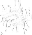
- FIG. 2 schematically shows a section of the intermediate drive 19 in a perspective view Fig. 1
- the intermediate drive 19 has an intermediate drive shaft 20 which is rotatably mounted on two bearing units 21.
- the bearing units 21 each comprise a roller bearing 21c arranged on the intermediate drive shaft 20, in order to enable play-free mounting and thus a particularly precise motion guidance of the plunger 16.
- the bearing units 21 are connected to the press frame 2.
- an intermediate drive gear 22 is arranged, which has a connecting rod 23 with shaft 23 a for connection to a pressure point 26.
- the intermediate drive gear 22 comprises a rolling bearing 25 with an eccentric receiving unit 30 arranged in the rolling bearing 25.
- the eccentric receiving unit 30 is connected to the intermediate drive shaft 20. This extends here through the eccentric guide unit 30 to both bearing units 21.
- a position-controlled motor (not shown here), such as, for example, a servo motor, connected to the intermediate drive shaft 20.
- the connecting rod 23 is rotatably connected via its shaft 23 a to the pressure point 26.
- a two rolling bearings 29 comprehensive pivot bearing 24 is formed.
- the pressure point 26 is coupled to the plunger 16.
- a clamping device 32 is arranged for bracing the intermediate drive 19 against the main drive unit 3.
- the tensioning device 32 is designed as a wedge system for moving the intermediate drive in the vertical direction to the main drive unit.
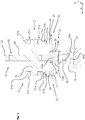
- Fig. 3 schematically shows in a cross section of the cutout of the intermediate drive Fig. 2 ,
- bearing units 21 with intermediate drive shaft 20 the intermediate drive gear 22 with connecting rod 23, shaft 23a, roller bearing 25, eccentric guide unit 30 and connected via the pivot bearing 24 with the shaft 23 pressure point 26 with plunger 16th
- the bearing units 21 are formed similarly to the intermediate drive gear 22 and have a receiving ring 21 a with shank 21 b and a rolling bearing 21 c designed to support the intermediate drive shaft 20.
- the storage units 21 are also spring-mounted in the vertical direction V.
- the free ends of the shafts 21b are formed as a piston 21d, which are mounted in a cylindrical receptacle 27, wherein in each case a hydraulic pad 28 is provided as a spring.
- the hydraulic pad 28 is designed as a cutting impact damping, for example, to absorb and cushion the occurring during the coupling of the drive unit 4 or the penetration of the plunger 16 during cutting movements high forces. While in a hydraulic overload protection the squirting hydraulic fluid must be pumped back in the idle state of the forming device 1, the cutting impact damping 31 is designed such that the exiting hydraulic fluid is automatically and promptly returned after discharge.
- the pivot bearing 24 is formed at the lower end of the shaft 23a in the horizontal direction H outwardly extending rotary shaft portions 23b, on each of which a rolling bearing 29, the pressure point 26 is rotatably mounted.
- the pressure point 26 is in turn resiliently mounted in the plunger 16 in the vertical direction V and has for this purpose at its free end a piston mold 26a, which is mounted hydraulically in a cylinder receptacle 16a in the plunger 16.
- the hydraulic storage is also carried out via a hydraulic pad 31, which is designed as an overload protection.
- the intermediate drive 19 takes over the positioning movement of the plunger 16. That is, the intermediate drive 19 moves the plunger 16 with the upper tool in a precisely predetermined position, for example.
- the drive motor with flywheel is coupled to the drive shaft 4, so that the force of the drive motor with the flywheel via the eccentric guide unit 5 and the toggle mechanism 6 are used for forming the workpiece.
- the drive motor can be coupled out and the intermediate drive 19 lifts the plunger 16 with the upper tool with a positioning movement in an open position.
- the workpiece can be processed otherwise or it is removed from the press.
- this can be removed from the forming device and a new workpiece can be inserted.
- the intermediate drive also makes it possible, for example, to set up the ram on the workpiece and to hold it in the mounted position in order to produce a bond to the workpiece or several workpieces with a low work force, for example. If particularly high manpower is required for the second machining of the workpiece, the main drive can be coupled in for this purpose.
- the plunger 16 can be positioned particularly accurately. Further, since the bearing 21 of the intermediate drive 19 and the connecting rod 26 does not have to withstand high Umformlasten and therefore may have rolling bearings, the plunger 16 is movable approximately free of play, whereby the precision of the movement is significantly improved.
Landscapes
- Engineering & Computer Science (AREA)
- Mechanical Engineering (AREA)
- Press Drives And Press Lines (AREA)
Applications Claiming Priority (1)
| Application Number | Priority Date | Filing Date | Title |
|---|---|---|---|
| DE102016107594.9A DE102016107594A1 (de) | 2016-04-25 | 2016-04-25 | Spielfreier Zwischenantrieb einer Presse mit Servomotor |
Publications (2)
| Publication Number | Publication Date |
|---|---|
| EP3243645A1 true EP3243645A1 (fr) | 2017-11-15 |
| EP3243645B1 EP3243645B1 (fr) | 2020-04-01 |
Family
ID=58644885
Family Applications (1)
| Application Number | Title | Priority Date | Filing Date |
|---|---|---|---|
| EP17168064.8A Active EP3243645B1 (fr) | 2016-04-25 | 2017-04-25 | Dispositif de façonnage et son procédé de commande |
Country Status (2)
| Country | Link |
|---|---|
| EP (1) | EP3243645B1 (fr) |
| DE (1) | DE102016107594A1 (fr) |
Cited By (1)
| Publication number | Priority date | Publication date | Assignee | Title |
|---|---|---|---|---|
| CN110280632A (zh) * | 2019-07-22 | 2019-09-27 | 南京邮电大学 | 基于复合驱动的高速重载机械式全电伺服数控折弯机 |
Citations (8)
| Publication number | Priority date | Publication date | Assignee | Title |
|---|---|---|---|---|
| EP0250610A1 (fr) * | 1986-06-20 | 1988-01-07 | E. Bruderer Maschinenfabrik AG | Presse à genouillère, à découper et à déformer |
| US20010039888A1 (en) * | 2000-05-11 | 2001-11-15 | Shozo Imanishi | Slide drive device for a press |
| DE102005001878B3 (de) | 2005-01-14 | 2006-08-03 | Schuler Pressen Gmbh & Co. Kg | Servopresse mit Kniehebelgetriebe |
| DE102005038583A1 (de) * | 2005-08-16 | 2007-02-22 | Schuler Pressen Gmbh & Co. Kg | Pressen-Antriebsmodul und Verfahren zur Bereitstellung einer Pressenbaureihe |
| DE102006006312A1 (de) * | 2006-02-10 | 2007-08-16 | Pressenservice Scheitza Gmbh | Servo-Presse |
| DE102009032110B3 (de) * | 2009-07-08 | 2010-12-30 | Müller Weingarten AG | Stößelantrieb für mechanische Exzenterpressen |
| US20130247781A1 (en) * | 2012-03-23 | 2013-09-26 | Schuler Pressen Gmbh | Press with two drive motors |
| DE102014111683A1 (de) | 2014-08-15 | 2016-02-18 | Georg Maschinentechnik GmbH & Co. KG | Pressenantrieb für eine Umformvorrichtung |
Family Cites Families (2)
| Publication number | Priority date | Publication date | Assignee | Title |
|---|---|---|---|---|
| KR20130118212A (ko) * | 2010-05-20 | 2013-10-29 | 코스쿠노즈 메탈 폼 마키나 엔듀스트리 브이이 티아이씨. 에이.에스. | 회전 운동을 다른 운동 특징으로 전환하는 메카니즘 |
| DE102011013549B4 (de) * | 2011-03-10 | 2014-01-09 | Schuler Pressen Gmbh | Mechanische Umformmaschine, insbesondere Kurbelpresse |
-
2016
- 2016-04-25 DE DE102016107594.9A patent/DE102016107594A1/de not_active Withdrawn
-
2017
- 2017-04-25 EP EP17168064.8A patent/EP3243645B1/fr active Active
Patent Citations (8)
| Publication number | Priority date | Publication date | Assignee | Title |
|---|---|---|---|---|
| EP0250610A1 (fr) * | 1986-06-20 | 1988-01-07 | E. Bruderer Maschinenfabrik AG | Presse à genouillère, à découper et à déformer |
| US20010039888A1 (en) * | 2000-05-11 | 2001-11-15 | Shozo Imanishi | Slide drive device for a press |
| DE102005001878B3 (de) | 2005-01-14 | 2006-08-03 | Schuler Pressen Gmbh & Co. Kg | Servopresse mit Kniehebelgetriebe |
| DE102005038583A1 (de) * | 2005-08-16 | 2007-02-22 | Schuler Pressen Gmbh & Co. Kg | Pressen-Antriebsmodul und Verfahren zur Bereitstellung einer Pressenbaureihe |
| DE102006006312A1 (de) * | 2006-02-10 | 2007-08-16 | Pressenservice Scheitza Gmbh | Servo-Presse |
| DE102009032110B3 (de) * | 2009-07-08 | 2010-12-30 | Müller Weingarten AG | Stößelantrieb für mechanische Exzenterpressen |
| US20130247781A1 (en) * | 2012-03-23 | 2013-09-26 | Schuler Pressen Gmbh | Press with two drive motors |
| DE102014111683A1 (de) | 2014-08-15 | 2016-02-18 | Georg Maschinentechnik GmbH & Co. KG | Pressenantrieb für eine Umformvorrichtung |
Cited By (2)
| Publication number | Priority date | Publication date | Assignee | Title |
|---|---|---|---|---|
| CN110280632A (zh) * | 2019-07-22 | 2019-09-27 | 南京邮电大学 | 基于复合驱动的高速重载机械式全电伺服数控折弯机 |
| CN110280632B (zh) * | 2019-07-22 | 2024-03-26 | 南京邮电大学 | 基于复合驱动的高速重载机械式全电伺服数控折弯机 |
Also Published As
| Publication number | Publication date |
|---|---|
| DE102016107594A1 (de) | 2017-10-26 |
| EP3243645B1 (fr) | 2020-04-01 |
Similar Documents
| Publication | Publication Date | Title |
|---|---|---|
| EP2008799A1 (fr) | Presse à découper | |
| WO2013056805A1 (fr) | Presse | |
| EP2768662B1 (fr) | Presse | |
| EP0384188A2 (fr) | Dispositif de transfert dans une presse de transfert ou machine-outil analogue travaillant le métal par formage | |
| EP3160726B1 (fr) | Presse à châssis en c, améliorée | |
| DE102009055739B4 (de) | Umformmaschine, insbesondere Servopresse | |
| AT507110A1 (de) | Presse zum umformen von material | |
| EP3243645B1 (fr) | Dispositif de façonnage et son procédé de commande | |
| EP0933181A2 (fr) | Dispositif de fermeture de moules pour la fabrication d'objets en résine thermoplastique | |
| EP2243571A1 (fr) | Système de réglage de la course d'une presse mécanique à cinématique de coulisses | |
| EP3448594B1 (fr) | Presse-transfert pourvue d'un serre-flan en c | |
| WO2005021253A2 (fr) | Presse hydraulique | |
| EP2114587B1 (fr) | Presse de formage présentant une fonction de coussin pneumatique intégrée au plateau coulissant | |
| DE2303451C2 (de) | Vorrichtung zum Schmieden von Kurbelwellen, Flanschwellen u.dgl. mittels einer Schmiedepresse | |
| DE2625881A1 (de) | Stufenpresse | |
| EP1893401B1 (fr) | Dispositif d'estampage et/ou de formage de toles, fils metalliques et similaires | |
| DE914098C (de) | Hydraulische Kniehebelpresse | |
| EP3024646B1 (fr) | Module de force et système de pressage modulaire | |
| DE19611611A1 (de) | Presse | |
| WO2010012014A2 (fr) | Presse de formage de matériau | |
| DD268195A1 (de) | Presse | |
| EP2874793B1 (fr) | Unité de fermeture pour une machine de moulage par injection de matière plastique | |
| EP0783955B1 (fr) | Machine de moulage par injection à deux plateaux avec un plateau mobile et un plateau fixe | |
| DE68924179T2 (de) | Zweispurenumwandlungssystem. | |
| EP4013607A1 (fr) | Presse à balles et procédé de mise en balle de matériau déformable |
Legal Events
| Date | Code | Title | Description |
|---|---|---|---|
| PUAI | Public reference made under article 153(3) epc to a published international application that has entered the european phase |
Free format text: ORIGINAL CODE: 0009012 |
|
| STAA | Information on the status of an ep patent application or granted ep patent |
Free format text: STATUS: THE APPLICATION HAS BEEN PUBLISHED |
|
| AK | Designated contracting states |
Kind code of ref document: A1 Designated state(s): AL AT BE BG CH CY CZ DE DK EE ES FI FR GB GR HR HU IE IS IT LI LT LU LV MC MK MT NL NO PL PT RO RS SE SI SK SM TR |
|
| AX | Request for extension of the european patent |
Extension state: BA ME |
|
| STAA | Information on the status of an ep patent application or granted ep patent |
Free format text: STATUS: REQUEST FOR EXAMINATION WAS MADE |
|
| 17P | Request for examination filed |
Effective date: 20180515 |
|
| RBV | Designated contracting states (corrected) |
Designated state(s): AL AT BE BG CH CY CZ DE DK EE ES FI FR GB GR HR HU IE IS IT LI LT LU LV MC MK MT NL NO PL PT RO RS SE SI SK SM TR |
|
| GRAP | Despatch of communication of intention to grant a patent |
Free format text: ORIGINAL CODE: EPIDOSNIGR1 |
|
| STAA | Information on the status of an ep patent application or granted ep patent |
Free format text: STATUS: GRANT OF PATENT IS INTENDED |
|
| INTG | Intention to grant announced |
Effective date: 20191008 |
|
| GRAS | Grant fee paid |
Free format text: ORIGINAL CODE: EPIDOSNIGR3 |
|
| GRAJ | Information related to disapproval of communication of intention to grant by the applicant or resumption of examination proceedings by the epo deleted |
Free format text: ORIGINAL CODE: EPIDOSDIGR1 |
|
| GRAL | Information related to payment of fee for publishing/printing deleted |
Free format text: ORIGINAL CODE: EPIDOSDIGR3 |
|
| STAA | Information on the status of an ep patent application or granted ep patent |
Free format text: STATUS: REQUEST FOR EXAMINATION WAS MADE |
|
| GRAR | Information related to intention to grant a patent recorded |
Free format text: ORIGINAL CODE: EPIDOSNIGR71 |
|
| STAA | Information on the status of an ep patent application or granted ep patent |
Free format text: STATUS: GRANT OF PATENT IS INTENDED |
|
| GRAA | (expected) grant |
Free format text: ORIGINAL CODE: 0009210 |
|
| STAA | Information on the status of an ep patent application or granted ep patent |
Free format text: STATUS: THE PATENT HAS BEEN GRANTED |
|
| INTC | Intention to grant announced (deleted) | ||
| AK | Designated contracting states |
Kind code of ref document: B1 Designated state(s): AL AT BE BG CH CY CZ DE DK EE ES FI FR GB GR HR HU IE IS IT LI LT LU LV MC MK MT NL NO PL PT RO RS SE SI SK SM TR |
|
| INTG | Intention to grant announced |
Effective date: 20200221 |
|
| REG | Reference to a national code |
Ref country code: GB Ref legal event code: FG4D Free format text: NOT ENGLISH |
|
| REG | Reference to a national code |
Ref country code: CH Ref legal event code: EP Ref country code: AT Ref legal event code: REF Ref document number: 1250840 Country of ref document: AT Kind code of ref document: T Effective date: 20200415 |
|
| REG | Reference to a national code |
Ref country code: DE Ref legal event code: R096 Ref document number: 502017004440 Country of ref document: DE |
|
| REG | Reference to a national code |
Ref country code: IE Ref legal event code: FG4D Free format text: LANGUAGE OF EP DOCUMENT: GERMAN |
|
| REG | Reference to a national code |
Ref country code: CH Ref legal event code: NV Representative=s name: PATENTANWALT DIPL.-ING. (UNI.) WOLFGANG HEISEL, CH |
|
| PG25 | Lapsed in a contracting state [announced via postgrant information from national office to epo] |
Ref country code: BG Free format text: LAPSE BECAUSE OF FAILURE TO SUBMIT A TRANSLATION OF THE DESCRIPTION OR TO PAY THE FEE WITHIN THE PRESCRIBED TIME-LIMIT Effective date: 20200701 |
|
| REG | Reference to a national code |
Ref country code: NL Ref legal event code: MP Effective date: 20200401 |
|
| REG | Reference to a national code |
Ref country code: LT Ref legal event code: MG4D |
|
| PG25 | Lapsed in a contracting state [announced via postgrant information from national office to epo] |
Ref country code: FI Free format text: LAPSE BECAUSE OF FAILURE TO SUBMIT A TRANSLATION OF THE DESCRIPTION OR TO PAY THE FEE WITHIN THE PRESCRIBED TIME-LIMIT Effective date: 20200401 Ref country code: GR Free format text: LAPSE BECAUSE OF FAILURE TO SUBMIT A TRANSLATION OF THE DESCRIPTION OR TO PAY THE FEE WITHIN THE PRESCRIBED TIME-LIMIT Effective date: 20200702 Ref country code: NO Free format text: LAPSE BECAUSE OF FAILURE TO SUBMIT A TRANSLATION OF THE DESCRIPTION OR TO PAY THE FEE WITHIN THE PRESCRIBED TIME-LIMIT Effective date: 20200701 Ref country code: LT Free format text: LAPSE BECAUSE OF FAILURE TO SUBMIT A TRANSLATION OF THE DESCRIPTION OR TO PAY THE FEE WITHIN THE PRESCRIBED TIME-LIMIT Effective date: 20200401 Ref country code: PT Free format text: LAPSE BECAUSE OF FAILURE TO SUBMIT A TRANSLATION OF THE DESCRIPTION OR TO PAY THE FEE WITHIN THE PRESCRIBED TIME-LIMIT Effective date: 20200817 Ref country code: NL Free format text: LAPSE BECAUSE OF FAILURE TO SUBMIT A TRANSLATION OF THE DESCRIPTION OR TO PAY THE FEE WITHIN THE PRESCRIBED TIME-LIMIT Effective date: 20200401 Ref country code: IS Free format text: LAPSE BECAUSE OF FAILURE TO SUBMIT A TRANSLATION OF THE DESCRIPTION OR TO PAY THE FEE WITHIN THE PRESCRIBED TIME-LIMIT Effective date: 20200801 Ref country code: SE Free format text: LAPSE BECAUSE OF FAILURE TO SUBMIT A TRANSLATION OF THE DESCRIPTION OR TO PAY THE FEE WITHIN THE PRESCRIBED TIME-LIMIT Effective date: 20200401 Ref country code: CZ Free format text: LAPSE BECAUSE OF FAILURE TO SUBMIT A TRANSLATION OF THE DESCRIPTION OR TO PAY THE FEE WITHIN THE PRESCRIBED TIME-LIMIT Effective date: 20200401 |
|
| PG25 | Lapsed in a contracting state [announced via postgrant information from national office to epo] |
Ref country code: RS Free format text: LAPSE BECAUSE OF FAILURE TO SUBMIT A TRANSLATION OF THE DESCRIPTION OR TO PAY THE FEE WITHIN THE PRESCRIBED TIME-LIMIT Effective date: 20200401 Ref country code: LV Free format text: LAPSE BECAUSE OF FAILURE TO SUBMIT A TRANSLATION OF THE DESCRIPTION OR TO PAY THE FEE WITHIN THE PRESCRIBED TIME-LIMIT Effective date: 20200401 Ref country code: HR Free format text: LAPSE BECAUSE OF FAILURE TO SUBMIT A TRANSLATION OF THE DESCRIPTION OR TO PAY THE FEE WITHIN THE PRESCRIBED TIME-LIMIT Effective date: 20200401 |
|
| PG25 | Lapsed in a contracting state [announced via postgrant information from national office to epo] |
Ref country code: AL Free format text: LAPSE BECAUSE OF FAILURE TO SUBMIT A TRANSLATION OF THE DESCRIPTION OR TO PAY THE FEE WITHIN THE PRESCRIBED TIME-LIMIT Effective date: 20200401 |
|
| REG | Reference to a national code |
Ref country code: DE Ref legal event code: R097 Ref document number: 502017004440 Country of ref document: DE |
|
| PG25 | Lapsed in a contracting state [announced via postgrant information from national office to epo] |
Ref country code: MC Free format text: LAPSE BECAUSE OF FAILURE TO SUBMIT A TRANSLATION OF THE DESCRIPTION OR TO PAY THE FEE WITHIN THE PRESCRIBED TIME-LIMIT Effective date: 20200401 Ref country code: ES Free format text: LAPSE BECAUSE OF FAILURE TO SUBMIT A TRANSLATION OF THE DESCRIPTION OR TO PAY THE FEE WITHIN THE PRESCRIBED TIME-LIMIT Effective date: 20200401 Ref country code: LU Free format text: LAPSE BECAUSE OF NON-PAYMENT OF DUE FEES Effective date: 20200425 Ref country code: DK Free format text: LAPSE BECAUSE OF FAILURE TO SUBMIT A TRANSLATION OF THE DESCRIPTION OR TO PAY THE FEE WITHIN THE PRESCRIBED TIME-LIMIT Effective date: 20200401 Ref country code: IT Free format text: LAPSE BECAUSE OF FAILURE TO SUBMIT A TRANSLATION OF THE DESCRIPTION OR TO PAY THE FEE WITHIN THE PRESCRIBED TIME-LIMIT Effective date: 20200401 Ref country code: RO Free format text: LAPSE BECAUSE OF FAILURE TO SUBMIT A TRANSLATION OF THE DESCRIPTION OR TO PAY THE FEE WITHIN THE PRESCRIBED TIME-LIMIT Effective date: 20200401 Ref country code: SM Free format text: LAPSE BECAUSE OF FAILURE TO SUBMIT A TRANSLATION OF THE DESCRIPTION OR TO PAY THE FEE WITHIN THE PRESCRIBED TIME-LIMIT Effective date: 20200401 Ref country code: EE Free format text: LAPSE BECAUSE OF FAILURE TO SUBMIT A TRANSLATION OF THE DESCRIPTION OR TO PAY THE FEE WITHIN THE PRESCRIBED TIME-LIMIT Effective date: 20200401 |
|
| REG | Reference to a national code |
Ref country code: BE Ref legal event code: MM Effective date: 20200430 |
|
| PLBE | No opposition filed within time limit |
Free format text: ORIGINAL CODE: 0009261 |
|
| STAA | Information on the status of an ep patent application or granted ep patent |
Free format text: STATUS: NO OPPOSITION FILED WITHIN TIME LIMIT |
|
| PG25 | Lapsed in a contracting state [announced via postgrant information from national office to epo] |
Ref country code: BE Free format text: LAPSE BECAUSE OF NON-PAYMENT OF DUE FEES Effective date: 20200430 Ref country code: PL Free format text: LAPSE BECAUSE OF FAILURE TO SUBMIT A TRANSLATION OF THE DESCRIPTION OR TO PAY THE FEE WITHIN THE PRESCRIBED TIME-LIMIT Effective date: 20200401 Ref country code: SK Free format text: LAPSE BECAUSE OF FAILURE TO SUBMIT A TRANSLATION OF THE DESCRIPTION OR TO PAY THE FEE WITHIN THE PRESCRIBED TIME-LIMIT Effective date: 20200401 |
|
| 26N | No opposition filed |
Effective date: 20210112 |
|
| PG25 | Lapsed in a contracting state [announced via postgrant information from national office to epo] |
Ref country code: IE Free format text: LAPSE BECAUSE OF NON-PAYMENT OF DUE FEES Effective date: 20200425 Ref country code: FR Free format text: LAPSE BECAUSE OF NON-PAYMENT OF DUE FEES Effective date: 20200601 |
|
| PG25 | Lapsed in a contracting state [announced via postgrant information from national office to epo] |
Ref country code: SI Free format text: LAPSE BECAUSE OF FAILURE TO SUBMIT A TRANSLATION OF THE DESCRIPTION OR TO PAY THE FEE WITHIN THE PRESCRIBED TIME-LIMIT Effective date: 20200401 |
|
| PGFP | Annual fee paid to national office [announced via postgrant information from national office to epo] |
Ref country code: DE Payment date: 20210427 Year of fee payment: 5 |
|
| GBPC | Gb: european patent ceased through non-payment of renewal fee |
Effective date: 20210425 |
|
| PG25 | Lapsed in a contracting state [announced via postgrant information from national office to epo] |
Ref country code: GB Free format text: LAPSE BECAUSE OF NON-PAYMENT OF DUE FEES Effective date: 20210425 |
|
| PG25 | Lapsed in a contracting state [announced via postgrant information from national office to epo] |
Ref country code: TR Free format text: LAPSE BECAUSE OF FAILURE TO SUBMIT A TRANSLATION OF THE DESCRIPTION OR TO PAY THE FEE WITHIN THE PRESCRIBED TIME-LIMIT Effective date: 20200401 Ref country code: MT Free format text: LAPSE BECAUSE OF FAILURE TO SUBMIT A TRANSLATION OF THE DESCRIPTION OR TO PAY THE FEE WITHIN THE PRESCRIBED TIME-LIMIT Effective date: 20200401 Ref country code: CY Free format text: LAPSE BECAUSE OF FAILURE TO SUBMIT A TRANSLATION OF THE DESCRIPTION OR TO PAY THE FEE WITHIN THE PRESCRIBED TIME-LIMIT Effective date: 20200401 |
|
| PG25 | Lapsed in a contracting state [announced via postgrant information from national office to epo] |
Ref country code: MK Free format text: LAPSE BECAUSE OF FAILURE TO SUBMIT A TRANSLATION OF THE DESCRIPTION OR TO PAY THE FEE WITHIN THE PRESCRIBED TIME-LIMIT Effective date: 20200401 |
|
| PGFP | Annual fee paid to national office [announced via postgrant information from national office to epo] |
Ref country code: CH Payment date: 20220421 Year of fee payment: 6 Ref country code: AT Payment date: 20220414 Year of fee payment: 6 |
|
| REG | Reference to a national code |
Ref country code: DE Ref legal event code: R119 Ref document number: 502017004440 Country of ref document: DE |
|
| PG25 | Lapsed in a contracting state [announced via postgrant information from national office to epo] |
Ref country code: DE Free format text: LAPSE BECAUSE OF NON-PAYMENT OF DUE FEES Effective date: 20221103 |
|
| REG | Reference to a national code |
Ref country code: CH Ref legal event code: PL |
|
| REG | Reference to a national code |
Ref country code: AT Ref legal event code: MM01 Ref document number: 1250840 Country of ref document: AT Kind code of ref document: T Effective date: 20230425 |
|
| PG25 | Lapsed in a contracting state [announced via postgrant information from national office to epo] |
Ref country code: LI Free format text: LAPSE BECAUSE OF NON-PAYMENT OF DUE FEES Effective date: 20230430 Ref country code: CH Free format text: LAPSE BECAUSE OF NON-PAYMENT OF DUE FEES Effective date: 20230430 Ref country code: AT Free format text: LAPSE BECAUSE OF NON-PAYMENT OF DUE FEES Effective date: 20230425 |