EP3243988A1 - Porte basculante facile à installer - Google Patents
Porte basculante facile à installer Download PDFInfo
- Publication number
- EP3243988A1 EP3243988A1 EP17169881.4A EP17169881A EP3243988A1 EP 3243988 A1 EP3243988 A1 EP 3243988A1 EP 17169881 A EP17169881 A EP 17169881A EP 3243988 A1 EP3243988 A1 EP 3243988A1
- Authority
- EP
- European Patent Office
- Prior art keywords
- spring packet
- door
- profiles
- door panels
- spring
- Prior art date
- Legal status (The legal status is an assumption and is not a legal conclusion. Google has not performed a legal analysis and makes no representation as to the accuracy of the status listed.)
- Granted
Links
Images

Classifications
-
- E—FIXED CONSTRUCTIONS
- E06—DOORS, WINDOWS, SHUTTERS, OR ROLLER BLINDS IN GENERAL; LADDERS
- E06B—FIXED OR MOVABLE CLOSURES FOR OPENINGS IN BUILDINGS, VEHICLES, FENCES OR LIKE ENCLOSURES IN GENERAL, e.g. DOORS, WINDOWS, BLINDS, GATES
- E06B3/00—Window sashes, door leaves, or like elements for closing wall or like openings; Layout of fixed or moving closures, e.g. windows in wall or like openings; Features of rigidly-mounted outer frames relating to the mounting of wing frames
- E06B3/32—Arrangements of wings characterised by the manner of movement; Arrangements of movable wings in openings; Features of wings or frames relating solely to the manner of movement of the wing
- E06B3/48—Wings connected at their edges, e.g. foldable wings
- E06B3/485—Sectional doors
- E06B3/486—Sectional doors with hinges being at least partially integral part of the section panels
-
- E—FIXED CONSTRUCTIONS
- E05—LOCKS; KEYS; WINDOW OR DOOR FITTINGS; SAFES
- E05D—HINGES OR SUSPENSION DEVICES FOR DOORS, WINDOWS OR WINGS
- E05D13/00—Accessories for sliding or lifting wings, e.g. pulleys, safety catches
- E05D13/10—Counterbalance devices
- E05D13/12—Counterbalance devices with springs
- E05D13/1207—Counterbalance devices with springs with tension springs
- E05D13/1215—Counterbalance devices with springs with tension springs specially adapted for overhead wings
Definitions
- the present invention relates to a method of installing an overhead door by securing profiles at least provided with a spring packet around a doorway, movable door panels which are pivotally attached to each other being arranged between said profiles, after which the spring packet is coupled to the door panels and the overhead door is adjusted.
- the present invention also relates to a profile which is provided with a spring packet and which can suitably be used in the method.
- a drawback of the known method is that the interconnected door panels mounted between the profiles represent a considerable weight which has to be lifted by sometimes at least 3 or 4 persons in order to meet the safety regulations concerning the maximum acceptable lifting weight.
- the method according to the invention is characterized in that the overhead door is installed by securing profiles at least provided with a spring packet around a doorway, movable door panels which are pivotally attached to each other being arranged between said profiles, after which the spring packet already subjected to a tensile stress is coupled to the door panels which are subsequently moved upwards by means of the relaxing spring packet, after which the overhead door is adjusted.
- An advantage of the method according to the invention resides in that the tensile stress in the already pre-compressed spring packet is beneficially used as a released lifting force when the interconnected door panels are moved upwards by inter alia the springs.
- less lifting force and fewer staff during installation is required, while the relevant ergonomic regulations are still met.
- the risk of calamities such as the door panels getting stuck, warping or falling to the ground is reduced when the door panels are lifted using less manpower.
- the method according to the invention can be carried out with greater safety because the spring force exerted by the springs during lifting the interconnected door panels enables better control of the lifting operation.
- An embodiment of the method according to the invention is characterized in that the door panels rest on a rope frame engaging, with the spring packet, on either side of a removable locking element, and in that the spring packet subjected to a tensile stress and the interconnected door panels are coupled by removing said locking element.
- Removing said locking element is easier if the abovementioned coupling operation is carried out when the forces exerted by the spring packet and the interconnected door panels at the location of the locking element are more equal to each other.
- a further embodiment of the method according to the invention is characterized in that profiles are located on either side of the door, which profiles each comprise a pre-compressed spring packet.
- both sides of the interconnected door panels to be lifted are supported by the spring packet during installation of the door.
- the risk of warping of the panels when lifting them is negligibly small.
- a further embodiment of the method according to the invention is characterized in that the interconnected door panels are subsequently moved downwards against the spring force of the spring packet and, if necessary, a next door panel is secured thereon.
- the door panels can be readily moved downwards against the spring force of the spring packet and maintained in that position, therefore a next, possibly last door section- if it has not been fitted yet- can be readily provided.
- the invention further relates to a profile which can suitably be used in the method described herein, and which is characterized in that the spring packet in the relevant profile comprises a plurality of pre-compressed extension springs.
- the pre-compressed spring packet is safely confined in the profile.
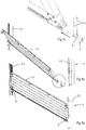
- FIGs 1a and 1b show how in the first instance a door panel 1-1 forming part of an overhead door 2, which is also referred to as sectional door, is fitted between vertical profiles 3-1, 3-2.
- the overhead door 2 which can be raised, is fitted in and/or to a doorway.
- the profiles 3-1, 3-2 are attached to the doorway and part of the profiles 3-1, 3-2 comprise a track for wheels 4 shown in figure 1c , thereby allowing the door panels 1 to be coupled with said wheels to move within said track.
- the lower edge of the lowest door panel 1-1 is temporarily restrained in a position slightly above the bottom of the doorway.
- a stop 5 can be inserted into the respective vertical profile 3-1, 3-2, which precludes a downward movement of the panel 1-1.
- a space is thus created allowing one or more panels to be interconnected to be moved upwards at a later stage.
- the panel 1-1 is attached at the angular points, not necessarily all four angular points however, to the relevant wheels 4.
- the axle 6 of only the lowest wheels 4 is connected to a rope frame, which will be explained in more detail hereinafter, which includes the rope 7 which is rotatable about the axle 6, and which is duplicated in this case.
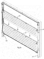
- FIG 2a schematically shows how the second door panel 1-2 comprising wheels 4 is movably fitted, in a similar manner, between the profiles 3-1 and 3-2 and has a hinged connection to the first door profile 1-1. In general, these wheels 4 are not connected to the rope frame.
- Figure 2b shows how the third door panel 1-3 is mounted in the same manner as the second door panel 1-2.
- This figure also shows an example of the known upper structure comprising horizontal profiles 3-3, 3-4 which are also provided with a track in which the rollers or wheels 4 can travel.
- a bent profile 3-5 having a curved track is situated between the vertical and the horizontal profiles.
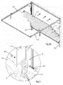
- Figure 3 shows a spring packet 8, in this case at the level of the third, fitted, door panel 1-3, which spring packet is attached at the lower side to a respective vertical profile 3-1, 3-2 and at the upper side, while being pre-compressed, to a locking element 9 which is also attached to the respective profile 3-1, 3-2.
- the spring packet 8 is extended.
- the relevant profiles 3-1, 3-2 accommodating the spring packet 8 will be pre-compressed at the factory, so that precompressing the spring packet 8 at the place of installation and assembly of the door 2, with all the associated disadvantages, is not necessary.
- the spring packet can be pre-compressed on site prior to the installation of the overhead door 2, while keeping a few briefly indicated advantages of the method explained herein.
- the locking element 9 in this case a wing bolt 9-1 which can be readily manually released, and behind which there is a nut 9-2 which is a tight fit in an opening of the profile 3-1, 3-2, is surrounded by duplicate ropes 7 extending upwards in the profile 3-1, 3-2. These ropes are routed downwards to the abovementioned axle 6 via pulleys, not shown, in the said profiles.
- the idea is that at the location of the locking element 9, the weight of the fitted door panels 1-1, 1-2, 1-3 in combination with, if necessary, for example the force exerted by the foot of the installer, a balance is reached with respect to the force exerted by the spring packet 8 such that the locked state 9 can be readily cancelled, or that the wing bolt 9-1 can be safely removed.
- Figure 4 shows the situation obtained after, in this case three, interconnected door panels 1-1, 1-2, 1-3 have been raised and maintained in the raised position, in this case temporarily by means of a gluing clamp 10, after which the necessary settings and adjustments for, inter alia, low-torsion and low-noise running of the wheels 4 in the track when opening and closing the door 1, and of the rope frame and/or of the then unstressed spring packet 8 can take place.
- Figure 5 shows the final situation in which, subsequently, the in this case fourth and final so-termed upper door panel 1-4 is fitted.
- the ropes and the extension springs in the spring packet 8 have been implemented in duplicate.
- the springs are implemented as double extension springs and arranged in parallel.
- the spring packet 8 comprises coaxial and hence nested, i.e., one embedded inside the other, extension springs.
- the door 2 can comprise a desired number of door panels 1, in which a well-known wicket door may or may not be fitted.
Landscapes
- Engineering & Computer Science (AREA)
- Civil Engineering (AREA)
- Structural Engineering (AREA)
- Closing And Opening Devices For Wings, And Checks For Wings (AREA)
- Wing Frames And Configurations (AREA)
Applications Claiming Priority (1)
| Application Number | Priority Date | Filing Date | Title |
|---|---|---|---|
| NL2016738A NL2016738B1 (nl) | 2016-05-09 | 2016-05-09 | Eenvoudig te installeren overheaddeur. |
Publications (3)
| Publication Number | Publication Date |
|---|---|
| EP3243988A1 true EP3243988A1 (fr) | 2017-11-15 |
| EP3243988C0 EP3243988C0 (fr) | 2023-06-21 |
| EP3243988B1 EP3243988B1 (fr) | 2023-06-21 |
Family
ID=56292846
Family Applications (1)
| Application Number | Title | Priority Date | Filing Date |
|---|---|---|---|
| EP17169881.4A Active EP3243988B1 (fr) | 2016-05-09 | 2017-05-08 | Porte basculante facile à installer |
Country Status (2)
| Country | Link |
|---|---|
| EP (1) | EP3243988B1 (fr) |
| NL (1) | NL2016738B1 (fr) |
Cited By (4)
| Publication number | Priority date | Publication date | Assignee | Title |
|---|---|---|---|---|
| CN111827822A (zh) * | 2020-07-31 | 2020-10-27 | 杭州床邢科技有限公司 | 一种基于滑动式铝合金门窗的滑轮结构 |
| EP3943699A1 (fr) * | 2020-07-23 | 2022-01-26 | Doco International B.V. NL | Procédé d'installation d'un portail de garage et portail de garage |
| US12091896B2 (en) | 2020-01-22 | 2024-09-17 | Assa Abloy Entrance Systems Ab | Method of arranging an overhead sectional door |
| EP4686798A1 (fr) | 2024-07-29 | 2026-02-04 | Condoor Group B.V. | Porte basculante préinstallée et procédé de conversion de la porte préinstallée en une porte basculante qui est prête à l'utilisation |
Citations (4)
| Publication number | Priority date | Publication date | Assignee | Title |
|---|---|---|---|---|
| US2045101A (en) * | 1932-09-03 | 1936-06-23 | Stanley Works | Articulated overhead door |
| DE3200945C1 (de) * | 1982-01-14 | 1983-05-19 | Döring, Erich, 9442 Berneck, St. Gallen | Garagenschwingtor mit einer Fangvorrichtung für den Torflügel |
| DE19713458A1 (de) * | 1996-03-29 | 1997-11-20 | Hoermann Kg | Tor mit einer Zugseileinrichtung |
| DE29815487U1 (de) * | 1998-08-28 | 2000-01-13 | Hörmann KG Amshausen, 33803 Steinhagen | Einblatt-Überkopftor mit einer über ein Hebelwerk wirkenden Gewichtsausgleicheinrichtung |
Family Cites Families (2)
| Publication number | Priority date | Publication date | Assignee | Title |
|---|---|---|---|---|
| US5615723A (en) * | 1994-06-16 | 1997-04-01 | Clopay Building Products Company, Inc. | Extension spring system for an overhead door |
| CA2228446C (fr) * | 1998-01-30 | 2001-08-07 | Arthur A. Mihalcheon | Ensemble de type ressort de traction pour lever une porte en sections |
-
2016
- 2016-05-09 NL NL2016738A patent/NL2016738B1/nl active
-
2017
- 2017-05-08 EP EP17169881.4A patent/EP3243988B1/fr active Active
Patent Citations (4)
| Publication number | Priority date | Publication date | Assignee | Title |
|---|---|---|---|---|
| US2045101A (en) * | 1932-09-03 | 1936-06-23 | Stanley Works | Articulated overhead door |
| DE3200945C1 (de) * | 1982-01-14 | 1983-05-19 | Döring, Erich, 9442 Berneck, St. Gallen | Garagenschwingtor mit einer Fangvorrichtung für den Torflügel |
| DE19713458A1 (de) * | 1996-03-29 | 1997-11-20 | Hoermann Kg | Tor mit einer Zugseileinrichtung |
| DE29815487U1 (de) * | 1998-08-28 | 2000-01-13 | Hörmann KG Amshausen, 33803 Steinhagen | Einblatt-Überkopftor mit einer über ein Hebelwerk wirkenden Gewichtsausgleicheinrichtung |
Cited By (5)
| Publication number | Priority date | Publication date | Assignee | Title |
|---|---|---|---|---|
| US12091896B2 (en) | 2020-01-22 | 2024-09-17 | Assa Abloy Entrance Systems Ab | Method of arranging an overhead sectional door |
| EP3943699A1 (fr) * | 2020-07-23 | 2022-01-26 | Doco International B.V. NL | Procédé d'installation d'un portail de garage et portail de garage |
| CN111827822A (zh) * | 2020-07-31 | 2020-10-27 | 杭州床邢科技有限公司 | 一种基于滑动式铝合金门窗的滑轮结构 |
| EP4686798A1 (fr) | 2024-07-29 | 2026-02-04 | Condoor Group B.V. | Porte basculante préinstallée et procédé de conversion de la porte préinstallée en une porte basculante qui est prête à l'utilisation |
| NL2038354B1 (en) | 2024-07-29 | 2026-02-17 | Condoor Group B V | A preinstalled overhead door and a method for converting the preinstalled door into an overhead door that is ready to use |
Also Published As
| Publication number | Publication date |
|---|---|
| EP3243988C0 (fr) | 2023-06-21 |
| NL2016738B1 (nl) | 2017-11-16 |
| EP3243988B1 (fr) | 2023-06-21 |
Similar Documents
| Publication | Publication Date | Title |
|---|---|---|
| EP3243988B1 (fr) | Porte basculante facile à installer | |
| AU2007321143B2 (en) | Method and apparatus for installing an elevator without machine room during construction of a building, and use of a hoisting machine | |
| EP2114810B1 (fr) | Entraînement pour une cabine d'ascenseur, à maintenance pouvant être effectuée à partir de ladite cabine | |
| CN109476456B (zh) | 电梯装置和电梯 | |
| CN101415900A (zh) | 带安全屏障的垂直活动门 | |
| US20190135586A1 (en) | Elevator arrangement with low headroom | |
| US9243435B1 (en) | Safety fall arrestor and wind lock for vertical lift doors | |
| KR101346387B1 (ko) | 갱폼의 작업발판용 안전도어 | |
| US8701827B2 (en) | Climbing screen support system | |
| KR101766914B1 (ko) | 엘리베이터용 수직 개폐식 도어의 상부 구동축 구동시스템 | |
| US2750004A (en) | Combined load-equalizing and safety device for lifts | |
| EP2774887B1 (fr) | Unité de seuil de porte et procédé pour une unité de porte de palier d'ascenseur | |
| US20110240828A1 (en) | Elevator system and installation method | |
| GB2476704A (en) | An elevator safety system | |
| JP6837567B2 (ja) | エレベータ用ピット梯子装置、及びエレベータ用乗場ドア装置 | |
| CN210976461U (zh) | 一种电梯井内集成式整体施工平台 | |
| US7185382B2 (en) | Airport baggage lift system | |
| EP4406900A1 (fr) | Procédé de montage sans échafaudage d'une installation d'ascenseur dans une cage d'ascenseur | |
| WO2020127567A1 (fr) | Dispositif anti-chute pour élévateur motorisé à entraînement pignon-crémaillère | |
| CN101544330A (zh) | 电梯绳索止振装置 | |
| WO2016125229A1 (fr) | Plaque de carénage d'ascenseur et procédé d'assemblage de plaque de carénage | |
| CA2944817C (fr) | Appareil de longeron destine a un mecanisme d'appareil de forage a contrepoids | |
| KR101764740B1 (ko) | 엘리베이터 승강장문 조립체의 상부 이탈방지구조 | |
| KR102630862B1 (ko) | 엘리베이터 점검용 사다리 | |
| CN220889362U (zh) | 一种高度可调的支撑平台 |
Legal Events
| Date | Code | Title | Description |
|---|---|---|---|
| PUAI | Public reference made under article 153(3) epc to a published international application that has entered the european phase |
Free format text: ORIGINAL CODE: 0009012 |
|
| STAA | Information on the status of an ep patent application or granted ep patent |
Free format text: STATUS: REQUEST FOR EXAMINATION WAS MADE |
|
| 17P | Request for examination filed |
Effective date: 20170508 |
|
| AK | Designated contracting states |
Kind code of ref document: A1 Designated state(s): AL AT BE BG CH CY CZ DE DK EE ES FI FR GB GR HR HU IE IS IT LI LT LU LV MC MK MT NL NO PL PT RO RS SE SI SK SM TR |
|
| AX | Request for extension of the european patent |
Extension state: BA ME |
|
| TPAC | Observations filed by third parties |
Free format text: ORIGINAL CODE: EPIDOSNTIPA |
|
| STAA | Information on the status of an ep patent application or granted ep patent |
Free format text: STATUS: EXAMINATION IS IN PROGRESS |
|
| 17Q | First examination report despatched |
Effective date: 20200722 |
|
| TPAA | Information related to observations by third parties modified |
Free format text: ORIGINAL CODE: EPIDOSCTIPA |
|
| TPAC | Observations filed by third parties |
Free format text: ORIGINAL CODE: EPIDOSNTIPA |
|
| GRAP | Despatch of communication of intention to grant a patent |
Free format text: ORIGINAL CODE: EPIDOSNIGR1 |
|
| STAA | Information on the status of an ep patent application or granted ep patent |
Free format text: STATUS: GRANT OF PATENT IS INTENDED |
|
| INTG | Intention to grant announced |
Effective date: 20221021 |
|
| GRAS | Grant fee paid |
Free format text: ORIGINAL CODE: EPIDOSNIGR3 |
|
| GRAA | (expected) grant |
Free format text: ORIGINAL CODE: 0009210 |
|
| STAA | Information on the status of an ep patent application or granted ep patent |
Free format text: STATUS: THE PATENT HAS BEEN GRANTED |
|
| AK | Designated contracting states |
Kind code of ref document: B1 Designated state(s): AL AT BE BG CH CY CZ DE DK EE ES FI FR GB GR HR HU IE IS IT LI LT LU LV MC MK MT NL NO PL PT RO RS SE SI SK SM TR |
|
| REG | Reference to a national code |
Ref country code: CH Ref legal event code: EP |
|
| REG | Reference to a national code |
Ref country code: DE Ref legal event code: R096 Ref document number: 602017070378 Country of ref document: DE |
|
| REG | Reference to a national code |
Ref country code: AT Ref legal event code: REF Ref document number: 1581012 Country of ref document: AT Kind code of ref document: T Effective date: 20230715 |
|
| REG | Reference to a national code |
Ref country code: IE Ref legal event code: FG4D |
|
| U01 | Request for unitary effect filed |
Effective date: 20230621 |
|
| U07 | Unitary effect registered |
Designated state(s): AT BE BG DE DK EE FI FR IT LT LU LV MT NL PT SE SI Effective date: 20230623 |
|
| U1N | Appointed representative for the unitary patent procedure changed after the registration of the unitary effect |
Representative=s name: VAN BREDA, JACOBUS; NL |
|
| U08 | Date and/or purport of decision on request for unitary effect for the european patent changed [decision is positive] |
Designated state(s): AT BE BG DE DK EE FI FR IT LT LU LV MT NL PT SE SI Effective date: 20230710 |
|
| U08 | Date and/or purport of decision on request for unitary effect for the european patent changed [decision is positive] |
Designated state(s): AT BE BG DE DK EE FI FR IT LT LU LV MT NL PT SE SI Effective date: 20230623 |
|
| REG | Reference to a national code |
Ref country code: LT Ref legal event code: MG9D |
|
| PG25 | Lapsed in a contracting state [announced via postgrant information from national office to epo] |
Ref country code: NO Free format text: LAPSE BECAUSE OF FAILURE TO SUBMIT A TRANSLATION OF THE DESCRIPTION OR TO PAY THE FEE WITHIN THE PRESCRIBED TIME-LIMIT Effective date: 20230921 |
|
| PG25 | Lapsed in a contracting state [announced via postgrant information from national office to epo] |
Ref country code: RS Free format text: LAPSE BECAUSE OF FAILURE TO SUBMIT A TRANSLATION OF THE DESCRIPTION OR TO PAY THE FEE WITHIN THE PRESCRIBED TIME-LIMIT Effective date: 20230621 Ref country code: HR Free format text: LAPSE BECAUSE OF FAILURE TO SUBMIT A TRANSLATION OF THE DESCRIPTION OR TO PAY THE FEE WITHIN THE PRESCRIBED TIME-LIMIT Effective date: 20230621 Ref country code: GR Free format text: LAPSE BECAUSE OF FAILURE TO SUBMIT A TRANSLATION OF THE DESCRIPTION OR TO PAY THE FEE WITHIN THE PRESCRIBED TIME-LIMIT Effective date: 20230922 |
|
| PG25 | Lapsed in a contracting state [announced via postgrant information from national office to epo] |
Ref country code: SK Free format text: LAPSE BECAUSE OF FAILURE TO SUBMIT A TRANSLATION OF THE DESCRIPTION OR TO PAY THE FEE WITHIN THE PRESCRIBED TIME-LIMIT Effective date: 20230621 |
|
| PG25 | Lapsed in a contracting state [announced via postgrant information from national office to epo] |
Ref country code: ES Free format text: LAPSE BECAUSE OF FAILURE TO SUBMIT A TRANSLATION OF THE DESCRIPTION OR TO PAY THE FEE WITHIN THE PRESCRIBED TIME-LIMIT Effective date: 20230621 |
|
| PG25 | Lapsed in a contracting state [announced via postgrant information from national office to epo] |
Ref country code: IS Free format text: LAPSE BECAUSE OF FAILURE TO SUBMIT A TRANSLATION OF THE DESCRIPTION OR TO PAY THE FEE WITHIN THE PRESCRIBED TIME-LIMIT Effective date: 20231021 |
|
| PG25 | Lapsed in a contracting state [announced via postgrant information from national office to epo] |
Ref country code: SM Free format text: LAPSE BECAUSE OF FAILURE TO SUBMIT A TRANSLATION OF THE DESCRIPTION OR TO PAY THE FEE WITHIN THE PRESCRIBED TIME-LIMIT Effective date: 20230621 Ref country code: SK Free format text: LAPSE BECAUSE OF FAILURE TO SUBMIT A TRANSLATION OF THE DESCRIPTION OR TO PAY THE FEE WITHIN THE PRESCRIBED TIME-LIMIT Effective date: 20230621 Ref country code: RO Free format text: LAPSE BECAUSE OF FAILURE TO SUBMIT A TRANSLATION OF THE DESCRIPTION OR TO PAY THE FEE WITHIN THE PRESCRIBED TIME-LIMIT Effective date: 20230621 Ref country code: IS Free format text: LAPSE BECAUSE OF FAILURE TO SUBMIT A TRANSLATION OF THE DESCRIPTION OR TO PAY THE FEE WITHIN THE PRESCRIBED TIME-LIMIT Effective date: 20231021 Ref country code: ES Free format text: LAPSE BECAUSE OF FAILURE TO SUBMIT A TRANSLATION OF THE DESCRIPTION OR TO PAY THE FEE WITHIN THE PRESCRIBED TIME-LIMIT Effective date: 20230621 Ref country code: CZ Free format text: LAPSE BECAUSE OF FAILURE TO SUBMIT A TRANSLATION OF THE DESCRIPTION OR TO PAY THE FEE WITHIN THE PRESCRIBED TIME-LIMIT Effective date: 20230621 |
|
| PG25 | Lapsed in a contracting state [announced via postgrant information from national office to epo] |
Ref country code: PL Free format text: LAPSE BECAUSE OF FAILURE TO SUBMIT A TRANSLATION OF THE DESCRIPTION OR TO PAY THE FEE WITHIN THE PRESCRIBED TIME-LIMIT Effective date: 20230621 |
|
| REG | Reference to a national code |
Ref country code: DE Ref legal event code: R097 Ref document number: 602017070378 Country of ref document: DE |
|
| PLBE | No opposition filed within time limit |
Free format text: ORIGINAL CODE: 0009261 |
|
| STAA | Information on the status of an ep patent application or granted ep patent |
Free format text: STATUS: NO OPPOSITION FILED WITHIN TIME LIMIT |
|
| 26N | No opposition filed |
Effective date: 20240322 |
|
| U20 | Renewal fee for the european patent with unitary effect paid |
Year of fee payment: 8 Effective date: 20240528 |
|
| REG | Reference to a national code |
Ref country code: CH Ref legal event code: PL |
|
| PG25 | Lapsed in a contracting state [announced via postgrant information from national office to epo] |
Ref country code: MC Free format text: LAPSE BECAUSE OF FAILURE TO SUBMIT A TRANSLATION OF THE DESCRIPTION OR TO PAY THE FEE WITHIN THE PRESCRIBED TIME-LIMIT Effective date: 20230621 |
|
| PG25 | Lapsed in a contracting state [announced via postgrant information from national office to epo] |
Ref country code: MC Free format text: LAPSE BECAUSE OF FAILURE TO SUBMIT A TRANSLATION OF THE DESCRIPTION OR TO PAY THE FEE WITHIN THE PRESCRIBED TIME-LIMIT Effective date: 20230621 Ref country code: CH Free format text: LAPSE BECAUSE OF NON-PAYMENT OF DUE FEES Effective date: 20240531 |
|
| PG25 | Lapsed in a contracting state [announced via postgrant information from national office to epo] |
Ref country code: IE Free format text: LAPSE BECAUSE OF NON-PAYMENT OF DUE FEES Effective date: 20240508 |
|
| U20 | Renewal fee for the european patent with unitary effect paid |
Year of fee payment: 9 Effective date: 20250527 |
|
| PG25 | Lapsed in a contracting state [announced via postgrant information from national office to epo] |
Ref country code: CY Free format text: LAPSE BECAUSE OF FAILURE TO SUBMIT A TRANSLATION OF THE DESCRIPTION OR TO PAY THE FEE WITHIN THE PRESCRIBED TIME-LIMIT; INVALID AB INITIO Effective date: 20170508 |
|
| PG25 | Lapsed in a contracting state [announced via postgrant information from national office to epo] |
Ref country code: HU Free format text: LAPSE BECAUSE OF FAILURE TO SUBMIT A TRANSLATION OF THE DESCRIPTION OR TO PAY THE FEE WITHIN THE PRESCRIBED TIME-LIMIT; INVALID AB INITIO Effective date: 20170508 |
|
| PG25 | Lapsed in a contracting state [announced via postgrant information from national office to epo] |
Ref country code: TR Free format text: LAPSE BECAUSE OF FAILURE TO SUBMIT A TRANSLATION OF THE DESCRIPTION OR TO PAY THE FEE WITHIN THE PRESCRIBED TIME-LIMIT Effective date: 20230621 |
|
| U20 | Renewal fee for the european patent with unitary effect paid |
Year of fee payment: 10 Effective date: 20260527 |
|
| PGFP | Annual fee paid to national office [announced via postgrant information from national office to epo] |
Ref country code: GB Payment date: 20260527 Year of fee payment: 10 |