EP3244020B1 - Gasturbinenmotor mit einer leitschaufelanordnung - Google Patents
Gasturbinenmotor mit einer leitschaufelanordnung Download PDFInfo
- Publication number
- EP3244020B1 EP3244020B1 EP17159421.1A EP17159421A EP3244020B1 EP 3244020 B1 EP3244020 B1 EP 3244020B1 EP 17159421 A EP17159421 A EP 17159421A EP 3244020 B1 EP3244020 B1 EP 3244020B1
- Authority
- EP
- European Patent Office
- Prior art keywords
- support surface
- face
- opening
- extending
- towards
- Prior art date
- Legal status (The legal status is an assumption and is not a legal conclusion. Google has not performed a legal analysis and makes no representation as to the accuracy of the status listed.)
- Active
Links
Images

Classifications
-
- F—MECHANICAL ENGINEERING; LIGHTING; HEATING; WEAPONS; BLASTING
- F01—MACHINES OR ENGINES IN GENERAL; ENGINE PLANTS IN GENERAL; STEAM ENGINES
- F01D—NON-POSITIVE DISPLACEMENT MACHINES OR ENGINES, e.g. STEAM TURBINES
- F01D5/00—Blades; Blade-carrying members; Heating, heat-insulating, cooling or antivibration means on the blades or the members
- F01D5/30—Fixing blades to rotors; Blade roots ; Blade spacers
- F01D5/3007—Fixing blades to rotors; Blade roots ; Blade spacers of axial insertion type
-
- F—MECHANICAL ENGINEERING; LIGHTING; HEATING; WEAPONS; BLASTING
- F01—MACHINES OR ENGINES IN GENERAL; ENGINE PLANTS IN GENERAL; STEAM ENGINES
- F01D—NON-POSITIVE DISPLACEMENT MACHINES OR ENGINES, e.g. STEAM TURBINES
- F01D11/00—Preventing or minimising internal leakage of working-fluid, e.g. between stages
- F01D11/005—Sealing means between non relatively rotating elements
-
- F—MECHANICAL ENGINEERING; LIGHTING; HEATING; WEAPONS; BLASTING
- F01—MACHINES OR ENGINES IN GENERAL; ENGINE PLANTS IN GENERAL; STEAM ENGINES
- F01D—NON-POSITIVE DISPLACEMENT MACHINES OR ENGINES, e.g. STEAM TURBINES
- F01D25/00—Component parts, details, or accessories, not provided for in, or of interest apart from, other groups
- F01D25/24—Casings; Casing parts, e.g. diaphragms, casing fastenings
- F01D25/243—Flange connections; Bolting arrangements
-
- F—MECHANICAL ENGINEERING; LIGHTING; HEATING; WEAPONS; BLASTING
- F01—MACHINES OR ENGINES IN GENERAL; ENGINE PLANTS IN GENERAL; STEAM ENGINES
- F01D—NON-POSITIVE DISPLACEMENT MACHINES OR ENGINES, e.g. STEAM TURBINES
- F01D25/00—Component parts, details, or accessories, not provided for in, or of interest apart from, other groups
- F01D25/24—Casings; Casing parts, e.g. diaphragms, casing fastenings
- F01D25/246—Fastening of diaphragms or stator-rings
-
- F—MECHANICAL ENGINEERING; LIGHTING; HEATING; WEAPONS; BLASTING
- F01—MACHINES OR ENGINES IN GENERAL; ENGINE PLANTS IN GENERAL; STEAM ENGINES
- F01D—NON-POSITIVE DISPLACEMENT MACHINES OR ENGINES, e.g. STEAM TURBINES
- F01D9/00—Stators
- F01D9/02—Nozzles; Nozzle boxes; Stator blades; Guide conduits, e.g. individual nozzles
- F01D9/04—Nozzles; Nozzle boxes; Stator blades; Guide conduits, e.g. individual nozzles forming ring or sector
- F01D9/042—Nozzles; Nozzle boxes; Stator blades; Guide conduits, e.g. individual nozzles forming ring or sector fixing blades to stators
-
- F—MECHANICAL ENGINEERING; LIGHTING; HEATING; WEAPONS; BLASTING
- F05—INDEXING SCHEMES RELATING TO ENGINES OR PUMPS IN VARIOUS SUBCLASSES OF CLASSES F01-F04
- F05D—INDEXING SCHEME FOR ASPECTS RELATING TO NON-POSITIVE-DISPLACEMENT MACHINES OR ENGINES, GAS-TURBINES OR JET-PROPULSION PLANTS
- F05D2220/00—Application
- F05D2220/30—Application in turbines
- F05D2220/32—Application in turbines in gas turbines
-
- F—MECHANICAL ENGINEERING; LIGHTING; HEATING; WEAPONS; BLASTING
- F05—INDEXING SCHEMES RELATING TO ENGINES OR PUMPS IN VARIOUS SUBCLASSES OF CLASSES F01-F04
- F05D—INDEXING SCHEME FOR ASPECTS RELATING TO NON-POSITIVE-DISPLACEMENT MACHINES OR ENGINES, GAS-TURBINES OR JET-PROPULSION PLANTS
- F05D2240/00—Components
- F05D2240/55—Seals
- F05D2240/57—Leaf seals
-
- F—MECHANICAL ENGINEERING; LIGHTING; HEATING; WEAPONS; BLASTING
- F05—INDEXING SCHEMES RELATING TO ENGINES OR PUMPS IN VARIOUS SUBCLASSES OF CLASSES F01-F04
- F05D—INDEXING SCHEME FOR ASPECTS RELATING TO NON-POSITIVE-DISPLACEMENT MACHINES OR ENGINES, GAS-TURBINES OR JET-PROPULSION PLANTS
- F05D2240/00—Components
- F05D2240/80—Platforms for stationary or moving blades
-
- F—MECHANICAL ENGINEERING; LIGHTING; HEATING; WEAPONS; BLASTING
- F05—INDEXING SCHEMES RELATING TO ENGINES OR PUMPS IN VARIOUS SUBCLASSES OF CLASSES F01-F04
- F05D—INDEXING SCHEME FOR ASPECTS RELATING TO NON-POSITIVE-DISPLACEMENT MACHINES OR ENGINES, GAS-TURBINES OR JET-PROPULSION PLANTS
- F05D2260/00—Function
- F05D2260/94—Functionality given by mechanical stress related aspects such as low cycle fatigue [LCF] of high cycle fatigue [HCF]
- F05D2260/941—Functionality given by mechanical stress related aspects such as low cycle fatigue [LCF] of high cycle fatigue [HCF] particularly aimed at mechanical or thermal stress reduction
Definitions
- the invention relates generally to a gas turbine engine comprising a case and a vane assembly.
- Gas turbine engines are provided with a plurality of vanes such as turbine vanes or compressor vanes.
- the vanes are stationary and direct a flow of gases against airfoils of rotating turbine blades or compressor blades.
- the vanes include a mounting rail that is solid and fairly stiff.
- the mounting rail is generally disposed away from the flow path of the gases that are directed by the vanes.
- the mounting rail may experience high stresses that may lead to a life shortfall of the vane.
- US 2016/0047259 discloses a nozzle segment for a gas turbine engine, including an arcuate outer vane platform segment.
- the arcuate outer vane platform segment includes a scallop slot and a seal that seals the scallop slot.
- GB 2462268 discloses a segment of an annular guide vane assembly for a gas turbine engine.
- a seal block is fitted in a recess, wherein a seal strip seals the recess.
- a gas turbine engine according to claim 1 is provided.
- the case includes a mounting feature, the mounting feature having a first mounting feature portion extending from the case and a second mounting feature portion disposed perpendicular to the first mounting feature and extending towards the first rail.
- the first rail has a rail member extending from the first face towards the mounting feature.
- the second mounting feature portion is disposed between the rail member and the outer platform.
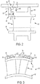
- the gas turbine engine 10 includes a compressor section 12, a combustor section 14, and a turbine section 16 that are disposed within a case assembly 18. Intake air is compressed by the compressor section 12 and is directed to the combustor section 14. Within the combustor section 14 the compressed air is heated. The heated compressed air is directed to the turbine section 16 where the energy is extracted by a plurality of turbine blades of the turbine section 16.
- the case assembly 18 extends about the compressor section 12, the combustor section 14, and the turbine section 16.
- the case assembly 18 may include a plurality of cases 30 that are joined together.
- the plurality of cases 30 that are joined together may have varying configurations to accommodate a respective section of the gas turbine engine 10.
- a case of the plurality of cases 30 includes a mounting feature 32.
- the mounting feature 32 is configured as a rail having a hooked portion that extends circumferentially about an inner surface of a case of the plurality of cases 30.
- the mounting feature 32 extends from the case and includes a first mounting feature portion 34 and a second mounting feature portion 36.
- the first mounting feature portion 34 is disposed substantially perpendicular to the case.
- the second mounting feature portion 36 extends from the first mounting feature portion 34.
- the second mounting feature portion 36 is disposed substantially perpendicular to the first mounting feature portion 34.
- the second mounting feature portion 36 is disposed substantially parallel to the case.
- the second mounting feature 34 may have a curvilinear shape when viewed in cross-section that has a radius of curvature substantially similar to the curvature of the case.
- the intake air that is compressed, heated and directed to the plurality of turbine blades by at least one vane assembly 40 The vane assembly 40 may be configured as a turbine vane assembly or a compressor vane assembly.
- the vane assembly 40 has a first end 42 and a second end 44.
- the vane assembly 40 is connected to the case by the mounting feature 32 at the first end 42.
- the vane assembly 40 includes an outer platform 50, an inner platform 52, a vane 54, and the seal 56.
- the outer platform 50 is disposed proximate the case.
- the inner platform 52 is spaced apart from and is disposed opposite the outer platform 50.
- the vane 54 is configured as an airfoil that extends between the outer platform 50 and the inner platform 52.
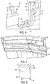
- the outer platform 50 includes a first rail 60 and a second rail 62.
- the first rail 60 extends from the outer platform 50 towards the case.
- the first rail 60 is disposed proximate the first end 42 of the vane assembly 40.
- the first rail 60 acts as a pressure wall that takes a pressure drop across the vane assembly 40.
- the first rail 60 includes a first face 70, a second face 72, a first rail member 74, a second rail member 76, a first opening 78, a second opening 80, and a slotted region 82.
- the first face 70 extends from an end of the first rail 60 disposed proximate the outer platform 50 towards and end of the first rail 60 disposed proximate the case.
- the second face 72 is disposed opposite the first face 70.
- the second face 72 is disposed substantially parallel to the first face 70.
- the first rail member 74 extends from the first face 70 towards the mounting feature 32.
- the first rail member 74 is disposed substantially perpendicular to the first face 70.
- the first rail member 74, the first face 70, and a portion of the outer platform 50 define an opening 90.
- the opening 90 is configured to receive at least a portion of the second mounting feature portion 36 of the mounting feature 32 to mount the vane assembly 40 to the case of the plurality of cases 30.
- the second rail member 76 is radially spaced apart from the first rail member 74.
- the second rail member 76 extends from the first face 70 towards the mounting feature 32.
- the second rail member 76, the first face 70, and a portion of the outer platform 50 define another opening 92.
- the another opening 92 is configured to receive at least a portion of the second mounting feature portion 36 of the mounting feature 32 to mount the vane assembly 40 to the case of the plurality of cases 30.
- the first opening 78 is disposed between the first rail member 74 and the second rail member 76.
- the first opening 78 is defined by the first rail 60.
- the first opening 78 extends from the first face 70 towards the second face 72.
- the first opening 78 extends from the first face 70 towards a first support surface 100, a second support surface 102, and a third support surface 104.
- the first support surface 100 and the second support surface 102 are spaced apart from each other by the first opening 78.
- the third support surface 104 extends between the first support surface 100 and the second support surface 102.
- the first support surface 100, the second support surface 102, and the third support surface 104 are disposed between the first face 70 and the second face 72.
- the first support surface 100, the second support surface 102, and the third support surface 104 are disposed substantially parallel to the first face 70 and the second face 72.
- the first opening 78 includes a first side surface 110, a second side surface 112, and a first opening surface 114.
- the first side surface 110 extends from the first face 70 to the first support surface 100.
- the second side surface 112 is disposed opposite the first side surface 110.
- the second side surface 112 extends from the first face 70 to the second support surface 102.
- the first opening surface 114 extends between the first side surface 110 and the second side surface 112.
- the first opening surface 114 extends from the first face 70 to the third support surface 104.
- the first opening 78 has a first width.
- the second opening 80 is disposed between the first rail member 74 and the second rail member 76.
- the second opening 80 is disposed substantially co-linearly or coaxially with the first opening 78.
- the second opening 80 is defined by the first rail 60.
- the second opening 80 extends from the second face 72 towards the first face 70.
- the second opening 80 extends from the second face 72 towards a fourth support surface 120, a fifth support surface 122, and a sixth support surface 124.
- the fourth support surface 120 and the fifth support surface 122 are spaced apart from each other by the second opening 80.
- the sixth support surface 124 extends between the fourth support surface 120 and the fifth support surface 122.
- the fourth support surface 120, the fifth support surface 122, and the sixth support surface 124 disposed between the second face 72 and the first face 70.
- the fourth support surface 120, the fifth support surface 122, and the sixth support surface 124 are spaced apart from the first support surface 100, the second support surface 102, and the third support surface 104.
- the fourth support surface 120, the fifth support surface 122, and the sixth support surface 124 are disposed substantially parallel to the first support surface 100, the second support surface 102, and the third support surface 104.
- the fourth support surface 120, the fifth support surface 122, and the sixth support surface 124 are disposed substantially parallel to the second face 72 and the first face 70.
- the second opening 80 includes a third side surface 130, a fourth side surface 132, and a second opening surface 134.
- the third side surface 130 extends from the second face 72 to the fourth support surface 120.
- the fourth side surface 132 is disposed opposite the third side surface 130.
- the fourth side surface 132 extends from the second face 72 to the fifth support surface 122.
- the second opening surface 134 extends between the third side surface 130 and the fourth side surface 132.
- the second opening surface 134 extends from the second face 72 to the sixth support surface 124.
- the second opening 80 has a second width. The second width is less than the first width.
- the first opening 78 is spaced apart from the second opening 80 by the slotted region 82.
- Slotted region 82 is defined between the first support surface 100, the second support surface 102, the third support surface 104, the fourth support surface 120, the fifth support surface 122, and the sixth support surface 124.
- the slotted region 82 has a slotted region width that is greater than the first width.
- the first opening 78 and the second opening 80 lowers stresses that are experienced by the vane assembly 40.
- the first opening 78 and the second opening 80 reduces stresses between a fillet that extends between the outer platform 50 and the vane 54 to connect the outer platform 50 to the vane 54.
- the first opening 78 and the second opening 80 soften the first rail 60 to reduce stresses.
- the second rail 62 is disposed proximate the second end 44 of the vane assembly 40.
- the second rail 62 extends from the outer platform 50 towards the case.
- the second rail 62 may be provided with the first opening 78, the second opening 80, and the slotted region 82 disposed between the first opening 78 and the second opening 80.
- the first opening 78, the second opening 80, and the slotted region 82 may have a substantially similar configuration as previously described..
- the seal 56 is received within the slotted region 82 that is disposed between the first opening 78 and the second opening 80 of at least one of the first rail 60 and the second rail 62.
- the seal 56 includes a seal body 140.
- the seal body 140 extends between a first seal face 142 and a second seal face 144.
- the first seal face 142 engages the first support surface 100, the second support surface 102, and the third support surface 104.
- the second seal face 144 engages the fourth support surface 120, the fifth support surface 122, and the sixth support surface 124.
- the seal body 140 extends between a first seal end 146 and a second seal end 148.
- the first seal end 146 is disposed proximate the outer platform 50.
- the second seal end 148 is disposed opposite the first seal end 146.
- the second seal end 148 includes a curved portion 150.
- the curved portion 150 curves towards the first face 70.
- the curved portion 150 has an arcuate profile and extends at least partially over the first opening 78.
- attachment shall be interpreted to mean that a structural component or element is in some manner connected to or contacts another element, either directly or indirectly through at least one intervening structural element, or is integrally formed with the other structural element.
Landscapes
- Engineering & Computer Science (AREA)
- Mechanical Engineering (AREA)
- General Engineering & Computer Science (AREA)
- Turbine Rotor Nozzle Sealing (AREA)
Claims (3)
- Gasturbinenmotor (10), umfassend:ein Gehäuse (30); undeine Leitschaufelanordnung (40), die mit dem Gehäuse verbunden ist, wobei die Leitschaufelanordnung Folgendes umfasst:eine äußere Plattform (50), die nahe dem Gehäuse angeordnet ist, wobei die äußere Plattform eine erste Schiene (60) aufweist, die sich in Richtung des Gehäuses erstreckt, wobei die erste Schiene eine erste Fläche (70), eine gegenüber der ersten Fläche angeordnete zweite Fläche (72) und eine erste Öffnung (78), die sich von der ersten Fläche in Richtung der zweiten Fläche erstreckt, aufweist,eine innere Plattform (52), die gegenüber der äußeren Plattform angeordnet ist, undeine Leitschaufel (54), die sich zwischen der inneren Plattform und der äußeren Plattform erstreckt,wobei die erste Öffnung (78) ein erste Seitenfläche (110), die sich von der ersten Fläche (70) in Richtung einer ersten Auflagefläche (100) erstreckt, eine gegenüber der ersten Seitenfläche angeordnete zweite Seitenfläche (112), die sich von der ersten Fläche in Richtung einer zweiten Auflagefläche (102) erstreckt, und eine erste Öffnungsfläche (114), die sich zwischen der ersten Seitenfläche und der zweiten Seitenfläche erstreckt, beinhaltet, wobei sich die erste Öffnungsfläche von der ersten Fläche in Richtung einer dritten Auflagefläche (104) erstreckt, die sich zwischen der ersten Auflagefläche und der zweiten Auflagefläche erstreckt, wobei die erste Schiene (60) eine zweite Öffnung (80) definiert, die sich von der zweiten Fläche (72) in Richtung der ersten Fläche (70) erstreckt, wobei die zweite Öffnung (80) eine dritte Seitenfläche (130), die sich von der zweiten Fläche (72) in Richtung einer vierten Auflagefläche (120) erstreckt, eine gegenüber der dritten Seitenfläche angeordnete vierte Seitenfläche (132), die sich von der zweiten Fläche in Richtung einer fünften Auflagefläche (122) erstreckt, und eine zweite Öffnungsfläche (134), die sich von der zweiten Fläche in Richtung einer sechsten Auflagefläche (124) erstreckt, beinhaltet,wobei der Gasturbinenmotor (10) ferner eine Dichtung (56) umfasst, die innerhalb eines geschlitzten Bereichs (82) aufgenommen ist, der zwischen der ersten Auflagefläche (100), der zweiten Auflagefläche (102), der dritten Auflagefläche (104), der vierten Auflagefläche (120), der fünften Auflagefläche (122) und der sechsten Auflagefläche (124) angeordnet ist,wobei die Dichtung (56) einen Dichtungskörper (140) aufweist, der sich zwischen einer ersten Dichtungsfläche (142) und einer zweiten Dichtungsfläche (144) erstreckt,wobeidie Dichtung (56) einen gekrümmten Abschnitt beinhaltet, der sich in Richtung der ersten Fläche krümmt,dadurch gekennzeichnet, dassdie erste Dichtungsfläche die erste Auflagefläche (100), die zweite Auflagefläche (102) und die dritte Auflagefläche (104) in Eingriff nimmt und die zweite Dichtungsfläche die vierte Auflagefläche (120), die fünfte Auflagefläche (122) und die sechste Auflagefläche (124) in Eingriff nimmt, unddie erste Öffnung (78) eine erste Breite aufweist, die zwischen der ersten Seitenfläche und der zweiten Seitenfläche definiert ist, und die zweite Öffnung (80) eine zweite Breite aufweist, die zwischen der dritten Seitenfläche und der vierten Seitenfläche definiert ist, wobei die zweite Breite geringer als die erste Breite ist.
- Gasturbinenmotor (10) nach Anspruch 1, wobei das Gehäuse (30) ein Befestigungsmerkmal (32) beinhaltet, wobei das Befestigungsmerkmal einen ersten Befestigungsmerkmalsabschnitt (34), der sich von dem Gehäuse erstreckt, und einen zweiten Befestigungsmerkmalsabschnitt (36), der senkrecht zu dem ersten Befestigungsmerkmalsabschnitt angeordnet ist und sich in Richtung der ersten Schiene (60) erstreckt, aufweist.
- Gasturbinenmotor (10) nach Anspruch 2, wobei die erste Schiene (60) ein Schienenbauteil (74) aufweist, das sich von der ersten Fläche (70) in Richtung des Befestigungsmerkmals (32) erstreckt, wobei der zweite Befestigungsmerkmalsabschnitt (36) vorzugsweise zwischen dem Schienenbauteil (74) und der äußeren Plattform (50) angeordnet ist.
Applications Claiming Priority (1)
| Application Number | Priority Date | Filing Date | Title |
|---|---|---|---|
| US15/147,954 US10385705B2 (en) | 2016-05-06 | 2016-05-06 | Gas turbine engine having a vane assembly |
Publications (3)
| Publication Number | Publication Date |
|---|---|
| EP3244020A2 EP3244020A2 (de) | 2017-11-15 |
| EP3244020A3 EP3244020A3 (de) | 2018-05-16 |
| EP3244020B1 true EP3244020B1 (de) | 2020-05-06 |
Family
ID=58231535
Family Applications (1)
| Application Number | Title | Priority Date | Filing Date |
|---|---|---|---|
| EP17159421.1A Active EP3244020B1 (de) | 2016-05-06 | 2017-03-06 | Gasturbinenmotor mit einer leitschaufelanordnung |
Country Status (2)
| Country | Link |
|---|---|
| US (1) | US10385705B2 (de) |
| EP (1) | EP3244020B1 (de) |
Families Citing this family (4)
| Publication number | Priority date | Publication date | Assignee | Title |
|---|---|---|---|---|
| FR3111162B1 (fr) * | 2020-06-04 | 2022-06-24 | Safran Aircraft Engines | Soudure avec languette d’étanchéité |
| JP2021195920A (ja) | 2020-06-16 | 2021-12-27 | 東芝エネルギーシステムズ株式会社 | タービン静翼 |
| US11814991B1 (en) * | 2022-07-28 | 2023-11-14 | General Electric Company | Turbine nozzle assembly with stress relief structure for mounting rail |
| US11885241B1 (en) | 2022-07-28 | 2024-01-30 | General Electric Company | Turbine nozzle assembly with stress relief structure for mounting rail |
Family Cites Families (8)
| Publication number | Priority date | Publication date | Assignee | Title |
|---|---|---|---|---|
| US2462268A (en) * | 1947-05-01 | 1949-02-22 | Kahi Joseph | Locking means for a hinged impact mass or weight for marine equipment |
| US7524163B2 (en) | 2003-12-12 | 2009-04-28 | Rolls-Royce Plc | Nozzle guide vanes |
| US7293957B2 (en) * | 2004-07-14 | 2007-11-13 | Power Systems Mfg., Llc | Vane platform rail configuration for reduced airfoil stress |
| US7762761B2 (en) | 2005-11-30 | 2010-07-27 | General Electric Company | Methods and apparatus for assembling turbine nozzles |
| US7958735B2 (en) * | 2006-12-21 | 2011-06-14 | Power Systems Manufacturing, Llc | Turbine static structure for reduced leakage air |
| GB2462268A (en) | 2008-07-30 | 2010-02-03 | Siemens Ag | A segment of an annular guide vane assembly comprising a cut-out with a seal block within |
| US10822980B2 (en) | 2013-04-11 | 2020-11-03 | Raytheon Technologies Corporation | Gas turbine engine stress isolation scallop |
| JP5717904B1 (ja) | 2014-08-04 | 2015-05-13 | 三菱日立パワーシステムズ株式会社 | 静翼、ガスタービン、分割環、静翼の改造方法、および、分割環の改造方法 |
-
2016
- 2016-05-06 US US15/147,954 patent/US10385705B2/en active Active
-
2017
- 2017-03-06 EP EP17159421.1A patent/EP3244020B1/de active Active
Non-Patent Citations (1)
| Title |
|---|
| None * |
Also Published As
| Publication number | Publication date |
|---|---|
| EP3244020A2 (de) | 2017-11-15 |
| EP3244020A3 (de) | 2018-05-16 |
| US20170321560A1 (en) | 2017-11-09 |
| US10385705B2 (en) | 2019-08-20 |
Similar Documents
| Publication | Publication Date | Title |
|---|---|---|
| US9951639B2 (en) | Vane assemblies for gas turbine engines | |
| EP2093383B1 (de) | Leitschaufel und Leitschaufelanordnung | |
| EP3244020B1 (de) | Gasturbinenmotor mit einer leitschaufelanordnung | |
| EP1762703B1 (de) | Fremdkörperschaden-resistente Leitschaufelanordnung | |
| US9556741B2 (en) | Shrouded blade for a gas turbine engine | |
| US9458720B2 (en) | Airfoil and platform assembly for supersonic flow | |
| EP3269938A1 (de) | System und verfahren für leitschaufelabdeckungsanordnung mit reduzierter spannung | |
| CA2622013C (en) | Vane assembly with grommet | |
| US9631500B2 (en) | Bucket assembly for use in a turbine engine | |
| WO2013166284A1 (en) | Shaped rim cavity wing surface | |
| US20130333350A1 (en) | Airfoil including adhesively bonded shroud | |
| JP5173625B2 (ja) | 動翼およびガスタービン | |
| US10385700B2 (en) | Turbomachine turbine blade squealer tip | |
| JP2021050734A (ja) | ターボ機械のブレード | |
| US9816379B2 (en) | Balancing body for a continuous blade arrangement | |
| KR102579644B1 (ko) | 터보 기계류 회전자 블레이드 | |
| US20120237358A1 (en) | Turbine blade tip | |
| US11280204B2 (en) | Air flow straightening assembly and turbomachine including such an assembly | |
| KR20160097271A (ko) | 블레이드 로터 | |
| EP2617948A2 (de) | Dichtung in der Nähe des Durchflusswegs für eine Turbomaschine | |
| US11035238B2 (en) | Airfoil including adhesively bonded shroud | |
| JP5449455B2 (ja) | 動翼 | |
| US9951631B2 (en) | Turbomachine rotor blade | |
| US8690530B2 (en) | System and method for supporting a nozzle assembly |
Legal Events
| Date | Code | Title | Description |
|---|---|---|---|
| PUAI | Public reference made under article 153(3) epc to a published international application that has entered the european phase |
Free format text: ORIGINAL CODE: 0009012 |
|
| STAA | Information on the status of an ep patent application or granted ep patent |
Free format text: STATUS: THE APPLICATION HAS BEEN PUBLISHED |
|
| AK | Designated contracting states |
Kind code of ref document: A2 Designated state(s): AL AT BE BG CH CY CZ DE DK EE ES FI FR GB GR HR HU IE IS IT LI LT LU LV MC MK MT NL NO PL PT RO RS SE SI SK SM TR |
|
| AX | Request for extension of the european patent |
Extension state: BA ME |
|
| PUAL | Search report despatched |
Free format text: ORIGINAL CODE: 0009013 |
|
| AK | Designated contracting states |
Kind code of ref document: A3 Designated state(s): AL AT BE BG CH CY CZ DE DK EE ES FI FR GB GR HR HU IE IS IT LI LT LU LV MC MK MT NL NO PL PT RO RS SE SI SK SM TR |
|
| AX | Request for extension of the european patent |
Extension state: BA ME |
|
| RIC1 | Information provided on ipc code assigned before grant |
Ipc: F01D 11/00 20060101AFI20180406BHEP Ipc: F01D 25/24 20060101ALI20180406BHEP Ipc: F01D 9/04 20060101ALI20180406BHEP |
|
| STAA | Information on the status of an ep patent application or granted ep patent |
Free format text: STATUS: REQUEST FOR EXAMINATION WAS MADE |
|
| 17P | Request for examination filed |
Effective date: 20181115 |
|
| RBV | Designated contracting states (corrected) |
Designated state(s): AL AT BE BG CH CY CZ DE DK EE ES FI FR GB GR HR HU IE IS IT LI LT LU LV MC MK MT NL NO PL PT RO RS SE SI SK SM TR |
|
| STAA | Information on the status of an ep patent application or granted ep patent |
Free format text: STATUS: EXAMINATION IS IN PROGRESS |
|
| 17Q | First examination report despatched |
Effective date: 20190311 |
|
| GRAP | Despatch of communication of intention to grant a patent |
Free format text: ORIGINAL CODE: EPIDOSNIGR1 |
|
| STAA | Information on the status of an ep patent application or granted ep patent |
Free format text: STATUS: GRANT OF PATENT IS INTENDED |
|
| INTG | Intention to grant announced |
Effective date: 20191122 |
|
| GRAS | Grant fee paid |
Free format text: ORIGINAL CODE: EPIDOSNIGR3 |
|
| GRAA | (expected) grant |
Free format text: ORIGINAL CODE: 0009210 |
|
| STAA | Information on the status of an ep patent application or granted ep patent |
Free format text: STATUS: THE PATENT HAS BEEN GRANTED |
|
| AK | Designated contracting states |
Kind code of ref document: B1 Designated state(s): AL AT BE BG CH CY CZ DE DK EE ES FI FR GB GR HR HU IE IS IT LI LT LU LV MC MK MT NL NO PL PT RO RS SE SI SK SM TR |
|
| REG | Reference to a national code |
Ref country code: GB Ref legal event code: FG4D |
|
| REG | Reference to a national code |
Ref country code: CH Ref legal event code: EP Ref country code: AT Ref legal event code: REF Ref document number: 1267041 Country of ref document: AT Kind code of ref document: T Effective date: 20200515 |
|
| REG | Reference to a national code |
Ref country code: IE Ref legal event code: FG4D |
|
| REG | Reference to a national code |
Ref country code: DE Ref legal event code: R096 Ref document number: 602017015942 Country of ref document: DE |
|
| REG | Reference to a national code |
Ref country code: LT Ref legal event code: MG4D |
|
| REG | Reference to a national code |
Ref country code: NL Ref legal event code: MP Effective date: 20200506 |
|
| PG25 | Lapsed in a contracting state [announced via postgrant information from national office to epo] |
Ref country code: IS Free format text: LAPSE BECAUSE OF FAILURE TO SUBMIT A TRANSLATION OF THE DESCRIPTION OR TO PAY THE FEE WITHIN THE PRESCRIBED TIME-LIMIT Effective date: 20200906 Ref country code: PT Free format text: LAPSE BECAUSE OF FAILURE TO SUBMIT A TRANSLATION OF THE DESCRIPTION OR TO PAY THE FEE WITHIN THE PRESCRIBED TIME-LIMIT Effective date: 20200907 Ref country code: LT Free format text: LAPSE BECAUSE OF FAILURE TO SUBMIT A TRANSLATION OF THE DESCRIPTION OR TO PAY THE FEE WITHIN THE PRESCRIBED TIME-LIMIT Effective date: 20200506 Ref country code: FI Free format text: LAPSE BECAUSE OF FAILURE TO SUBMIT A TRANSLATION OF THE DESCRIPTION OR TO PAY THE FEE WITHIN THE PRESCRIBED TIME-LIMIT Effective date: 20200506 Ref country code: SE Free format text: LAPSE BECAUSE OF FAILURE TO SUBMIT A TRANSLATION OF THE DESCRIPTION OR TO PAY THE FEE WITHIN THE PRESCRIBED TIME-LIMIT Effective date: 20200506 Ref country code: NO Free format text: LAPSE BECAUSE OF FAILURE TO SUBMIT A TRANSLATION OF THE DESCRIPTION OR TO PAY THE FEE WITHIN THE PRESCRIBED TIME-LIMIT Effective date: 20200806 Ref country code: GR Free format text: LAPSE BECAUSE OF FAILURE TO SUBMIT A TRANSLATION OF THE DESCRIPTION OR TO PAY THE FEE WITHIN THE PRESCRIBED TIME-LIMIT Effective date: 20200807 |
|
| PG25 | Lapsed in a contracting state [announced via postgrant information from national office to epo] |
Ref country code: BG Free format text: LAPSE BECAUSE OF FAILURE TO SUBMIT A TRANSLATION OF THE DESCRIPTION OR TO PAY THE FEE WITHIN THE PRESCRIBED TIME-LIMIT Effective date: 20200806 Ref country code: RS Free format text: LAPSE BECAUSE OF FAILURE TO SUBMIT A TRANSLATION OF THE DESCRIPTION OR TO PAY THE FEE WITHIN THE PRESCRIBED TIME-LIMIT Effective date: 20200506 Ref country code: LV Free format text: LAPSE BECAUSE OF FAILURE TO SUBMIT A TRANSLATION OF THE DESCRIPTION OR TO PAY THE FEE WITHIN THE PRESCRIBED TIME-LIMIT Effective date: 20200506 Ref country code: HR Free format text: LAPSE BECAUSE OF FAILURE TO SUBMIT A TRANSLATION OF THE DESCRIPTION OR TO PAY THE FEE WITHIN THE PRESCRIBED TIME-LIMIT Effective date: 20200506 |
|
| REG | Reference to a national code |
Ref country code: AT Ref legal event code: MK05 Ref document number: 1267041 Country of ref document: AT Kind code of ref document: T Effective date: 20200506 |
|
| PG25 | Lapsed in a contracting state [announced via postgrant information from national office to epo] |
Ref country code: AL Free format text: LAPSE BECAUSE OF FAILURE TO SUBMIT A TRANSLATION OF THE DESCRIPTION OR TO PAY THE FEE WITHIN THE PRESCRIBED TIME-LIMIT Effective date: 20200506 Ref country code: NL Free format text: LAPSE BECAUSE OF FAILURE TO SUBMIT A TRANSLATION OF THE DESCRIPTION OR TO PAY THE FEE WITHIN THE PRESCRIBED TIME-LIMIT Effective date: 20200506 |
|
| PG25 | Lapsed in a contracting state [announced via postgrant information from national office to epo] |
Ref country code: EE Free format text: LAPSE BECAUSE OF FAILURE TO SUBMIT A TRANSLATION OF THE DESCRIPTION OR TO PAY THE FEE WITHIN THE PRESCRIBED TIME-LIMIT Effective date: 20200506 Ref country code: SM Free format text: LAPSE BECAUSE OF FAILURE TO SUBMIT A TRANSLATION OF THE DESCRIPTION OR TO PAY THE FEE WITHIN THE PRESCRIBED TIME-LIMIT Effective date: 20200506 Ref country code: DK Free format text: LAPSE BECAUSE OF FAILURE TO SUBMIT A TRANSLATION OF THE DESCRIPTION OR TO PAY THE FEE WITHIN THE PRESCRIBED TIME-LIMIT Effective date: 20200506 Ref country code: IT Free format text: LAPSE BECAUSE OF FAILURE TO SUBMIT A TRANSLATION OF THE DESCRIPTION OR TO PAY THE FEE WITHIN THE PRESCRIBED TIME-LIMIT Effective date: 20200506 Ref country code: RO Free format text: LAPSE BECAUSE OF FAILURE TO SUBMIT A TRANSLATION OF THE DESCRIPTION OR TO PAY THE FEE WITHIN THE PRESCRIBED TIME-LIMIT Effective date: 20200506 Ref country code: AT Free format text: LAPSE BECAUSE OF FAILURE TO SUBMIT A TRANSLATION OF THE DESCRIPTION OR TO PAY THE FEE WITHIN THE PRESCRIBED TIME-LIMIT Effective date: 20200506 Ref country code: CZ Free format text: LAPSE BECAUSE OF FAILURE TO SUBMIT A TRANSLATION OF THE DESCRIPTION OR TO PAY THE FEE WITHIN THE PRESCRIBED TIME-LIMIT Effective date: 20200506 Ref country code: ES Free format text: LAPSE BECAUSE OF FAILURE TO SUBMIT A TRANSLATION OF THE DESCRIPTION OR TO PAY THE FEE WITHIN THE PRESCRIBED TIME-LIMIT Effective date: 20200506 |
|
| REG | Reference to a national code |
Ref country code: DE Ref legal event code: R097 Ref document number: 602017015942 Country of ref document: DE |
|
| PG25 | Lapsed in a contracting state [announced via postgrant information from national office to epo] |
Ref country code: PL Free format text: LAPSE BECAUSE OF FAILURE TO SUBMIT A TRANSLATION OF THE DESCRIPTION OR TO PAY THE FEE WITHIN THE PRESCRIBED TIME-LIMIT Effective date: 20200506 Ref country code: SK Free format text: LAPSE BECAUSE OF FAILURE TO SUBMIT A TRANSLATION OF THE DESCRIPTION OR TO PAY THE FEE WITHIN THE PRESCRIBED TIME-LIMIT Effective date: 20200506 |
|
| PLBE | No opposition filed within time limit |
Free format text: ORIGINAL CODE: 0009261 |
|
| STAA | Information on the status of an ep patent application or granted ep patent |
Free format text: STATUS: NO OPPOSITION FILED WITHIN TIME LIMIT |
|
| RAP2 | Party data changed (patent owner data changed or rights of a patent transferred) |
Owner name: RAYTHEON TECHNOLOGIES CORPORATION |
|
| 26N | No opposition filed |
Effective date: 20210209 |
|
| PG25 | Lapsed in a contracting state [announced via postgrant information from national office to epo] |
Ref country code: SI Free format text: LAPSE BECAUSE OF FAILURE TO SUBMIT A TRANSLATION OF THE DESCRIPTION OR TO PAY THE FEE WITHIN THE PRESCRIBED TIME-LIMIT Effective date: 20200506 |
|
| PG25 | Lapsed in a contracting state [announced via postgrant information from national office to epo] |
Ref country code: MC Free format text: LAPSE BECAUSE OF FAILURE TO SUBMIT A TRANSLATION OF THE DESCRIPTION OR TO PAY THE FEE WITHIN THE PRESCRIBED TIME-LIMIT Effective date: 20200506 |
|
| REG | Reference to a national code |
Ref country code: CH Ref legal event code: PL |
|
| REG | Reference to a national code |
Ref country code: BE Ref legal event code: MM Effective date: 20210331 |
|
| PG25 | Lapsed in a contracting state [announced via postgrant information from national office to epo] |
Ref country code: LI Free format text: LAPSE BECAUSE OF NON-PAYMENT OF DUE FEES Effective date: 20210331 Ref country code: LU Free format text: LAPSE BECAUSE OF NON-PAYMENT OF DUE FEES Effective date: 20210306 Ref country code: CH Free format text: LAPSE BECAUSE OF NON-PAYMENT OF DUE FEES Effective date: 20210331 Ref country code: IE Free format text: LAPSE BECAUSE OF NON-PAYMENT OF DUE FEES Effective date: 20210306 |
|
| PG25 | Lapsed in a contracting state [announced via postgrant information from national office to epo] |
Ref country code: BE Free format text: LAPSE BECAUSE OF NON-PAYMENT OF DUE FEES Effective date: 20210331 |
|
| REG | Reference to a national code |
Ref country code: DE Ref legal event code: R081 Ref document number: 602017015942 Country of ref document: DE Owner name: RAYTHEON TECHNOLOGIES CORPORATION (N.D.GES.D.S, US Free format text: FORMER OWNER: UNITED TECHNOLOGIES CORPORATION, FARMINGTON, CONN., US Ref country code: DE Ref legal event code: R081 Ref document number: 602017015942 Country of ref document: DE Owner name: RTX CORPORATION (N.D.GES.D. STAATES DELAWARE),, US Free format text: FORMER OWNER: UNITED TECHNOLOGIES CORPORATION, FARMINGTON, CONN., US |
|
| PG25 | Lapsed in a contracting state [announced via postgrant information from national office to epo] |
Ref country code: HU Free format text: LAPSE BECAUSE OF FAILURE TO SUBMIT A TRANSLATION OF THE DESCRIPTION OR TO PAY THE FEE WITHIN THE PRESCRIBED TIME-LIMIT; INVALID AB INITIO Effective date: 20170306 |
|
| P01 | Opt-out of the competence of the unified patent court (upc) registered |
Effective date: 20230520 |
|
| PG25 | Lapsed in a contracting state [announced via postgrant information from national office to epo] |
Ref country code: CY Free format text: LAPSE BECAUSE OF FAILURE TO SUBMIT A TRANSLATION OF THE DESCRIPTION OR TO PAY THE FEE WITHIN THE PRESCRIBED TIME-LIMIT Effective date: 20200506 |
|
| PG25 | Lapsed in a contracting state [announced via postgrant information from national office to epo] |
Ref country code: MK Free format text: LAPSE BECAUSE OF FAILURE TO SUBMIT A TRANSLATION OF THE DESCRIPTION OR TO PAY THE FEE WITHIN THE PRESCRIBED TIME-LIMIT Effective date: 20200506 |
|
| PG25 | Lapsed in a contracting state [announced via postgrant information from national office to epo] |
Ref country code: TR Free format text: LAPSE BECAUSE OF FAILURE TO SUBMIT A TRANSLATION OF THE DESCRIPTION OR TO PAY THE FEE WITHIN THE PRESCRIBED TIME-LIMIT Effective date: 20200506 |
|
| PG25 | Lapsed in a contracting state [announced via postgrant information from national office to epo] |
Ref country code: MT Free format text: LAPSE BECAUSE OF FAILURE TO SUBMIT A TRANSLATION OF THE DESCRIPTION OR TO PAY THE FEE WITHIN THE PRESCRIBED TIME-LIMIT Effective date: 20200506 |
|
| REG | Reference to a national code |
Ref country code: DE Ref legal event code: R081 Ref document number: 602017015942 Country of ref document: DE Owner name: RTX CORPORATION (N.D.GES.D. STAATES DELAWARE),, US Free format text: FORMER OWNER: RAYTHEON TECHNOLOGIES CORPORATION (N.D.GES.D.STAATES DELAWARE), ARLINGTON, VA, US |
|
| PGFP | Annual fee paid to national office [announced via postgrant information from national office to epo] |
Ref country code: GB Payment date: 20260219 Year of fee payment: 10 |
|
| PGFP | Annual fee paid to national office [announced via postgrant information from national office to epo] |
Ref country code: DE Payment date: 20260219 Year of fee payment: 10 |
|
| PGFP | Annual fee paid to national office [announced via postgrant information from national office to epo] |
Ref country code: FR Payment date: 20260219 Year of fee payment: 10 |