EP3244067A1 - Pompe à vide et procédé de réduction d'un balourd residuel dans une pompe à vide - Google Patents
Pompe à vide et procédé de réduction d'un balourd residuel dans une pompe à vide Download PDFInfo
- Publication number
- EP3244067A1 EP3244067A1 EP16168947.6A EP16168947A EP3244067A1 EP 3244067 A1 EP3244067 A1 EP 3244067A1 EP 16168947 A EP16168947 A EP 16168947A EP 3244067 A1 EP3244067 A1 EP 3244067A1
- Authority
- EP
- European Patent Office
- Prior art keywords
- rotor shaft
- rotor
- vacuum pump
- stator
- electric motor
- Prior art date
- Legal status (The legal status is an assumption and is not a legal conclusion. Google has not performed a legal analysis and makes no representation as to the accuracy of the status listed.)
- Granted
Links
Images


Classifications
-
- F—MECHANICAL ENGINEERING; LIGHTING; HEATING; WEAPONS; BLASTING
- F04—POSITIVE - DISPLACEMENT MACHINES FOR LIQUIDS; PUMPS FOR LIQUIDS OR ELASTIC FLUIDS
- F04D—NON-POSITIVE-DISPLACEMENT PUMPS
- F04D19/00—Axial-flow pumps
- F04D19/02—Multi-stage pumps
- F04D19/04—Multi-stage pumps specially adapted to the production of a high vacuum, e.g. molecular pumps
- F04D19/042—Turbomolecular vacuum pumps
-
- F—MECHANICAL ENGINEERING; LIGHTING; HEATING; WEAPONS; BLASTING
- F04—POSITIVE - DISPLACEMENT MACHINES FOR LIQUIDS; PUMPS FOR LIQUIDS OR ELASTIC FLUIDS
- F04D—NON-POSITIVE-DISPLACEMENT PUMPS
- F04D19/00—Axial-flow pumps
- F04D19/02—Multi-stage pumps
- F04D19/04—Multi-stage pumps specially adapted to the production of a high vacuum, e.g. molecular pumps
- F04D19/046—Combinations of two or more different types of pumps
-
- F—MECHANICAL ENGINEERING; LIGHTING; HEATING; WEAPONS; BLASTING
- F04—POSITIVE - DISPLACEMENT MACHINES FOR LIQUIDS; PUMPS FOR LIQUIDS OR ELASTIC FLUIDS
- F04D—NON-POSITIVE-DISPLACEMENT PUMPS
- F04D29/00—Details, component parts, or accessories
- F04D29/66—Combating cavitation, whirls, noise, vibration or the like; Balancing
- F04D29/661—Combating cavitation, whirls, noise, vibration or the like; Balancing especially adapted for elastic fluid pumps
- F04D29/662—Balancing of rotors
Definitions
- the present invention relates to a vacuum pump, in particular a turbomolecular pump, having a rotor shaft rotatable about a rotation axis and an electric motor comprising a stator fixed to a housing of the vacuum pump and a rotor coupled to the rotor shaft, wherein the stator and the rotor for rotatably driving the rotor shaft are provided.
- the present invention also relates to a method for reducing residual imbalance of a rotor shaft of a vacuum pump, in particular turbomolecular pump, which is rotatable about a rotation axis.
- a vacuum pump of the type mentioned is basically known.
- the rotor shaft is normally balanced before the vacuum pump is put into operation, in particular to reduce the risk of damage to the rotor shaft and to the bearings of the rotor shaft.
- a so-called residual imbalance remains, which according to DIN ISO 1925: 2001 is an imbalance of any kind which remains after balancing.
- the balancing operation can reduce an initial initial imbalance of the rotor shaft, which according to the cited standard is an imbalance of any kind present in the rotor before balancing, to a residual residual imbalance. With the residual imbalance, the vacuum pump can normally be put into operation without problems.
- the residual imbalance is based in particular on a mass defect on the rotor shaft, which can be described as a punctiform mass m at a distance r from the axis of rotation of the rotor shaft.
- a vacuum pump according to the preamble of claim 1 and a method for balancing a rotor of a vacuum pump are described in US 5,256,066 EP 2 881 591 A2 disclosed.
- the present invention is therefore based on the object to reduce a residual imbalance of a rotor shaft of a vacuum pump.
- a vacuum pump comprises a rotor shaft rotatable about a rotation axis and an electric motor having a stator fixed to a housing of the vacuum pump and a rotor coupled to the rotor shaft, wherein the stator and the rotor are provided for rotationally driving the rotor shaft, wherein the electric motor, in particular its Stator, is designed such that this synchronously with the rotor shaft rotating, in particular acting in the radial direction, force on the rotor shaft, in particular on the rotor shaft coupled to the rotor causes, wherein by means of the force also synchronously circulating residual imbalance of the rotor shaft can be at least approximately compensated.
- the residual imbalance still present after balancing or the force F RU circulating in synchronism with the rotor shaft can thus be at least approximately compensated by the force generated by the electric motor during operation of the vacuum pump.
- the rotor shaft runs even less unbalanced, whereby the life of the rotor shaft and its bearings can be increased.
- a vacuum pump according to the invention thus has, in terms of unbalance, over a relatively long period of operation, the substantially same properties, such as an increase in the residual imbalance, for example, caused by wear in storage, at least to some extent by that of the electric motor generated force can be compensated.
- each vacuum pump according to the invention has at least approximately the same balancing state and thus the same state of vibration technology.
- the rotor of an electric motor is also referred to as an armature or rotor of the electric motor.
- a so-called PM synchronous motor is used as the electric motor, PM standing for permanent magnet.
- permanent magnets are arranged in the rotor, which form the rotor or rotor-side magnetic poles of the electric motor.
- the magnetic poles are realized by means of conductor windings.
- PM synchronous motors are known from the prior art.
- the vacuum pump preferably has at least one sensor, in particular an acceleration sensor, for measuring the residual imbalance of the rotor shaft.
- the residual imbalance can thus be measured during operation of the vacuum pump and the measured value obtained can be used, for example, to control the electric motor.
- the at least one sensor can be arranged in a plane which runs through the stator of the electric motor and at least substantially perpendicular to the rotor shaft.
- the residual imbalance can thus be detected in a running through the stator of the electric motor balancing plane and at least approximately compensated.
- the senor is arranged on the rotor of the electric motor.
- the sensor may alternatively be arranged slightly above or below the rotor on the rotor shaft. The residual unbalance can therefore be detected in the area of the electric motor.
- the at least one sensor can also be arranged in the region of a bearing which serves to support the rotor shaft.
- the detection of the residual imbalance in the area of the bearing has the advantage that this residual imbalance can be at least approximately compensated by means of the electric motor. As a result, damage to the bearing due to the residual imbalance can be avoided particularly effectively.
- At least one operating parameter of the electric motor for adjusting the force according to magnitude and / or phase position and / or for adjusting the rotational speed of the force about the axis of rotation is adjustable by means of a control.
- the force can thus be generated so that it rotates synchronously with the rotational speed of the rotor shaft and thus with the residual imbalance about the axis of rotation and thereby the residual imbalance at least approximately compensated.
- phase angle refers to the direction of the force with respect to the angular position of the rotor shaft.
- the phase position of the force is preferably adjusted so that the force of the residual imbalance is opposite.
- At least one alternating current which is fed into the electric motor can be adjusted so that the magnetic field generated between the stator and the rotor of the electric motor causes a resultant magnetic force on the rotor which is synchronous with the rotational speed of the rotor shaft and thus rotates with the residual imbalance about the axis of rotation while the residual imbalance at least approximately compensated, so at least approximately the amount of residual imbalance and this is opposite.
- Adjusting the alternating current may include adjusting the amplitude, adjusting the frequency, and / or adjusting the phase of the alternating current.
- the electric motor and / or a controller for the electric motor can be equipped with appropriate means for adjusting the amplitude, frequency and phase.
- the controller may be designed to iteratively adjust the at least one operating parameter of the electric motor depending on a residual imbalance of the rotor shaft, in particular until the residual imbalance meets a predetermined criterion, in particular assumes a minimum value or falls below a predetermined threshold.
- the at least one operating parameter of the electric motor and thus the force generated by the electric motor can be adjusted until the simultaneously measured residual imbalance meets the criterion.
- the stator - viewed in the circumferential direction of the stator - offset from each other auxiliary windings, and the controller can each of the auxiliary windings for generating a magnetic field with an electric Supply current, in particular an alternating current, to generate the force at least substantially by the interaction of the magnetic fields generated by the auxiliary windings with the magnetic field of the rotor of the electric motor.
- an electric Supply current in particular an alternating current
- It can thus be provided on the stator a plurality of energizable auxiliary windings with which respective magnetic fields can be generated, which interact with the rotor-side magnetic field.
- stator has four auxiliary windings which are arranged offset by at least approximately 90 degrees in the circumferential direction.
- Each auxiliary winding can be arranged on a pole shoe provided on the stator.
- the pole shoes can serve in particular as a carrier for the auxiliary windings.
- the control is preferably designed to adjust the currents through the auxiliary windings, in particular as a function of the respective angular position of the rotor shaft and / or as a function of a measured residual imbalance, in order to generate the force for at least approximately compensating the residual imbalance.
- the vacuum pump may have at least one sensor for measuring the angular position of the rotor shaft. This can be permanently detected during pump operation, the angular position of the rotor shaft.
- the vacuum pump is preferably a turbomolecular pump. Since the rotor shaft of a turbomolecular pump is normally operated at a very high speed, for example at a speed of several tens of thousands of revolutions per minute, the at least approximately compensated residual imbalance contributes, for example, to an extension of the life of the vacuum pump.
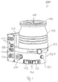
- turbomolecular pump 111 comprises a pump inlet 115 surrounded by an inlet flange 113, to which in a conventional manner, a non-illustrated recipient can be connected.
- the gas from the recipient may be drawn from the recipient via the pump inlet 115 and conveyed through the pump to a pump outlet 117 to which a backing pump, such as a rotary vane pump, may be connected.
- the inlet flange 113 forms according to the orientation of the vacuum pump Fig. 1 the upper end of the housing 119 of the vacuum pump 111.
- the housing 119 comprises a lower part 121, on which an electronics housing 123 is arranged laterally.
- Housed in the electronics housing 123 are electrical and / or electronic components of the vacuum pump 111, eg for operating an electric motor 125 arranged in the vacuum pump.
- a plurality of connections 127 for accessories are provided on the electronics housing 123. Besides, they are a data interface 129, for example, according to the RS485 standard, and a power supply terminal 131 arranged on the electronics housing 123.
- a flood inlet 133 On the housing 119 of the turbomolecular pump 111, a flood inlet 133, in particular in the form of a flood valve, is provided, via which the vacuum pump 111 can be flooded.
- a sealing gas connection 135, which is also referred to as flushing gas connection is furthermore arranged, via which flushing gas for protecting the electric motor 125 (see, for example, US Pat Fig. 3 ) can be brought before the pumped by the pump gas in the engine compartment 137, in which the electric motor 125 is housed in the vacuum pump 111.
- two coolant connections 139 are further arranged, wherein one of the coolant connections is provided as an inlet and the other coolant connection as an outlet for coolant, which can be passed for cooling purposes in the vacuum pump.
- the lower side 141 of the vacuum pump can serve as a base, so that the vacuum pump 111 can be operated standing on the bottom 141.
- the vacuum pump 111 can also be fastened to a recipient via the inlet flange 113 and thus be operated to a certain extent suspended.
- the vacuum pump 111 can be designed so that it can also be put into operation, if it is aligned differently than in Fig. 1 is shown.
- Embodiments of the vacuum pump can also be implemented in which the lower side 141 can not be turned down but can be turned to the side or directed upwards.
- a bearing cap 145 is attached to the bottom 141.
- mounting holes 147 are arranged, via which the pump 111 can be attached, for example, to a support surface.
- a coolant line 148 is shown, in which the coolant introduced and discharged via the coolant connections 139 can circulate.
- the vacuum pump comprises a plurality of process gas pumping stages for conveying the process gas pending at the pump inlet 115 to the pump outlet 117.
- a rotor 149 is arranged, which has a about a rotation axis 151 rotatable rotor shaft 153.
- Turbomolecular pump 111 includes a plurality of turbomolecular pump stages operatively connected in series with a plurality of rotor disks 155 mounted on rotor shaft 153 and stator disks 157 disposed between rotor disks 155 and housed in housing 119.
- a rotor disk 155 and an adjacent stator disk 157 each form a turbomolecular one pump stage.
- the stator disks 157 are held by spacer rings 159 at a desired axial distance from each other.
- the vacuum pump further comprises Holweck pumping stages which are arranged one inside the other in the radial direction and which are pumpingly connected to one another in series.
- the rotor of the Holweck pump stages comprises a rotor hub 161 arranged on the rotor shaft 153 and two cylinder shell-shaped Holweck rotor sleeves 163, 165 fastened to the rotor hub 161 and oriented coaxially with the rotation axis 151 and nested in the radial direction.
- two cylinder jacket-shaped Holweck stator sleeves 167, 169 are provided, which are also oriented coaxially to the axis of rotation 151 and seen in the radial direction are nested.
- the pump-active surfaces of the Holweck pump stages are formed by the lateral surfaces, ie by the radial inner and / or outer surfaces, the Holweck rotor sleeves 163, 165 and the Holweck stator sleeves 167, 169.
- the radially inner surface of the outer Holweck stator sleeve 167 faces the radially outer surface of the outer Holweck rotor sleeve 163, forming a radial Holweck gap 171, and forms with it the first Holweck pump stage following the turbomolecular pumps.
- the radially inner surface of the outer Holweck rotor sleeve 163 faces the radially outer surface of the inner Holweck stator sleeve 169 forming a radial Holweck gap 173 and forms with this a second Holweck pumping stage.
- the radially inner surface of the inner Holweck stator sleeve 169 faces the radially outer surface of the inner Holweck rotor sleeve 165 to form a radial Holweck gap 175 and forms with this the third Holweck pumping stage.
- a radially extending channel may be provided, via which the radially outer Holweck gap 171 is connected to the middle Holweck gap 173.
- a radially extending channel may be provided, via which the middle Holweck gap 173 is connected to the radially inner Holweck gap 175.
- a connecting channel 179 to the outlet 117 may be provided at the lower end of the radially inner Holweck rotor sleeve 165.
- the aforementioned pump-active surfaces of the Holweck stator sleeves 163, 165 each have a plurality of Holweck grooves extending spirally around the rotational axis 151 in the axial direction, while the opposite Shell surfaces of the Holweck rotor sleeves 163, 165 are smooth and the gas to drive the operation of the vacuum pump 111 in the Holweck grooves.
- a roller bearing 181 in the region of the pump outlet 117 and a permanent magnet bearing 183 in the region of the pump inlet 115 are provided.
- a conical spray nut 185 with an outer diameter increasing toward the rolling bearing 181 is provided on the rotor shaft 153.
- the spray nut 185 is in sliding contact with at least one scraper of a resource storage.
- the resource storage comprises a plurality of stackable absorbent discs 187 provided with a rolling bearing bearing means 181, e.g. with a lubricant, soaked.
- the operating medium is transferred by capillary action of the resource storage on the scraper on the rotating sprayer nut 185 and promoted in the direction of increasing outer diameter of the spray nut 185 to the roller bearing 181 through where the centrifugal force along the spray nut 185 eg fulfills a lubricating function.
- the rolling bearing 181 and the resource storage are enclosed by a trough-shaped insert 189 and the bearing cap 145 in the vacuum pump.
- the permanent magnet bearing 183 includes a rotor-side bearing half 191 and a stator-side bearing half 193, each comprising a ring stack of a plurality of stacked in the axial direction of permanent magnetic rings 195, 197 include.
- the ring magnets 195, 197 are opposed to each other to form a radial bearing gap 199, wherein the rotor-side ring magnets 195 are disposed radially outward and the stator-side ring magnets 197 radially inward.
- the existing in the bearing gap 199 magnetic field causes magnetic repulsive forces between the ring magnets 195, 197, which a radial Storage of the rotor shaft 153 effect.
- the rotor-side ring magnets 195 are supported by a carrier section 201 of the rotor shaft 153, which surrounds the ring magnets 195 radially on the outside.
- the stator-side ring magnets 197 are supported by a stator-side support portion 203, which extends through the ring magnets 197 and is suspended on radial struts 205 of the housing 119.
- Parallel to the axis of rotation 151, the rotor-side ring magnets 195 are fixed by a lid element 207 coupled to the carrier section 203.
- the stator-side ring magnets 197 are fixed parallel to the axis of rotation 151 in one direction by a fastening ring 209 connected to the carrier section 203 and a fastening ring 211 connected to the carrier section 203. Between the fastening ring 211 and the ring magnet 197, a plate spring 213 may also be provided.
- an emergency bearing 215 which runs empty in the normal operation of the vacuum pump 111 without contact and engages only with an excessive radial deflection of the rotor 149 relative to the stator to a radial stop for the rotor 149th to form, since a collision of the rotor-side structures with the stator-side structures is prevented.
- the safety bearing 215 is designed as an unlubricated rolling bearing and forms with the rotor 149 and / or the stator a radial gap, which causes the safety bearing 215 is disengaged in the normal pumping operation.
- the radial deflection at which the safety bearing 215 engages is dimensioned large enough so that the safety bearing 215 does not engage during normal operation of the vacuum pump, and at the same time small enough so that a collision of the rotor-side structures with the stator-side structures under all circumstances is prevented.
- the vacuum pump 111 includes the electric motor 125 for rotationally driving the rotor 149.
- the armature of the electric motor 125 is formed by the rotor 149, whose rotor shaft 153 extends through the motor stator 217.
- On the extending through the motor stator 217 through portion of the rotor shaft 153 may be arranged radially outside or embedded a permanent magnet arrangement.
- a gap 219 is arranged, which comprises a radial motor gap, via which the motor stator 217 and the permanent magnet arrangement for the transmission of the drive torque can influence magnetically.
- the motor stator 217 is fixed in the housing within the motor space 137 provided for the electric motor 125.
- a sealing gas which is also referred to as purge gas, and which may be, for example, air or nitrogen, enter the engine compartment 137.
- the electric motor 125 can be provided with process gas, e.g. against corrosive fractions of the process gas.
- the engine compartment 137 may also be evacuated via the pump outlet 117, i. In the engine compartment 137, at least approximately, the vacuum pressure caused by the backing pump connected to the pump outlet 117 prevails.
- delimiting wall 221 Between the rotor hub 161 and a motor space 137 delimiting wall 221 may also be a so-called. And per se known labyrinth seal 223 may be provided, in particular to achieve a better seal of the engine compartment 217 against the Holweck pump stages located radially outside.
- Fig. 6 shows a cross-sectional view in a plane passing through the electric motor 125 cutting plane, which also extends perpendicular to the rotor shaft 153.
- the rotor shaft 153 extends through the electric motor 125.
- the armature or rotor of the electric motor 125 is formed by the rotor shaft 153.
- the portion of the rotor shaft 153 extending through the stator 217 of the electric motor 125 has radially outward or embedded permanent magnets, which form the rotor-side magnetic poles of the electric motor 125, which in Fig. 6 is shown by the indicated north pole N and the indicated south pole P.
- the rotor-side magnetic poles do not consist of a single pair of north and south poles, but of several pairs of poles.
- the turbomolecular pump On the motor stator 217 side, four auxiliary windings 11 are arranged on pole shoes 13 provided on the stator 217. The auxiliary windings 11 are arranged offset in the circumferential direction U of the stator 217 by 90 degrees to each other.
- the turbomolecular pump also comprises a controller 15 for controlling the electric motor 125, which, for example, in the in Fig. 1 shown electronics housing 123 is housed.
- the controller 15 can supply each of the auxiliary windings 11 with an alternating current whose amplitude, phase and / or frequency can be set by the controller 15.
- a respective alternating current flows through the auxiliary windings 11
- a magnetic field is generated by each auxiliary winding 11 in known manner, which interacts with the rotor-side magnetic field of the permanent magnets.
- Each magnetic field generated by an auxiliary winding 11 is dependent on the current flowing through the respective auxiliary winding 11, and thus can be changed by changing the amplitude, phase and / or frequency of the current.
- Due to the interaction between the magnetic fields generated by the auxiliary windings 11 with the rotor-side magnetic field a force can be generated on the rotor or on the rotor shaft 153. The force generated depends on the magnitude and direction as well as their rotational speed depending on the magnetic fields generated by the auxiliary windings 11. Thus, the generated force is also dependent on the respective currents through the auxiliary windings 11.
- the controller 15 is now designed such that, depending on a residual imbalance of the rotor shaft 153, which is measured by means of at least one sensor 17, the electric currents through the auxiliary windings 11 set such that the force generated synchronously with the rotor shaft 153 and synchronous circulates with the residual imbalance and at least approximately compensates for the residual imbalance.
- the residual imbalance can thus be reduced or, ideally, eliminated by means of the electric motor 125.
- an iterative method is preferably used.
- the rotational speed of the rotor shaft 153 and thus the residual imbalance is determined, for example by means of a mounted in the vacuum pump 111 sensor (not shown).
- the frequency of the alternating currents through the auxiliary windings 11 is then adjusted so that the generated force rotates at the rotational speed about the rotation axis 151.
- the residual imbalance is determined by means of the at least one sensor 17, preferably as a function of the angular position of the rotor shaft 153, which is measured, for example, by means of an angular position sensor, also not shown.
- a start value of the amplitude and a start value of the phase are set individually for each current through the auxiliary windings 11 so that the generated force approximately compensates for the residual unbalance.
- the starting values can be determined from empirically obtained data. The starting values are then changed iteratively, and preferably until the measured residual imbalance meets a predetermined criterion, for example below a predetermined threshold or assumes a minimum.
- auxiliary windings 11 can be seen as an example. It may, for example, six auxiliary windings 11 may be provided, which are preferably arranged in the circumferential direction U offset by an angle of 60 degrees to each other.
Landscapes
- Engineering & Computer Science (AREA)
- Mechanical Engineering (AREA)
- General Engineering & Computer Science (AREA)
- Non-Positive Displacement Air Blowers (AREA)
Priority Applications (1)
| Application Number | Priority Date | Filing Date | Title |
|---|---|---|---|
| EP16168947.6A EP3244067B1 (fr) | 2016-05-10 | 2016-05-10 | Pompe à vide et procédé de réduction d'un balourd residuel dans une pompe à vide |
Applications Claiming Priority (1)
| Application Number | Priority Date | Filing Date | Title |
|---|---|---|---|
| EP16168947.6A EP3244067B1 (fr) | 2016-05-10 | 2016-05-10 | Pompe à vide et procédé de réduction d'un balourd residuel dans une pompe à vide |
Publications (2)
| Publication Number | Publication Date |
|---|---|
| EP3244067A1 true EP3244067A1 (fr) | 2017-11-15 |
| EP3244067B1 EP3244067B1 (fr) | 2020-07-22 |
Family
ID=55953074
Family Applications (1)
| Application Number | Title | Priority Date | Filing Date |
|---|---|---|---|
| EP16168947.6A Active EP3244067B1 (fr) | 2016-05-10 | 2016-05-10 | Pompe à vide et procédé de réduction d'un balourd residuel dans une pompe à vide |
Country Status (1)
| Country | Link |
|---|---|
| EP (1) | EP3244067B1 (fr) |
Citations (6)
| Publication number | Priority date | Publication date | Assignee | Title |
|---|---|---|---|---|
| DE2537367A1 (de) * | 1974-09-27 | 1976-04-15 | Balzers Hochvakuum | Turbovakuumpumpe |
| DE3340909A1 (de) * | 1982-11-11 | 1984-05-17 | Seiko Instruments & Electronics Ltd., Tokyo | Steuereinrichtung fuer ein magnetlager |
| WO2002007289A2 (fr) * | 2000-07-16 | 2002-01-24 | Levitronix Llc | Entrainement electrique inusable et economique |
| DE102009009961A1 (de) * | 2009-02-23 | 2010-09-02 | Hanning Elektro-Werke Gmbh & Co. Kg | Rotationskörper |
| EP2520807A2 (fr) * | 2011-05-05 | 2012-11-07 | Pfeiffer Vacuum GmbH | Pompe à vide avec rotor |
| EP2881591A2 (fr) | 2013-12-03 | 2015-06-10 | Pfeiffer Vacuum Gmbh | Pompe et procédé d'équilibrage d'un rotor |
Family Cites Families (1)
| Publication number | Priority date | Publication date | Assignee | Title |
|---|---|---|---|---|
| EP1619778A1 (fr) * | 2004-07-23 | 2006-01-25 | Siemens Aktiengesellschaft | Procédé d'équilibrage d'un rotor pour une commande à moteur électrique. |
-
2016
- 2016-05-10 EP EP16168947.6A patent/EP3244067B1/fr active Active
Patent Citations (6)
| Publication number | Priority date | Publication date | Assignee | Title |
|---|---|---|---|---|
| DE2537367A1 (de) * | 1974-09-27 | 1976-04-15 | Balzers Hochvakuum | Turbovakuumpumpe |
| DE3340909A1 (de) * | 1982-11-11 | 1984-05-17 | Seiko Instruments & Electronics Ltd., Tokyo | Steuereinrichtung fuer ein magnetlager |
| WO2002007289A2 (fr) * | 2000-07-16 | 2002-01-24 | Levitronix Llc | Entrainement electrique inusable et economique |
| DE102009009961A1 (de) * | 2009-02-23 | 2010-09-02 | Hanning Elektro-Werke Gmbh & Co. Kg | Rotationskörper |
| EP2520807A2 (fr) * | 2011-05-05 | 2012-11-07 | Pfeiffer Vacuum GmbH | Pompe à vide avec rotor |
| EP2881591A2 (fr) | 2013-12-03 | 2015-06-10 | Pfeiffer Vacuum Gmbh | Pompe et procédé d'équilibrage d'un rotor |
Also Published As
| Publication number | Publication date |
|---|---|
| EP3244067B1 (fr) | 2020-07-22 |
Similar Documents
| Publication | Publication Date | Title |
|---|---|---|
| EP2916009B1 (fr) | Procédé d'équilibrage d'un rotor d'une pompe à vide et pompe à vide ou dispositif rotatif pour une pompe à vide | |
| EP3139044A1 (fr) | Procede d'equilibrage d'un rotor d'une pompe a vide ou d'un rotor d'une unite de rotation pour une pompe a vide | |
| EP3150872B1 (fr) | Procédé de réduction d'un champ vectoriel de dispersion magnétique d'une unité rotative à palier magnétique avec aimants pour une pompe à vide par un aimant de compensation, unité rotative et pompe à vide | |
| EP2884125B1 (fr) | Système rotatif | |
| EP2848816B1 (fr) | Agencement doté d'une pompe à vide turbomoléculaire et procédé de compensation d'un champ magnétique d'au moins un élément produisant un champ magnétique parasite disposé dans une pompe à vide turbomoléculaire | |
| EP3557073A1 (fr) | Pompe à vide | |
| CH697741A2 (de) | Rotorausrichtungssystem und -Verfahren. | |
| EP3683449B1 (fr) | Palier magnétique et appareil sous vide | |
| EP3135932B1 (fr) | Pompe à vide et palier à aimant permanent | |
| EP4144994B1 (fr) | Dispositif et procédé d'évaluation d'un palier magnétique | |
| EP3244067B1 (fr) | Pompe à vide et procédé de réduction d'un balourd residuel dans une pompe à vide | |
| EP3670924A1 (fr) | Pompe à vide et procédé de fabrication d'une telle pompe à vide | |
| EP3653884B1 (fr) | Pompe à vide | |
| EP3708843B1 (fr) | Procédé de fabrication d'un moteur électrique ou d'un appareil a vide avec un tel moteur | |
| EP3063422A2 (fr) | Machine électrique et procédé pour faire fonctionner une machine électrique | |
| EP3582387B1 (fr) | Procédé de décélération pour un moteur synchrone à aimants permanents | |
| EP3327293B1 (fr) | Pompe à vide avec une pluralté d'entrées | |
| EP3536965B1 (fr) | Pompe à vide dans laquelle le support d'un palier à roulement a une rigidité et/ou un amortissement réglable(s) | |
| EP3633204B1 (fr) | Pompe à vide | |
| EP3196471B1 (fr) | Pompe a vide | |
| EP3422559B1 (fr) | Procédé de modulation pour un onduleur triphasé | |
| EP3244068B1 (fr) | Pompe à vide | |
| EP3926174B1 (fr) | Pompe à vide | |
| EP4474654B1 (fr) | Pompe à vide turbomoléculaire | |
| EP3536966A1 (fr) | Appareil à vide |
Legal Events
| Date | Code | Title | Description |
|---|---|---|---|
| PUAI | Public reference made under article 153(3) epc to a published international application that has entered the european phase |
Free format text: ORIGINAL CODE: 0009012 |
|
| STAA | Information on the status of an ep patent application or granted ep patent |
Free format text: STATUS: THE APPLICATION HAS BEEN PUBLISHED |
|
| AK | Designated contracting states |
Kind code of ref document: A1 Designated state(s): AL AT BE BG CH CY CZ DE DK EE ES FI FR GB GR HR HU IE IS IT LI LT LU LV MC MK MT NL NO PL PT RO RS SE SI SK SM TR |
|
| AX | Request for extension of the european patent |
Extension state: BA ME |
|
| STAA | Information on the status of an ep patent application or granted ep patent |
Free format text: STATUS: REQUEST FOR EXAMINATION WAS MADE |
|
| 17P | Request for examination filed |
Effective date: 20171127 |
|
| RBV | Designated contracting states (corrected) |
Designated state(s): AL AT BE BG CH CY CZ DE DK EE ES FI FR GB GR HR HU IE IS IT LI LT LU LV MC MK MT NL NO PL PT RO RS SE SI SK SM TR |
|
| GRAP | Despatch of communication of intention to grant a patent |
Free format text: ORIGINAL CODE: EPIDOSNIGR1 |
|
| STAA | Information on the status of an ep patent application or granted ep patent |
Free format text: STATUS: GRANT OF PATENT IS INTENDED |
|
| INTG | Intention to grant announced |
Effective date: 20200324 |
|
| GRAS | Grant fee paid |
Free format text: ORIGINAL CODE: EPIDOSNIGR3 |
|
| GRAA | (expected) grant |
Free format text: ORIGINAL CODE: 0009210 |
|
| STAA | Information on the status of an ep patent application or granted ep patent |
Free format text: STATUS: THE PATENT HAS BEEN GRANTED |
|
| AK | Designated contracting states |
Kind code of ref document: B1 Designated state(s): AL AT BE BG CH CY CZ DE DK EE ES FI FR GB GR HR HU IE IS IT LI LT LU LV MC MK MT NL NO PL PT RO RS SE SI SK SM TR |
|
| REG | Reference to a national code |
Ref country code: GB Ref legal event code: FG4D Free format text: NOT ENGLISH |
|
| REG | Reference to a national code |
Ref country code: CH Ref legal event code: EP |
|
| REG | Reference to a national code |
Ref country code: DE Ref legal event code: R096 Ref document number: 502016010559 Country of ref document: DE |
|
| REG | Reference to a national code |
Ref country code: AT Ref legal event code: REF Ref document number: 1293643 Country of ref document: AT Kind code of ref document: T Effective date: 20200815 |
|
| REG | Reference to a national code |
Ref country code: IE Ref legal event code: FG4D Free format text: LANGUAGE OF EP DOCUMENT: GERMAN |
|
| REG | Reference to a national code |
Ref country code: LT Ref legal event code: MG4D |
|
| PG25 | Lapsed in a contracting state [announced via postgrant information from national office to epo] |
Ref country code: SE Free format text: LAPSE BECAUSE OF FAILURE TO SUBMIT A TRANSLATION OF THE DESCRIPTION OR TO PAY THE FEE WITHIN THE PRESCRIBED TIME-LIMIT Effective date: 20200722 Ref country code: PT Free format text: LAPSE BECAUSE OF FAILURE TO SUBMIT A TRANSLATION OF THE DESCRIPTION OR TO PAY THE FEE WITHIN THE PRESCRIBED TIME-LIMIT Effective date: 20201123 Ref country code: BG Free format text: LAPSE BECAUSE OF FAILURE TO SUBMIT A TRANSLATION OF THE DESCRIPTION OR TO PAY THE FEE WITHIN THE PRESCRIBED TIME-LIMIT Effective date: 20201022 Ref country code: HR Free format text: LAPSE BECAUSE OF FAILURE TO SUBMIT A TRANSLATION OF THE DESCRIPTION OR TO PAY THE FEE WITHIN THE PRESCRIBED TIME-LIMIT Effective date: 20200722 Ref country code: LT Free format text: LAPSE BECAUSE OF FAILURE TO SUBMIT A TRANSLATION OF THE DESCRIPTION OR TO PAY THE FEE WITHIN THE PRESCRIBED TIME-LIMIT Effective date: 20200722 Ref country code: ES Free format text: LAPSE BECAUSE OF FAILURE TO SUBMIT A TRANSLATION OF THE DESCRIPTION OR TO PAY THE FEE WITHIN THE PRESCRIBED TIME-LIMIT Effective date: 20200722 Ref country code: NO Free format text: LAPSE BECAUSE OF FAILURE TO SUBMIT A TRANSLATION OF THE DESCRIPTION OR TO PAY THE FEE WITHIN THE PRESCRIBED TIME-LIMIT Effective date: 20201022 Ref country code: GR Free format text: LAPSE BECAUSE OF FAILURE TO SUBMIT A TRANSLATION OF THE DESCRIPTION OR TO PAY THE FEE WITHIN THE PRESCRIBED TIME-LIMIT Effective date: 20201023 Ref country code: FI Free format text: LAPSE BECAUSE OF FAILURE TO SUBMIT A TRANSLATION OF THE DESCRIPTION OR TO PAY THE FEE WITHIN THE PRESCRIBED TIME-LIMIT Effective date: 20200722 |
|
| PG25 | Lapsed in a contracting state [announced via postgrant information from national office to epo] |
Ref country code: LV Free format text: LAPSE BECAUSE OF FAILURE TO SUBMIT A TRANSLATION OF THE DESCRIPTION OR TO PAY THE FEE WITHIN THE PRESCRIBED TIME-LIMIT Effective date: 20200722 Ref country code: RS Free format text: LAPSE BECAUSE OF FAILURE TO SUBMIT A TRANSLATION OF THE DESCRIPTION OR TO PAY THE FEE WITHIN THE PRESCRIBED TIME-LIMIT Effective date: 20200722 Ref country code: PL Free format text: LAPSE BECAUSE OF FAILURE TO SUBMIT A TRANSLATION OF THE DESCRIPTION OR TO PAY THE FEE WITHIN THE PRESCRIBED TIME-LIMIT Effective date: 20200722 Ref country code: IS Free format text: LAPSE BECAUSE OF FAILURE TO SUBMIT A TRANSLATION OF THE DESCRIPTION OR TO PAY THE FEE WITHIN THE PRESCRIBED TIME-LIMIT Effective date: 20201122 |
|
| PG25 | Lapsed in a contracting state [announced via postgrant information from national office to epo] |
Ref country code: NL Free format text: LAPSE BECAUSE OF FAILURE TO SUBMIT A TRANSLATION OF THE DESCRIPTION OR TO PAY THE FEE WITHIN THE PRESCRIBED TIME-LIMIT Effective date: 20200722 |
|
| REG | Reference to a national code |
Ref country code: DE Ref legal event code: R097 Ref document number: 502016010559 Country of ref document: DE |
|
| PG25 | Lapsed in a contracting state [announced via postgrant information from national office to epo] |
Ref country code: DK Free format text: LAPSE BECAUSE OF FAILURE TO SUBMIT A TRANSLATION OF THE DESCRIPTION OR TO PAY THE FEE WITHIN THE PRESCRIBED TIME-LIMIT Effective date: 20200722 Ref country code: EE Free format text: LAPSE BECAUSE OF FAILURE TO SUBMIT A TRANSLATION OF THE DESCRIPTION OR TO PAY THE FEE WITHIN THE PRESCRIBED TIME-LIMIT Effective date: 20200722 Ref country code: RO Free format text: LAPSE BECAUSE OF FAILURE TO SUBMIT A TRANSLATION OF THE DESCRIPTION OR TO PAY THE FEE WITHIN THE PRESCRIBED TIME-LIMIT Effective date: 20200722 Ref country code: SM Free format text: LAPSE BECAUSE OF FAILURE TO SUBMIT A TRANSLATION OF THE DESCRIPTION OR TO PAY THE FEE WITHIN THE PRESCRIBED TIME-LIMIT Effective date: 20200722 |
|
| PLBE | No opposition filed within time limit |
Free format text: ORIGINAL CODE: 0009261 |
|
| STAA | Information on the status of an ep patent application or granted ep patent |
Free format text: STATUS: NO OPPOSITION FILED WITHIN TIME LIMIT |
|
| PG25 | Lapsed in a contracting state [announced via postgrant information from national office to epo] |
Ref country code: AL Free format text: LAPSE BECAUSE OF FAILURE TO SUBMIT A TRANSLATION OF THE DESCRIPTION OR TO PAY THE FEE WITHIN THE PRESCRIBED TIME-LIMIT Effective date: 20200722 |
|
| 26N | No opposition filed |
Effective date: 20210423 |
|
| PG25 | Lapsed in a contracting state [announced via postgrant information from national office to epo] |
Ref country code: SK Free format text: LAPSE BECAUSE OF FAILURE TO SUBMIT A TRANSLATION OF THE DESCRIPTION OR TO PAY THE FEE WITHIN THE PRESCRIBED TIME-LIMIT Effective date: 20200722 |
|
| PG25 | Lapsed in a contracting state [announced via postgrant information from national office to epo] |
Ref country code: SI Free format text: LAPSE BECAUSE OF FAILURE TO SUBMIT A TRANSLATION OF THE DESCRIPTION OR TO PAY THE FEE WITHIN THE PRESCRIBED TIME-LIMIT Effective date: 20200722 |
|
| REG | Reference to a national code |
Ref country code: NL Ref legal event code: MP Effective date: 20200722 |
|
| REG | Reference to a national code |
Ref country code: CH Ref legal event code: PL |
|
| PG25 | Lapsed in a contracting state [announced via postgrant information from national office to epo] |
Ref country code: CH Free format text: LAPSE BECAUSE OF NON-PAYMENT OF DUE FEES Effective date: 20210531 Ref country code: MC Free format text: LAPSE BECAUSE OF FAILURE TO SUBMIT A TRANSLATION OF THE DESCRIPTION OR TO PAY THE FEE WITHIN THE PRESCRIBED TIME-LIMIT Effective date: 20200722 Ref country code: LI Free format text: LAPSE BECAUSE OF NON-PAYMENT OF DUE FEES Effective date: 20210531 Ref country code: LU Free format text: LAPSE BECAUSE OF NON-PAYMENT OF DUE FEES Effective date: 20210510 |
|
| REG | Reference to a national code |
Ref country code: BE Ref legal event code: MM Effective date: 20210531 |
|
| PG25 | Lapsed in a contracting state [announced via postgrant information from national office to epo] |
Ref country code: IE Free format text: LAPSE BECAUSE OF NON-PAYMENT OF DUE FEES Effective date: 20210510 |
|
| PG25 | Lapsed in a contracting state [announced via postgrant information from national office to epo] |
Ref country code: FR Free format text: LAPSE BECAUSE OF NON-PAYMENT OF DUE FEES Effective date: 20210531 |
|
| REG | Reference to a national code |
Ref country code: AT Ref legal event code: MM01 Ref document number: 1293643 Country of ref document: AT Kind code of ref document: T Effective date: 20210510 |
|
| PG25 | Lapsed in a contracting state [announced via postgrant information from national office to epo] |
Ref country code: BE Free format text: LAPSE BECAUSE OF NON-PAYMENT OF DUE FEES Effective date: 20210531 |
|
| PG25 | Lapsed in a contracting state [announced via postgrant information from national office to epo] |
Ref country code: AT Free format text: LAPSE BECAUSE OF NON-PAYMENT OF DUE FEES Effective date: 20210510 |
|
| PG25 | Lapsed in a contracting state [announced via postgrant information from national office to epo] |
Ref country code: HU Free format text: LAPSE BECAUSE OF FAILURE TO SUBMIT A TRANSLATION OF THE DESCRIPTION OR TO PAY THE FEE WITHIN THE PRESCRIBED TIME-LIMIT; INVALID AB INITIO Effective date: 20160510 |
|
| PG25 | Lapsed in a contracting state [announced via postgrant information from national office to epo] |
Ref country code: CY Free format text: LAPSE BECAUSE OF FAILURE TO SUBMIT A TRANSLATION OF THE DESCRIPTION OR TO PAY THE FEE WITHIN THE PRESCRIBED TIME-LIMIT Effective date: 20200722 |
|
| PG25 | Lapsed in a contracting state [announced via postgrant information from national office to epo] |
Ref country code: MK Free format text: LAPSE BECAUSE OF FAILURE TO SUBMIT A TRANSLATION OF THE DESCRIPTION OR TO PAY THE FEE WITHIN THE PRESCRIBED TIME-LIMIT Effective date: 20200722 |
|
| PG25 | Lapsed in a contracting state [announced via postgrant information from national office to epo] |
Ref country code: MT Free format text: LAPSE BECAUSE OF FAILURE TO SUBMIT A TRANSLATION OF THE DESCRIPTION OR TO PAY THE FEE WITHIN THE PRESCRIBED TIME-LIMIT Effective date: 20200722 |
|
| PGFP | Annual fee paid to national office [announced via postgrant information from national office to epo] |
Ref country code: GB Payment date: 20250521 Year of fee payment: 10 |
|
| PGFP | Annual fee paid to national office [announced via postgrant information from national office to epo] |
Ref country code: IT Payment date: 20250527 Year of fee payment: 10 |
|
| PGFP | Annual fee paid to national office [announced via postgrant information from national office to epo] |
Ref country code: CZ Payment date: 20250505 Year of fee payment: 10 |
|
| PGFP | Annual fee paid to national office [announced via postgrant information from national office to epo] |
Ref country code: DE Payment date: 20250729 Year of fee payment: 10 |
|
| PG25 | Lapsed in a contracting state [announced via postgrant information from national office to epo] |
Ref country code: TR Free format text: LAPSE BECAUSE OF FAILURE TO SUBMIT A TRANSLATION OF THE DESCRIPTION OR TO PAY THE FEE WITHIN THE PRESCRIBED TIME-LIMIT Effective date: 20200722 |