EP3244176A1 - Procédé de surveillance d'une jauge de niveau fonctionnant sur le principe du radar et jauge de niveau - Google Patents
Procédé de surveillance d'une jauge de niveau fonctionnant sur le principe du radar et jauge de niveau Download PDFInfo
- Publication number
- EP3244176A1 EP3244176A1 EP17164546.8A EP17164546A EP3244176A1 EP 3244176 A1 EP3244176 A1 EP 3244176A1 EP 17164546 A EP17164546 A EP 17164546A EP 3244176 A1 EP3244176 A1 EP 3244176A1
- Authority
- EP
- European Patent Office
- Prior art keywords
- transmitting
- received signal
- leakage
- monitoring
- leakage chamber
- Prior art date
- Legal status (The legal status is an assumption and is not a legal conclusion. Google has not performed a legal analysis and makes no representation as to the accuracy of the status listed.)
- Granted
Links
Images


Classifications
-
- G—PHYSICS
- G01—MEASURING; TESTING
- G01F—MEASURING VOLUME, VOLUME FLOW, MASS FLOW OR LIQUID LEVEL; METERING BY VOLUME
- G01F25/00—Testing or calibration of apparatus for measuring volume, volume flow or liquid level or for metering by volume
- G01F25/20—Testing or calibration of apparatus for measuring volume, volume flow or liquid level or for metering by volume of apparatus for measuring liquid level
-
- G—PHYSICS
- G01—MEASURING; TESTING
- G01F—MEASURING VOLUME, VOLUME FLOW, MASS FLOW OR LIQUID LEVEL; METERING BY VOLUME
- G01F23/00—Indicating or measuring liquid level or level of fluent solid material, e.g. indicating in terms of volume or indicating by means of an alarm
- G01F23/22—Indicating or measuring liquid level or level of fluent solid material, e.g. indicating in terms of volume or indicating by means of an alarm by measuring physical variables, other than linear dimensions, pressure or weight, dependent on the level to be measured, e.g. by difference of heat transfer of steam or water
- G01F23/28—Indicating or measuring liquid level or level of fluent solid material, e.g. indicating in terms of volume or indicating by means of an alarm by measuring physical variables, other than linear dimensions, pressure or weight, dependent on the level to be measured, e.g. by difference of heat transfer of steam or water by measuring the variations of parameters of electromagnetic or acoustic waves applied directly to the liquid or fluent solid material
- G01F23/284—Electromagnetic waves
-
- G—PHYSICS
- G01—MEASURING; TESTING
- G01S—RADIO DIRECTION-FINDING; RADIO NAVIGATION; DETERMINING DISTANCE OR VELOCITY BY USE OF RADIO WAVES; LOCATING OR PRESENCE-DETECTING BY USE OF THE REFLECTION OR RERADIATION OF RADIO WAVES; ANALOGOUS ARRANGEMENTS USING OTHER WAVES
- G01S7/00—Details of systems according to groups G01S13/00, G01S15/00, G01S17/00
- G01S7/02—Details of systems according to groups G01S13/00, G01S15/00, G01S17/00 of systems according to group G01S13/00
- G01S7/28—Details of pulse systems
- G01S7/285—Receivers
- G01S7/288—Coherent receivers
- G01S7/2883—Coherent receivers using FFT processing
Definitions
- the invention relates to a method for monitoring a fill level measuring device operating according to the radar principle, wherein the fill level measuring device is a holder housing with a process chamber arranged leak chamber, a signal conductor for conducting transmit and / or receive signals, a transmitting and receiving unit configured for transmitting and receiving the transmitting or receiving signals and a control and evaluation unit designed to control the transmitting and receiving unit and for evaluating the received signals, wherein the signal conductor from the interior of the leakage chamber of the support housing by a process-side first opening of the leakage chamber and / or the support housing in the process-side outer space the holder housing is guided, wherein the process-side first opening of the leakage chamber and / or the holder housing and the transmitting and receiving unit facing the second opening of the leakage chamber and / or the holder housing each having a first Di sealed or with a second seal, comprising the following method steps: emitting a pulse-shaped transmission signal along the signal conductor, receiving a reflected received signal and forwarding the received signal to the control and
- the invention relates to a working according to the radar level measuring device with a support housing with a process-side arranged leakage chamber, a signal conductor for conducting transmit and / or receive signals, a transmitting and receiving unit configured to send and receive the transmit or receive signals and a Control and evaluation unit configured to control the transmitting and receiving unit and for evaluating the received signals, wherein the signal conductor is guided from the interior of the leakage chamber of the support housing through a process-side first opening of the leakage chamber and / or the support housing in the process-side outer space of the support housing wherein the process-side first opening of the leakage chamber and / or the support housing and the second opening of the leakage chamber and / or the support housing facing the transmission and reception unit are each terminated with a first seal or with a second seal are sealed
- radar level gauges are commonly used to determine the level of media such as liquids, bulk solids, or even sludges within containers such as tanks or silos.
- the physical principle implemented by the measuring devices is the transit time method.
- an electromagnetic pulse-shaped signal is emitted along the signal conductor, which is reflected at the Gugutober Assembly and then registered by the receiving unit. From the duration of the reflected received signal, the distance to Gugutober Assembly and known distance to the bottom of the container, the level of the container can be determined.
- the transmitted and received signals are mostly microwave radiation.
- dielectric resonators are used as signal conductors. These have a similar resonance behavior as waveguides, but because they do not have metallic walls, they emit electromagnetic energy and thus act as antennas.
- Measuring instruments are usually sealed against the contents, the level of which is to be determined.
- a leak chamber which is sealed both on the process side and on the side facing away from the contents, may be provided. Particularly in the case of aggressive, environmentally harmful or potentially explosive contents or if high pressures and temperatures are present in the processes, such a leak chamber is advantageous for monitoring the state of the process-side seal.
- the invention relates to a method for monitoring the tightness of a seal arranged between the container and the holder housing and / or the leak chamber.
- the publication US 2014/0103950 A1 discloses a method for monitoring a working according to the radar level measuring device, wherein the level measuring device has a support housing with a process side arranged leakage chamber and wherein the leakage chamber both on the process side and on the side opposite the contents has a seal.
- the monitoring of the process-side arranged seal is carried out by the measurement of the guided over the signal conductor echo signal. If a seal is not in order, then the medium contained in the container can penetrate into the leakage chamber. As a result of the resulting impedance change within the leakage chamber, the transmission signal is already reflected upon entry into the leakage chamber. In this respect, a leakage in the seal to the container can be demonstrated by the fact that the received signal has an additional pulse-shaped reflection signal, which due to its running time is locally attributable to the leak chamber.
- a method for detecting a leakage in the seal between the measuring device and the medium contained container based on the time domain reflectometry is also from the DE 10 2006 019 191 A1 known.
- the detection of leakage takes place exclusively in the period.
- a further evaluation in particular a quantification of the change in the received signal, which could give further information about the penetrating medium, does not take place.
- defect-free refers to the state in which all seals in the transition region between the container and the holder housing or the leak chamber are in order and no medium can penetrate from the container into the leak chamber. This is to be distinguished from the state "defective" in the event of leakage. This refers to the condition in which the seal between the container and the holder housing or the leak chamber is defective, so that from the container at least a portion of the medium can penetrate into the leakage chamber.
- the above-mentioned object is achieved according to a first teaching of the present invention in a method presented at the outset in that the frequency spectrum of the received signal is determined and the monitoring takes place in the frequency domain.
- the penetration of a medium into the leak chamber not only causes additional reflection in the received signal, but also has an effect on the frequency spectrum contained in the received signal.
- at least partially a frequency shift of the frequencies contained in the received signal in the defect-free state takes place.
- the received signal contains further frequencies and thus also differs from the spectrum in the defect-free state.
- the detection of leakage by the change in the frequency spectrum of the received signal has the advantage that changes in the received signal on the basis of specific parameters, such as the size of the frequency and / or the amplitude of the signals in the frequency domain, can be described, so that a change of the received signal not only very easy to determine, but also easy to quantify.
- penetrating media with different permittivities due to their different degrees of attenuation of the transmit or receive signal based on the amplitudes of the signals in the frequency spectrum can be distinguished from each other in the leak.
- the pure detection of leakage takes place by the inventive method, but also a statement about the nature and / or the properties of the penetrating medium can be made.
- the frequency spectrum of the region of the received signal is determined, which is assigned to the leakage chamber due to its duration.
- exactly the range of the received signal is evaluated in which a change due to leakage is to be expected.
- changes in the observed frequency spectrum are due to the change in the filling level in the container.
- Reflections which are not relevant to the method according to the invention are, for example, the reflection of the transmitted signal on the surface of the filling material or the reflection at the bottom of the container.
- At least one monitoring parameter for monitoring the fill level measuring device is extracted from the frequency spectrum of the received signal. It is particularly advantageous if, in particular during a running measurement, the detection of a leak can take place by changing a monitoring parameter. According to this embodiment, the detection of leakage can be done very quickly and reliably.
- Monitoring parameters are preferably the value of individual frequencies and / or the amplitude of the signals in the frequency domain and / or other parameters that are derived indirectly from the frequency spectrum and that change when a medium enters the leakage chamber.
- Such a parameter is, for example, the resonant frequency of the resonator formed by the leakage chamber. Penetrates into the leak chamber, which is filled with dry air, for example, a different medium from air, so the propagation speed of the transmission signal, which moves along the signal conductor changes. As a result, the resonance frequency of the resonator formed by the leakage chamber changes. This can be determined with knowledge of the resonator length from the measured frequency spectrum. In this respect, a change in the resonant frequency is an indicator of leakage of the gasket of interest.
- a monitoring parameter can be determined by combining a large number of measured values whose size depends on the medium in the leak chamber and determining at least one parameter which changes as a function of one or more of these measured values.
- the measured frequencies and / or the amplitudes of the signals in the frequency space are combined in a matrix and A parameter is determined which changes depending on the individual entries of the matrix.
- This refinement has the advantage that a multiplicity of individual frequencies and / or amplitudes can be monitored at the same time, wherein a change of individual frequencies and / or amplitudes is registered as proof of a leakage.
- such a parameter may be the determinant of the matrix. This depends solely on the individual elements of the matrix and changes if an entry of the matrix changes.
- a parameter for monitoring the state of the level gauge may be one or more singular values of the matrix. These are also uniquely determined by the entries of the matrix. A change of individual entries results in an at least partial change of the singular values, so that these parameters are also suitable as monitoring parameters for the state of the level measuring device.
- media which penetrate into the leak chamber can also be distinguished with only slightly different permittivity. In this respect, this method is highly sensitive and therefore particularly suitable for the detection of leakage.
- the size or the dimension of the matrix formed from the measured values is adjusted in such a way that an adequate resolution can be ensured.
- the matrix pencil algorithm can be used.
- the determination of the frequency spectrum is effected by a Fourier transformation of the received signal.
- the Fourier transformation By means of the Fourier transformation, temporally continuous, non-periodic signals in the frequency domain can be represented by a decomposition into individual frequency components.
- the evaluation unit has a multiplicity of stored matrices for different media with different permittivities and if the matrix generated from the measured frequencies and / or amplitudes is compared with the stored matrices. This has the advantage that it can be concluded from the measured received signal on the nature and / or the properties of the medium in the leak chamber.
- the pulse length of the transmission signal is varied in the determination or recording of comparison matrices and / or in a running measurement, so that the degree of complexity of the respective matrix can be adjusted.
- the matrix for determining the medium entering the leak chamber is preferably compared with the comparison matrix stored in the evaluation unit.
- the object set forth by the above-mentioned working according to the radar level measurement device is achieved in that it has an evaluation that is designed such that the frequency spectrum of the received signal is determined and that the monitoring of the level gauge in the frequency domain he follows.
- the evaluation unit is designed to carry out one of the methods described above.
- Fig. 1 a first embodiment of a level measuring device 2 according to the invention, which is suitable for carrying out a method 1 according to the invention.
- the level gauge 2 operates on the radar principle. It comprises a mounting housing 3 with a process chamber arranged on the leakage chamber 4, a signal conductor 5 for transmitting transmit and / or receive signals a transmitting and receiving unit 6a configured for sending and receiving the transmit or receive signals and a control and evaluation unit 6b designed for Controlling the transmitting and receiving unit 6a and for evaluating the received signals.
- the signal conductor 5 is guided in the illustrated level measuring device 2 from the interior of the leakage chamber 4 of the support housing 3 by a process-side first opening 7 of the leakage chamber 4 and the support housing 3 in the process-side outer space of the support housing 3.
- the process-side first opening 7 of the leakage chamber 4 and the mounting housing 3 and the second opening 8 of the leak chamber 4 facing the transmitting and receiving unit 6a are each sealed with a first seal 9 or with a second seal 10. This prevents that the medium contained in the container, not shown, can get into the environment. This is particularly relevant if the medium contained in the container is harmful to the environment or if there are high pressures in the container.
- the control and evaluation unit 6b is designed such that it is suitable for carrying out the method 1 according to the invention for monitoring a level gauge 2.
- the leak chamber 4 is filled with dry air. If the first, process-side seal 9 leaks, medium from the container, not shown, penetrates into the leak chamber 4. This state can be detected quickly and reliably by the method 1 according to the invention.
- a pulse-shaped electromagnetic signal in the present case a radar signal, is emitted along the signal conductor 5 in the direction of the medium to be measured. This pulse-shaped signal is due to impedance jumps, such as the transition to the process-side, in Fig. 1 not shown container or the surface of the medium to be measured reflected.
- the reflected received signal is received by the transmitting and receiving unit 6a and forwarded to the control and evaluation unit 6b for further evaluation 13.
- the frequency spectrum of the received signal is determined 14 by means of a Fourier transformation.
- This frequency spectrum which can be assigned to a received signal, forms the basis for the monitoring of the fill level measuring device 2, in particular for the proof of the tightness of the first, process-side seal 9.
- the presence of a leak is detected by a change in the measured frequency spectrum.
- both a leak can be detected quickly and reliably in an advantageous manner.
- the illustrated embodiment of the method 1 according to the invention determines the frequency spectrum of the region of the received signal, which is attributable to the leakage chamber due to its duration.
- non-relevant changes such as changes in the level of the container for the evaluation of the detection of leakage are disregarded.
- a monitoring parameter is determined from the frequency spectrum, the change of which correlates with a leakage.
- the measured frequencies and the amplitudes of the signals in the frequency domain are combined in a matrix, so that an image of a received signal is present.
- the singular values of the matrix which can be unambiguously assigned to the matrix are determined with the aid of the singular value decomposition 16. These singular values change depending on the individual entries of the matrix and thus on the change of the frequency spectrum. Due to the continuous determination of one or more singular values of the measured frequency spectra, the tightness of the first, process-side seal 9 can be continuously monitored.
- control and evaluation unit 6b on comparison matrices based on frequency spectra, which were recorded or simulated with different media.
- the method according to the invention on the one hand ensures a rapid and reliable detection of leakage in the seal to be monitored, on the other hand can be determined by a comparison with already stored matrices penetrating into the leak chamber medium.
- Fig. 3 shows a second embodiment of a level measuring device 2 according to the invention and a method 1 according to the invention for monitoring the level gauge 2.
- Das in Fig. 3 shown embodiment of a level measuring device 2 according to the invention has a support housing 3 with a process chamber arranged on the leakage chamber 4, a signal conductor 5 for conducting transmit and / or receive signals, a transmitting and receiving unit 6a configured for sending and receiving the transmit or receive signals and a control and evaluation unit 6b configured to control the transmission and receiving unit and for evaluating the received signals.
- the signal conductor 5 is guided in the illustrated level measuring device 2 from the interior of the leakage chamber 4 of the support housing 3 by a process-side first opening 7 of the leakage chamber 4 and the support housing 3 in the process-side outer space of the support housing 3.
- the process-side first opening 7 of the leakage chamber and the holding housing 3 and the second opening 8 of the leak chamber facing the transmitting and receiving unit 6a are each sealed with a first seal 9 or with a second seal 10.
- the impedances of the interior of the leak chamber 4, the seals 9, and 10 and the signal conductor 5 are the same size.
- the control and evaluation unit 6b is designed such that it is suitable for carrying out the method 1 according to the invention.
- the graphs shown below the level gauge 2 show a second embodiment of a method according to the invention 1.
- Under (A) an embodiment of the defect-free state is shown.
- the upper graph shows the emission 11 of a pulse-shaped signal and the reflection 17 of this signal at the impedance transition after the process-side, first seal 9.
- the lower graph shows the determined from this reflection discrete frequency spectrum, which consists of the frequencies f1, f2, and f3 ,
- (B) the situation of leakage of the first seal 9 is shown in comparison with (A). Due to the medium which has penetrated into the leak chamber 4, a reflection 18 of the emitted pulse-shaped signal takes place due to the impedance transition after the second seal 10. In addition, the second reflection 17, which takes place at the impedance transition to the first seal 9 due to the lower propagation speed of the transmission signal in the medium, which has penetrated into the leakage chamber 4, delayed in time.
- the lower graph shows the frequency spectrum assignable to the received signal. Compared to that shown under (A) Frequency spectrum of the defect-free state takes place a frequency shift of the frequencies f1 to f3, which also differences in the amplitudes of the frequencies in the frequency space exist. In addition, the frequency spectrum under (B) has additional frequencies f4 and f5.
- Fig. 4 shows a first measurement of the received signal for both the defect-free state and in the event that the seal between the container and the support housing or the leakage chamber has a leak.
- the measurement shows, on the one hand, a first received signal 19 of the defect-free state. Due to the reflection of the signal when entering and exiting into or out of the leak chamber, this first received signal 19 has two pulses.
- a second received signal 20 of a state is shown in which a first oil having a permittivity of 2.3 partially penetrated into the leakage chamber.
- the profile of the second received signal 20 has a further pulse, which is based on the reflection of the transmission signal at the transition to the first oil.
- a third receiving signal 21 is shown, which is based on the state that the first oil has almost completely penetrated into the leak chamber. The additional reflection takes place in comparison to the second received signal 20 therefore earlier in time.
- a fourth received signal 22 shows the state that a second oil with a permittivity of 5.7 has partially penetrated into the leakage chamber. The course of this received signal 22 has, in addition to the reflections in and out of the leak chamber, a further pulse which is based on the reflection of the transmission signal on the second oil.
- Another fifth received signal 23 shows the state that the second oil has almost completely penetrated into the leak chamber. Compared to the course of the fourth received signal 22, the additional pulse occurs earlier in time.
- the measurement shown shows, as known from the prior art, that the penetration of a medium into the leak chamber can be detected by the course of the received signal.
- FIGS. 5 and 6 show the frequency divisions of in Fig. 4 shown received signals.
- Fig. 5 a first frequency spectrum 24 based on the first received signal 19 in the defect-free state.
- Fig. 5 a second frequency spectrum 25 based on the received signal at which the first oil has partially penetrated the leak chamber and a third frequency spectrum 26 of the received signal at which the first oil has almost completely penetrated into the leak chamber.
- the comparison shows that the frequency spectra differ both in the position of individual frequencies and in their amplitude.
- Fig. 6 shows a first frequency spectrum 24 based on the first received signal 19 in the defect-free state.
- Fig. 6 shows a second frequency spectrum 27 based on the received signal at which the second oil partially penetrated the leak chamber and a third frequency spectrum 28 of the received signal at which the second oil has almost completely penetrated into the leak chamber.
- the comparison also shows that the frequency spectra differ both in the position of individual frequencies and in their amplitude.
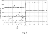
- Fig. 7 shows the suitability of the singular values of a matrix of measured values for the detection of a leak.
- the measurement shown initially shows the course of individual singular values 29 to 33 for the defect-free state. From a reading of 100, the measurement shows a condition in which the leak chamber was filled with the second oil. In the example shown, this results in a change of each singular value.
- the measurement shows the fundamental suitability of the singular values of the matrix as monitoring parameters and in particular for the detection of leakage.
Landscapes
- Physics & Mathematics (AREA)
- Electromagnetism (AREA)
- Fluid Mechanics (AREA)
- General Physics & Mathematics (AREA)
- Thermal Sciences (AREA)
- Examining Or Testing Airtightness (AREA)
- Radar Systems Or Details Thereof (AREA)
- Measurement Of Levels Of Liquids Or Fluent Solid Materials (AREA)
Applications Claiming Priority (1)
| Application Number | Priority Date | Filing Date | Title |
|---|---|---|---|
| DE102016108665.7A DE102016108665B4 (de) | 2016-05-11 | 2016-05-11 | Verfahren zur Überwachung eines nach dem Radarprinzip arbeitenden Füllstandmessgeräts und Füllstandmessgerät |
Publications (2)
| Publication Number | Publication Date |
|---|---|
| EP3244176A1 true EP3244176A1 (fr) | 2017-11-15 |
| EP3244176B1 EP3244176B1 (fr) | 2021-07-21 |
Family
ID=58488897
Family Applications (1)
| Application Number | Title | Priority Date | Filing Date |
|---|---|---|---|
| EP17164546.8A Active EP3244176B1 (fr) | 2016-05-11 | 2017-04-03 | Procédé de surveillance d'une jauge de niveau fonctionnant sur le principe du radar et jauge de niveau |
Country Status (4)
| Country | Link |
|---|---|
| US (1) | US10718655B2 (fr) |
| EP (1) | EP3244176B1 (fr) |
| CN (1) | CN107389152B (fr) |
| DE (1) | DE102016108665B4 (fr) |
Families Citing this family (2)
| Publication number | Priority date | Publication date | Assignee | Title |
|---|---|---|---|---|
| CN108955818A (zh) * | 2018-08-10 | 2018-12-07 | 合肥市恒昌自动化控制有限责任公司 | 带有泄漏检测功能的雷达物位计 |
| CN119714465A (zh) * | 2024-11-25 | 2025-03-28 | 北京航天计量测试技术研究所 | 一种具有泄露自诊断功能的料位计装置及监测方法 |
Citations (5)
| Publication number | Priority date | Publication date | Assignee | Title |
|---|---|---|---|---|
| US20060225499A1 (en) * | 2005-04-07 | 2006-10-12 | Rosemount Inc. | Tank seal for guided wave radar level measurement |
| DE102006019191A1 (de) | 2006-04-21 | 2007-10-25 | Endress + Hauser Gmbh + Co. Kg | Verfahren zur Ermittlung und Überwachung des Füllstands eines Mediums in einem Behälter |
| WO2010104461A1 (fr) * | 2009-03-10 | 2010-09-16 | Rosemount Tank Radar Ab | Système de jauge de niveau radar à détection de fuite |
| DE102012014267A1 (de) | 2012-07-19 | 2014-01-23 | Krohne S.A. | Verfahren zur Zustandsüberwachung eines nach dem Radar-Prinzip arbeitenden Füllstandmessgeräts und entsprechendes Füllstandmessgerät |
| US20140103950A1 (en) | 2012-10-17 | 2014-04-17 | Magnetrol International, Incorporated | Guided wave radar probe with leak detection |
Family Cites Families (11)
| Publication number | Priority date | Publication date | Assignee | Title |
|---|---|---|---|---|
| GB1054455A (fr) * | 1964-02-25 | |||
| US5996406A (en) * | 1997-05-20 | 1999-12-07 | Motorola, Inc. | Advanced signal process for a material storage measuring device |
| DE29822507U1 (de) * | 1998-12-17 | 1999-02-25 | Vega Grieshaber Kg, 77709 Wolfach | Füllstandmeßvorrichtung |
| US6775533B2 (en) | 2001-07-27 | 2004-08-10 | Nokia Corporation | Apparatus, and associated method, for transferring data between a first target entity and a second target entity of a mobile radio communication system |
| US20030222654A1 (en) * | 2001-11-30 | 2003-12-04 | Furse Cynthia M. | Cable testing, cable length, and liquid level determination system utilizing a standing wave reflectometer |
| US7576683B2 (en) * | 2006-08-07 | 2009-08-18 | Honeywell International Inc. | Methods and systems for reducing interference caused by antenna leakage signals |
| US8069721B2 (en) * | 2007-05-16 | 2011-12-06 | Rosemount Tank Radar Ab | Radar level gauge system having limited transmission power |
| DE102009060742A1 (de) * | 2009-12-30 | 2011-07-07 | NEGELE Messtechnik GmbH, 87743 | Einrichtung zum Erkennen eines Pegelstandes |
| DE102012101725A1 (de) * | 2012-03-01 | 2013-09-05 | Sick Ag | Verfahren zur Füllstandsmessung |
| DE102014112228A1 (de) * | 2014-08-26 | 2016-03-03 | Endress + Hauser Gmbh + Co. Kg | Verfahren zur Vermeidung von Phasensprüngen |
| EP3067711B1 (fr) * | 2015-03-13 | 2019-12-18 | Honeywell International Inc. | Appareil et procédé de réglage de largeur d'impulsion radar à ondes guidées pour optimiser des mesures |
-
2016
- 2016-05-11 DE DE102016108665.7A patent/DE102016108665B4/de not_active Expired - Fee Related
-
2017
- 2017-04-03 EP EP17164546.8A patent/EP3244176B1/fr active Active
- 2017-05-10 US US15/591,480 patent/US10718655B2/en active Active
- 2017-05-11 CN CN201710328917.8A patent/CN107389152B/zh active Active
Patent Citations (5)
| Publication number | Priority date | Publication date | Assignee | Title |
|---|---|---|---|---|
| US20060225499A1 (en) * | 2005-04-07 | 2006-10-12 | Rosemount Inc. | Tank seal for guided wave radar level measurement |
| DE102006019191A1 (de) | 2006-04-21 | 2007-10-25 | Endress + Hauser Gmbh + Co. Kg | Verfahren zur Ermittlung und Überwachung des Füllstands eines Mediums in einem Behälter |
| WO2010104461A1 (fr) * | 2009-03-10 | 2010-09-16 | Rosemount Tank Radar Ab | Système de jauge de niveau radar à détection de fuite |
| DE102012014267A1 (de) | 2012-07-19 | 2014-01-23 | Krohne S.A. | Verfahren zur Zustandsüberwachung eines nach dem Radar-Prinzip arbeitenden Füllstandmessgeräts und entsprechendes Füllstandmessgerät |
| US20140103950A1 (en) | 2012-10-17 | 2014-04-17 | Magnetrol International, Incorporated | Guided wave radar probe with leak detection |
Also Published As
| Publication number | Publication date |
|---|---|
| CN107389152A (zh) | 2017-11-24 |
| US10718655B2 (en) | 2020-07-21 |
| DE102016108665A1 (de) | 2017-11-16 |
| US20170328762A1 (en) | 2017-11-16 |
| EP3244176B1 (fr) | 2021-07-21 |
| CN107389152B (zh) | 2020-09-01 |
| DE102016108665B4 (de) | 2020-09-17 |
Similar Documents
| Publication | Publication Date | Title |
|---|---|---|
| EP2634541B1 (fr) | Procédé de mesure de niveau de remplissage | |
| DE102012003373B4 (de) | Verfahren zur Überwachung und Verfahren zum Betreiben eines nach dem Radar-Prinzip arbeitenden Füllstandmesssystems und entsprechendes Füllstandmesssystem | |
| EP1412710A1 (fr) | Procede pour evaluer les signaux de mesure d'un appareil de mesure fonctionnant selon le principe du temps de propagation | |
| EP2527802B1 (fr) | Dispositif et procédé de détermination de caractéristiques de milieux et de récipients | |
| EP2527804B1 (fr) | Procédé de reconnaissance d'échos multiples et d'échos de sol | |
| DE202016008526U1 (de) | Vorrichtung zum Messen des Durchmessers und/oder der Wanddicke eines Strangs | |
| EP2527801A1 (fr) | Dispositif et procédé de détermination de caractéristiques de milieux et de récipients | |
| DE10308495A1 (de) | Vorrichtung zur Bestimmung und/oder Überwachung des Füllstands eines Mediums in einem Behälter | |
| EP3025128B1 (fr) | Procédé pour déterminer et surveiller le niveau d'un fluide dans un récipient selon un procédé de mesure du temps de propagation | |
| EP2687830B1 (fr) | Procédé de surveillance de l'état d'un appareil de mesure du niveau de remplissage fonctionnant selon le principe du radar et appareil de mesure du niveau de remplissage correspondant | |
| DE112006002933T5 (de) | Radarfüllstandmesssystem und Übertragungsleitungssonde für die Verwendung in einem solchen System | |
| DE102016101756B4 (de) | Verfahren zur Bestimmung und Anzeige der optimalen Materialstärke bei der Füllstandmessung mit Radarsensoren | |
| EP2652465B1 (fr) | Détermination de propriétés de fluide lors de la mesure d'un niveau de remplissage | |
| EP3112821A1 (fr) | Procede et appareil de mesure de niveau de remplissage | |
| DE102005063079B4 (de) | Verfahren zur Ermittlung und Überwachung des Füllstands eines Mediums in einem Behälter | |
| EP3746753B1 (fr) | Procédé de détection d'états d'erreur potentiels sur un dispositif de mesure de remplissage à base de fmcw | |
| EP3244176B1 (fr) | Procédé de surveillance d'une jauge de niveau fonctionnant sur le principe du radar et jauge de niveau | |
| EP4356080A1 (fr) | Mesure d'un niveau de remplissage à l'aide d'un algorithme d'apprentissage automatique | |
| EP1456612A2 (fr) | Procede permettant de determiner et / ou de surveiller une grandeur de processus physique ou chimique | |
| DE102014101410A1 (de) | Vorrichtung zur Bestimmung oder Überwachung des Füllstands eines in einemBehälter gelagerten Füllguts | |
| EP1039273B1 (fr) | Procédé de mesure du niveau d' un fluide | |
| DE102005011778A1 (de) | Verfahren zur Messung des Füllstands eines in einem Behälter vorgesehenen Mediums auf der Grundlage des Radar-Prinzips | |
| DE102016213324B3 (de) | Füllstandsmessgerät nach dem Zeitbereichsreflektometrie-Prinzip sowie Verfahren zum Betreiben eines solchen Füllstandsmessgeräts | |
| DE29822507U1 (de) | Füllstandmeßvorrichtung | |
| DE102020124404A1 (de) | Integriertes Messgerät mit Füll- und/oder Grenzstandsensor und Druckmesszelle sowie Anordnung eines integrierten Messgerätes an einem Behälter |
Legal Events
| Date | Code | Title | Description |
|---|---|---|---|
| PUAI | Public reference made under article 153(3) epc to a published international application that has entered the european phase |
Free format text: ORIGINAL CODE: 0009012 |
|
| STAA | Information on the status of an ep patent application or granted ep patent |
Free format text: STATUS: THE APPLICATION HAS BEEN PUBLISHED |
|
| AK | Designated contracting states |
Kind code of ref document: A1 Designated state(s): AL AT BE BG CH CY CZ DE DK EE ES FI FR GB GR HR HU IE IS IT LI LT LU LV MC MK MT NL NO PL PT RO RS SE SI SK SM TR |
|
| AX | Request for extension of the european patent |
Extension state: BA ME |
|
| STAA | Information on the status of an ep patent application or granted ep patent |
Free format text: STATUS: REQUEST FOR EXAMINATION WAS MADE |
|
| 17P | Request for examination filed |
Effective date: 20180515 |
|
| RBV | Designated contracting states (corrected) |
Designated state(s): AL AT BE BG CH CY CZ DE DK EE ES FI FR GB GR HR HU IE IS IT LI LT LU LV MC MK MT NL NO PL PT RO RS SE SI SK SM TR |
|
| STAA | Information on the status of an ep patent application or granted ep patent |
Free format text: STATUS: EXAMINATION IS IN PROGRESS |
|
| 17Q | First examination report despatched |
Effective date: 20181001 |
|
| RIC1 | Information provided on ipc code assigned before grant |
Ipc: G01S 7/288 20060101ALI20201102BHEP Ipc: G01F 23/284 20060101AFI20201102BHEP |
|
| GRAP | Despatch of communication of intention to grant a patent |
Free format text: ORIGINAL CODE: EPIDOSNIGR1 |
|
| STAA | Information on the status of an ep patent application or granted ep patent |
Free format text: STATUS: GRANT OF PATENT IS INTENDED |
|
| GRAS | Grant fee paid |
Free format text: ORIGINAL CODE: EPIDOSNIGR3 |
|
| INTG | Intention to grant announced |
Effective date: 20210210 |
|
| RAP1 | Party data changed (applicant data changed or rights of an application transferred) |
Owner name: KROHNE S.A.S. |
|
| RIN1 | Information on inventor provided before grant (corrected) |
Inventor name: KESBA, MAHMOUD KHODJET Inventor name: PICHOT, VINCENT |
|
| GRAA | (expected) grant |
Free format text: ORIGINAL CODE: 0009210 |
|
| STAA | Information on the status of an ep patent application or granted ep patent |
Free format text: STATUS: THE PATENT HAS BEEN GRANTED |
|
| AK | Designated contracting states |
Kind code of ref document: B1 Designated state(s): AL AT BE BG CH CY CZ DE DK EE ES FI FR GB GR HR HU IE IS IT LI LT LU LV MC MK MT NL NO PL PT RO RS SE SI SK SM TR |
|
| REG | Reference to a national code |
Ref country code: GB Ref legal event code: FG4D Free format text: NOT ENGLISH |
|
| REG | Reference to a national code |
Ref country code: CH Ref legal event code: EP |
|
| REG | Reference to a national code |
Ref country code: DE Ref legal event code: R096 Ref document number: 502017010935 Country of ref document: DE |
|
| REG | Reference to a national code |
Ref country code: AT Ref legal event code: REF Ref document number: 1413002 Country of ref document: AT Kind code of ref document: T Effective date: 20210815 |
|
| REG | Reference to a national code |
Ref country code: IE Ref legal event code: FG4D Free format text: LANGUAGE OF EP DOCUMENT: GERMAN |
|
| REG | Reference to a national code |
Ref country code: LT Ref legal event code: MG9D |
|
| REG | Reference to a national code |
Ref country code: NL Ref legal event code: MP Effective date: 20210721 |
|
| PG25 | Lapsed in a contracting state [announced via postgrant information from national office to epo] |
Ref country code: HR Free format text: LAPSE BECAUSE OF FAILURE TO SUBMIT A TRANSLATION OF THE DESCRIPTION OR TO PAY THE FEE WITHIN THE PRESCRIBED TIME-LIMIT Effective date: 20210721 Ref country code: FI Free format text: LAPSE BECAUSE OF FAILURE TO SUBMIT A TRANSLATION OF THE DESCRIPTION OR TO PAY THE FEE WITHIN THE PRESCRIBED TIME-LIMIT Effective date: 20210721 Ref country code: ES Free format text: LAPSE BECAUSE OF FAILURE TO SUBMIT A TRANSLATION OF THE DESCRIPTION OR TO PAY THE FEE WITHIN THE PRESCRIBED TIME-LIMIT Effective date: 20210721 Ref country code: NO Free format text: LAPSE BECAUSE OF FAILURE TO SUBMIT A TRANSLATION OF THE DESCRIPTION OR TO PAY THE FEE WITHIN THE PRESCRIBED TIME-LIMIT Effective date: 20211021 Ref country code: NL Free format text: LAPSE BECAUSE OF FAILURE TO SUBMIT A TRANSLATION OF THE DESCRIPTION OR TO PAY THE FEE WITHIN THE PRESCRIBED TIME-LIMIT Effective date: 20210721 Ref country code: PT Free format text: LAPSE BECAUSE OF FAILURE TO SUBMIT A TRANSLATION OF THE DESCRIPTION OR TO PAY THE FEE WITHIN THE PRESCRIBED TIME-LIMIT Effective date: 20211122 Ref country code: BG Free format text: LAPSE BECAUSE OF FAILURE TO SUBMIT A TRANSLATION OF THE DESCRIPTION OR TO PAY THE FEE WITHIN THE PRESCRIBED TIME-LIMIT Effective date: 20211021 Ref country code: LT Free format text: LAPSE BECAUSE OF FAILURE TO SUBMIT A TRANSLATION OF THE DESCRIPTION OR TO PAY THE FEE WITHIN THE PRESCRIBED TIME-LIMIT Effective date: 20210721 Ref country code: SE Free format text: LAPSE BECAUSE OF FAILURE TO SUBMIT A TRANSLATION OF THE DESCRIPTION OR TO PAY THE FEE WITHIN THE PRESCRIBED TIME-LIMIT Effective date: 20210721 Ref country code: RS Free format text: LAPSE BECAUSE OF FAILURE TO SUBMIT A TRANSLATION OF THE DESCRIPTION OR TO PAY THE FEE WITHIN THE PRESCRIBED TIME-LIMIT Effective date: 20210721 |
|
| PG25 | Lapsed in a contracting state [announced via postgrant information from national office to epo] |
Ref country code: PL Free format text: LAPSE BECAUSE OF FAILURE TO SUBMIT A TRANSLATION OF THE DESCRIPTION OR TO PAY THE FEE WITHIN THE PRESCRIBED TIME-LIMIT Effective date: 20210721 Ref country code: LV Free format text: LAPSE BECAUSE OF FAILURE TO SUBMIT A TRANSLATION OF THE DESCRIPTION OR TO PAY THE FEE WITHIN THE PRESCRIBED TIME-LIMIT Effective date: 20210721 Ref country code: GR Free format text: LAPSE BECAUSE OF FAILURE TO SUBMIT A TRANSLATION OF THE DESCRIPTION OR TO PAY THE FEE WITHIN THE PRESCRIBED TIME-LIMIT Effective date: 20211022 |
|
| REG | Reference to a national code |
Ref country code: DE Ref legal event code: R097 Ref document number: 502017010935 Country of ref document: DE |
|
| PG25 | Lapsed in a contracting state [announced via postgrant information from national office to epo] |
Ref country code: DK Free format text: LAPSE BECAUSE OF FAILURE TO SUBMIT A TRANSLATION OF THE DESCRIPTION OR TO PAY THE FEE WITHIN THE PRESCRIBED TIME-LIMIT Effective date: 20210721 |
|
| PLBE | No opposition filed within time limit |
Free format text: ORIGINAL CODE: 0009261 |
|
| STAA | Information on the status of an ep patent application or granted ep patent |
Free format text: STATUS: NO OPPOSITION FILED WITHIN TIME LIMIT |
|
| PG25 | Lapsed in a contracting state [announced via postgrant information from national office to epo] |
Ref country code: SM Free format text: LAPSE BECAUSE OF FAILURE TO SUBMIT A TRANSLATION OF THE DESCRIPTION OR TO PAY THE FEE WITHIN THE PRESCRIBED TIME-LIMIT Effective date: 20210721 Ref country code: SK Free format text: LAPSE BECAUSE OF FAILURE TO SUBMIT A TRANSLATION OF THE DESCRIPTION OR TO PAY THE FEE WITHIN THE PRESCRIBED TIME-LIMIT Effective date: 20210721 Ref country code: RO Free format text: LAPSE BECAUSE OF FAILURE TO SUBMIT A TRANSLATION OF THE DESCRIPTION OR TO PAY THE FEE WITHIN THE PRESCRIBED TIME-LIMIT Effective date: 20210721 Ref country code: EE Free format text: LAPSE BECAUSE OF FAILURE TO SUBMIT A TRANSLATION OF THE DESCRIPTION OR TO PAY THE FEE WITHIN THE PRESCRIBED TIME-LIMIT Effective date: 20210721 Ref country code: CZ Free format text: LAPSE BECAUSE OF FAILURE TO SUBMIT A TRANSLATION OF THE DESCRIPTION OR TO PAY THE FEE WITHIN THE PRESCRIBED TIME-LIMIT Effective date: 20210721 Ref country code: AL Free format text: LAPSE BECAUSE OF FAILURE TO SUBMIT A TRANSLATION OF THE DESCRIPTION OR TO PAY THE FEE WITHIN THE PRESCRIBED TIME-LIMIT Effective date: 20210721 |
|
| 26N | No opposition filed |
Effective date: 20220422 |
|
| PG25 | Lapsed in a contracting state [announced via postgrant information from national office to epo] |
Ref country code: IT Free format text: LAPSE BECAUSE OF FAILURE TO SUBMIT A TRANSLATION OF THE DESCRIPTION OR TO PAY THE FEE WITHIN THE PRESCRIBED TIME-LIMIT Effective date: 20210721 |
|
| PGFP | Annual fee paid to national office [announced via postgrant information from national office to epo] |
Ref country code: GB Payment date: 20220531 Year of fee payment: 6 |
|
| REG | Reference to a national code |
Ref country code: BE Ref legal event code: MM Effective date: 20220430 |
|
| PG25 | Lapsed in a contracting state [announced via postgrant information from national office to epo] |
Ref country code: MC Free format text: LAPSE BECAUSE OF FAILURE TO SUBMIT A TRANSLATION OF THE DESCRIPTION OR TO PAY THE FEE WITHIN THE PRESCRIBED TIME-LIMIT Effective date: 20210721 Ref country code: LU Free format text: LAPSE BECAUSE OF NON-PAYMENT OF DUE FEES Effective date: 20220403 |
|
| PG25 | Lapsed in a contracting state [announced via postgrant information from national office to epo] |
Ref country code: BE Free format text: LAPSE BECAUSE OF NON-PAYMENT OF DUE FEES Effective date: 20220430 |
|
| REG | Reference to a national code |
Ref country code: AT Ref legal event code: MM01 Ref document number: 1413002 Country of ref document: AT Kind code of ref document: T Effective date: 20220403 |
|
| P01 | Opt-out of the competence of the unified patent court (upc) registered |
Effective date: 20230607 |
|
| PG25 | Lapsed in a contracting state [announced via postgrant information from national office to epo] |
Ref country code: AT Free format text: LAPSE BECAUSE OF NON-PAYMENT OF DUE FEES Effective date: 20220403 |
|
| GBPC | Gb: european patent ceased through non-payment of renewal fee |
Effective date: 20230403 |
|
| PG25 | Lapsed in a contracting state [announced via postgrant information from national office to epo] |
Ref country code: GB Free format text: LAPSE BECAUSE OF NON-PAYMENT OF DUE FEES Effective date: 20230403 |
|
| PG25 | Lapsed in a contracting state [announced via postgrant information from national office to epo] |
Ref country code: GB Free format text: LAPSE BECAUSE OF NON-PAYMENT OF DUE FEES Effective date: 20230403 |
|
| PG25 | Lapsed in a contracting state [announced via postgrant information from national office to epo] |
Ref country code: HU Free format text: LAPSE BECAUSE OF FAILURE TO SUBMIT A TRANSLATION OF THE DESCRIPTION OR TO PAY THE FEE WITHIN THE PRESCRIBED TIME-LIMIT; INVALID AB INITIO Effective date: 20170403 |
|
| PG25 | Lapsed in a contracting state [announced via postgrant information from national office to epo] |
Ref country code: MK Free format text: LAPSE BECAUSE OF FAILURE TO SUBMIT A TRANSLATION OF THE DESCRIPTION OR TO PAY THE FEE WITHIN THE PRESCRIBED TIME-LIMIT Effective date: 20210721 Ref country code: CY Free format text: LAPSE BECAUSE OF FAILURE TO SUBMIT A TRANSLATION OF THE DESCRIPTION OR TO PAY THE FEE WITHIN THE PRESCRIBED TIME-LIMIT Effective date: 20210721 |
|
| PGFP | Annual fee paid to national office [announced via postgrant information from national office to epo] |
Ref country code: IE Payment date: 20240627 Year of fee payment: 8 |
|
| PG25 | Lapsed in a contracting state [announced via postgrant information from national office to epo] |
Ref country code: MT Free format text: LAPSE BECAUSE OF FAILURE TO SUBMIT A TRANSLATION OF THE DESCRIPTION OR TO PAY THE FEE WITHIN THE PRESCRIBED TIME-LIMIT Effective date: 20210721 |
|
| PGFP | Annual fee paid to national office [announced via postgrant information from national office to epo] |
Ref country code: DE Payment date: 20250617 Year of fee payment: 9 |
|
| PGFP | Annual fee paid to national office [announced via postgrant information from national office to epo] |
Ref country code: FR Payment date: 20250425 Year of fee payment: 9 |
|
| PGFP | Annual fee paid to national office [announced via postgrant information from national office to epo] |
Ref country code: CH Payment date: 20250501 Year of fee payment: 9 |
|
| PG25 | Lapsed in a contracting state [announced via postgrant information from national office to epo] |
Ref country code: TR Free format text: LAPSE BECAUSE OF FAILURE TO SUBMIT A TRANSLATION OF THE DESCRIPTION OR TO PAY THE FEE WITHIN THE PRESCRIBED TIME-LIMIT Effective date: 20210721 |
|
| PG25 | Lapsed in a contracting state [announced via postgrant information from national office to epo] |
Ref country code: IE Free format text: LAPSE BECAUSE OF NON-PAYMENT OF DUE FEES Effective date: 20250403 |