EP3245005B1 - Rotor et méthode pour actionner une centrifuge double - Google Patents
Rotor et méthode pour actionner une centrifuge double Download PDFInfo
- Publication number
- EP3245005B1 EP3245005B1 EP15808121.6A EP15808121A EP3245005B1 EP 3245005 B1 EP3245005 B1 EP 3245005B1 EP 15808121 A EP15808121 A EP 15808121A EP 3245005 B1 EP3245005 B1 EP 3245005B1
- Authority
- EP
- European Patent Office
- Prior art keywords
- rotary
- rotor
- sample container
- rotary head
- gearwheel
- Prior art date
- Legal status (The legal status is an assumption and is not a legal conclusion. Google has not performed a legal analysis and makes no representation as to the accuracy of the status listed.)
- Active
Links
Images

Classifications
-
- B—PERFORMING OPERATIONS; TRANSPORTING
- B04—CENTRIFUGAL APPARATUS OR MACHINES FOR CARRYING-OUT PHYSICAL OR CHEMICAL PROCESSES
- B04B—CENTRIFUGES
- B04B5/00—Other centrifuges
- B04B5/02—Centrifuges consisting of a plurality of separate bowls rotating round an axis situated between the bowls
-
- B—PERFORMING OPERATIONS; TRANSPORTING
- B01—PHYSICAL OR CHEMICAL PROCESSES OR APPARATUS IN GENERAL
- B01F—MIXING, e.g. DISSOLVING, EMULSIFYING OR DISPERSING
- B01F29/00—Mixers with rotating receptacles
- B01F29/10—Mixers with rotating receptacles with receptacles rotated about two different axes, e.g. receptacles having planetary motion
-
- B—PERFORMING OPERATIONS; TRANSPORTING
- B01—PHYSICAL OR CHEMICAL PROCESSES OR APPARATUS IN GENERAL
- B01F—MIXING, e.g. DISSOLVING, EMULSIFYING OR DISPERSING
- B01F29/00—Mixers with rotating receptacles
- B01F29/15—Use of centrifuges for mixing
-
- B—PERFORMING OPERATIONS; TRANSPORTING
- B01—PHYSICAL OR CHEMICAL PROCESSES OR APPARATUS IN GENERAL
- B01F—MIXING, e.g. DISSOLVING, EMULSIFYING OR DISPERSING
- B01F35/00—Accessories for mixers; Auxiliary operations or auxiliary devices; Parts or details of general application
- B01F35/50—Mixing receptacles
-
- B—PERFORMING OPERATIONS; TRANSPORTING
- B02—CRUSHING, PULVERISING, OR DISINTEGRATING; PREPARATORY TREATMENT OF GRAIN FOR MILLING
- B02C—CRUSHING, PULVERISING, OR DISINTEGRATING IN GENERAL; MILLING GRAIN
- B02C17/00—Disintegrating by tumbling mills, i.e. mills having a container charged with the material to be disintegrated with or without special disintegrating members such as pebbles or balls
- B02C17/04—Disintegrating by tumbling mills, i.e. mills having a container charged with the material to be disintegrated with or without special disintegrating members such as pebbles or balls with unperforated container
- B02C17/08—Disintegrating by tumbling mills, i.e. mills having a container charged with the material to be disintegrated with or without special disintegrating members such as pebbles or balls with unperforated container with containers performing a planetary movement
-
- B—PERFORMING OPERATIONS; TRANSPORTING
- B04—CENTRIFUGAL APPARATUS OR MACHINES FOR CARRYING-OUT PHYSICAL OR CHEMICAL PROCESSES
- B04B—CENTRIFUGES
- B04B9/00—Drives specially designed for centrifuges; Arrangement or disposition of transmission gearing; Suspending or balancing rotary bowls
- B04B9/12—Suspending rotary bowls ; Bearings; Packings for bearings
-
- B—PERFORMING OPERATIONS; TRANSPORTING
- B04—CENTRIFUGAL APPARATUS OR MACHINES FOR CARRYING-OUT PHYSICAL OR CHEMICAL PROCESSES
- B04B—CENTRIFUGES
- B04B9/00—Drives specially designed for centrifuges; Arrangement or disposition of transmission gearing; Suspending or balancing rotary bowls
- B04B9/14—Balancing rotary bowls ; Schrappers
-
- B—PERFORMING OPERATIONS; TRANSPORTING
- B01—PHYSICAL OR CHEMICAL PROCESSES OR APPARATUS IN GENERAL
- B01F—MIXING, e.g. DISSOLVING, EMULSIFYING OR DISPERSING
- B01F35/00—Accessories for mixers; Auxiliary operations or auxiliary devices; Parts or details of general application
- B01F35/30—Driving arrangements; Transmissions; Couplings; Brakes
- B01F2035/35—Use of other general mechanical engineering elements in mixing devices
- B01F2035/352—Bearings
-
- B—PERFORMING OPERATIONS; TRANSPORTING
- B01—PHYSICAL OR CHEMICAL PROCESSES OR APPARATUS IN GENERAL
- B01F—MIXING, e.g. DISSOLVING, EMULSIFYING OR DISPERSING
- B01F29/00—Mixers with rotating receptacles
- B01F29/40—Parts or components, e.g. receptacles, feeding or discharging means
- B01F29/403—Disposition of the rotor axis
- B01F29/4035—Disposition of the rotor axis with a receptacle rotating around two or more axes
-
- B—PERFORMING OPERATIONS; TRANSPORTING
- B01—PHYSICAL OR CHEMICAL PROCESSES OR APPARATUS IN GENERAL
- B01F—MIXING, e.g. DISSOLVING, EMULSIFYING OR DISPERSING
- B01F35/00—Accessories for mixers; Auxiliary operations or auxiliary devices; Parts or details of general application
- B01F35/30—Driving arrangements; Transmissions; Couplings; Brakes
- B01F35/33—Transmissions; Means for modifying the speed or direction of rotation
- B01F35/333—Transmissions; Means for modifying the speed or direction of rotation the rotation sense being changeable, e.g. to mix or aerate, to move a fluid forward or backward or to suck or blow
Definitions
- the invention relates to a rotor of a dual centrifuge according to the type specified in the preamble of claim 1, and relates to a method according to claim 14.
- the homogenization of materials, as well as the mixing or grinding of samples in sample containers, the longitudinal axis of which is preferably arranged at an angle of 70-110° to the rotation axis of a rotary unit, is based on the rapid movement of the materials in the sample containers, depending on the position of the containers in relation to the centrifugal force of the dual centrifuge. These rapid movements of material in the containers temporarily lead to an uneven loading of the dual centrifuge and thus to imbalance.
- the high number of revolutions required for many homogenization, mixing or grinding processes then lead to correspondingly large mass imbalances.
- the alignment of the sample containers can be a major cause of the formation of imbalances in the rotor. If the sample container has a longitudinal axis that is not concentric or parallel to the axis of rotation of the rotary unit, there is a higher risk of imbalances occurring in the rotor. On the other hand, an asynchronous arrangement of the sample containers in the individual rotary units increases the effect of the mass imbalances, since the mass movements in the sample containers cannot be synchronous.
- the object of the invention is to create a rotor of a dual centrifuge while avoiding the disadvantages mentioned, in which the mass shifts necessary for the process and thus imbalances in the sample containers occur, but in which the imbalances of the complete rotor unit do not exceed the technically acceptable level.
- the invention is based on the finding of increasing the total mass of the rotor by means of additional damping masses and/or aligning the sample container holder and thus the sample containers in the same way to the rotor and synchronizing the movement of the at least two existing rotary units as optimally as possible.
- a rotor of a dual centrifuge that can rotate about a main axis in the centrifuge
- the rotating heads can be driven about the rotation axis relative to the rotor by a further rotating mechanism of the centrifuge and have a rotating head holder for at least one sample container and/or at least one sample container holder.
- the rotation axis of the rotating unit of the rotor is aligned at an angle to the drive axis of the rotor.
- the rotating head holder is designed to hold an elongated sample container holder and/or an elongated sample container.
- the longitudinal axis of the sample container holder inserted into the rotating head holder or the longitudinal axis of the sample container inserted into the rotating head holder is aligned perpendicular to the rotation axis of the rotating head or between greater than 0° and less than 90° to the rotation axis.
- two rotary units are provided which are of the same design and aligned in the same way to the main axis in a zero position.
- the rotary head holders, preferably with the sample container holders and/or the sample containers, are each arranged in the same way in the rotary units and the rotary units move synchronously with one another during operation.
- the drive axis - main axis - of the centrifuge is the mirror axis of the rotary units.
- the identical arrangement of the rotary head holders, in particular with the sample container holders and/or the sample containers, and the synchronous movements of the rotary units counteract the occurrence of imbalances in the entire centrifuge. It is advantageous if at least one connection area is also provided on the rotor, to which at least one damping mass can be optionally detachably attached and firmly attached for operation via a fixation.
- the further rotary mechanism is designed in such a way that a first gearwheel that is stationary relative to the motor shaft and a second gearwheel that is connected to the rotary head are provided, whereby the motor shaft drives the rotor and, due to the rotary movement of the rotor relative to the stationary first gearwheel, drives the second gearwheel that is operatively connected to the first gearwheel, thereby moving the rotary head.
- This design of the rotary mechanism ensures a particularly uniform drive of the individual rotary heads and thus a uniform rotation of the individual sample containers.
- a first bore is provided in each rotary head in the zero position, which passes through the second gearwheel and, in the zero position, is aligned with a corresponding second bore in a part that is stationary relative to the rotor.
- a pin in the zero position of the rotary unit is inserted into the first and second bore can be introduced, whereby the rotary unit is secured in the zero position against rotation from the zero position.
- the rotary heads are aligned even more precisely than is possible by mere visual inspection.
- no unwanted rotation is possible when inserting the rotor into the centrifuge. This increases safety during use.
- the features of the first aspect of the invention are also implemented in this context.
- the imbalance can be counteracted even more specifically. In other words, an optimum can be created between the highest possible damping mass to compensate for the imbalance and the total mass of the rotor, which, however, should not be too high due to the necessary rotor acceleration and the existing motor suspension.
- the centrifuge's safety pot can be designed to be weaker.
- a set of mass elements of different weights is therefore provided, from which a predetermined weight damping mass is formed as required, or several predetermined weights, each of the same and/or different, damping masses are formed.
- This enables a particularly precise selection of the damping mass in order to meet a wide variety of requirements, such as the uneven loading of the centrifuge with samples or the different sizes of the mass moved by the rotary head holder with sample container holder and/or sample container.
- damping mass instead of assembling the damping mass from different mass elements as required, to provide a set of damping masses of different weights and/or the same weight from the outset. If required, one damping mass is introduced into the connection area or several damping masses are introduced into connection areas. This allows the centrifuge operator to quickly select and attach the necessary damping mass for the respective application.
- At least one sample container holder or one sample container can be attached to the rotary head holder, and the damping masses are determined depending on a total mass of a sample container with sample load and sample container holder inserted into the sample container holder or depending on a total mass of a sample container with sample load and the mass of the rotary unit. This ensures exact compensation of the masses that can cause an imbalance. The operation of the centrifuge becomes even quieter and safer.
- the sum of the damping mass or masses attached to the rotor is or are designed in a ratio of at least 0.5:1, in particular 1:1, to the total mass, which is made up of the mass of the sample loads, the sample containers, the sample container holders, the rotary head holder and the rotary unit.
- the rotary heads and thus the rotary head holders with the sample holders and/or the sample containers have a zero position relative to the rotor, in which intersection points of the radial line perpendicular to the axis of rotation of the rotary units through the zero position with a radial line perpendicular to the main axis of the rotor are formed.
- the sample holders and the sample containers can only be inserted into the rotary head holder in one orientation. All intersection points lie on a circle around the main axis. This arrangement makes it easy to synchronize the rotary heads, since in addition to the actual rotary movement, the starting points of the rotary movement are also determined in relation to one another.
- the rotary head holders and the sample containers with samples placed directly or indirectly in them are preferably all aligned in the same way in relation to the rotor in the zero positions of the rotary heads.
- one cover of the sample container is arranged radially outward in relation to the rotor. This further improves the synchronization of the rotary heads.
- the sum of the teeth of the engaging second gears of the rotary heads is an integer divisible by the number of teeth of the first gear, it is easier to maintain constant uniform angles between the rotary heads on the one hand and the rotor on the other.
- the pins assigned to the holes can be connected to one another via a clamp so that the position of the pins ensures that the weight distribution of two rotary units is symmetrical to one another. This means that the alignment of all rotary heads can be secured with a single movement.
- the pin and/or the clamp are provided with a blocking device which, when the pin or clamp is mounted, prevents it from closing.
- a centrifuge lid This can be done, for example, by using particularly long pins or a particularly protruding clamp. This prevents the centrifuge from being started while the rotary heads are still secured in their respective zero positions, which could cause damage to the device.
- the arrangement of hole and pin can be reversed so that the rotary head has a pin and the clamp has an associated hole.
- the accuracy of the alignment of the rotary heads is significantly improved by the fact that the zero position has a maximum play of 2.5° in the direction of rotation.
- the rotary heads are coupled to one another via a further rotary mechanism and the angular position of the rotary heads relative to one another is determined by different rotary units. This significantly reduces the risk of the synchronization of the movement of the rotary heads being lost during operation of the centrifuge.
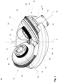
- Fig. 1 shows a perspective view of a rotor 10 according to the invention as part of a symmetrical centrifuge with two rotary units 26 for use in a dual centrifuge not shown in the figures.
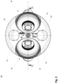
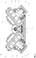
- Fig. 2 shows a top view and Fig. 3 a side sectional view of the Fig. 1 illustrated rotor 10.
- the rotor 10 has a rotor head 12 with a rotationally symmetrical basic shape which describes an envelope.
- the rotor head 12 is provided with a base 14 and a wall 18 which runs around the base 14 and extends upwards.
- a drive axis A runs vertically into the center 16 of the rotor head 12.
- a drive shaft (not shown in the figures) passes through the rotor head 12 with its free end through a recess 20 provided in the base 14 which is concentric with the drive axis A.
- a receiving tube 22 which is made in one piece with the base 14 and which serves to center and vertically fix the rotor head 12 on the drive shaft.
- the wall 18 has a vertical section 18a and a section 18b inclined downwards in the direction of the drive axis.
- Two recesses 24 are provided which are opposite one another with respect to the drive axis A and which partially pass through the vertical section 18a of the wall 18 and the inclined section 18b of the wall 18.
- the rotary units 26 are each inserted into the recesses 24.
- the rotary units 26 each have a rotation axis R1, R2 and are aligned by the recesses 24 such that the rotation axes R1 and R2 intersect the drive axis A above the rotor 10 at an acute angle. Furthermore, the free ends of the rotary units 26 pointing away from the drive axis A, namely the housings 28 explained below, see Fig. 4 , in the region of the inclined section 18b of the wall 18 beyond the envelope.
- the rotary unit 26 has a largely rotationally symmetrical outer contour and comprises a rotatably mounted rotary head 30, see Fig. 3 , for supporting a rotary head holder 80 with an inserted sample container holder 100, 110 for sample containers with samples to be centrifuged and a housing 28 into which a bearing 32 for the rotary head 30 is inserted, into which in turn the rotary head 30 engages with a bearing shaft provided on its side facing the housing 28, not shown for the sake of clarity.
- the rotary head 30 has an outer wall 34 arranged concentrically to the rotation axis R1, R2.
- the housing 28 is provided with a wall 38 arranged concentrically to the rotation axis R1, R2.
- the diameter of the rotary head 30 is larger than that of the housing 28, so that a shoulder 36 is formed between the outer wall 34 of the rotary head 30 and the wall 38 of the housing 28, with which the rotary unit 26 partially engages in the recess 24 assigned to it, see Fig. 1 .
- the dimensions of the housing 28 are adapted to the respective associated areas of the recesses 24.
- a groove is provided in the housing 28 that is parallel to the axis of rotation R1, R2, and a projection is provided on the rotor head 12 that is associated with the groove.
- the groove and projection are not shown in the figures for reasons of clarity.
- the arrangement of the groove and projection can also be interchanged. It is also conceivable to choose a polygonal design instead of the cylindrical design of the housing 28 in order to achieve a rotationally fixed installation of a housing in a rotor head.
- a closure cover 40 On the side remote from the housing 28, the rotary head 30 is further closed by a closure cover 40 arranged concentrically with the rotation axis R1, R2.
- a locking button 42 is also provided concentrically on the closure cover 40, which serves as a handle to unlock and remove the closure cover 40 by a rotary movement or to put the closure cover 40 on and lock it by a rotary movement opposite to the unlocking direction.
- a projection 44 is provided all around, see e.g. Fig. 4 , which defines a toothing in the form of a gear 46 concentric with the rotation axis R1, R2, which is connected in a rotationally fixed manner to the outer wall 34.
- a central gear below the rotor head 12 (not shown in the figures for the sake of clarity), which is connected in a rotationally fixed manner to the rotating rotor head 12, for example by a screw connection to a motor housing (not shown in the figures).
- a transmission gear can be provided between the gear 46 and the central gear in order to achieve different transmission ratios.
- the ratio of main rotation (rotation of the rotor 10) to reverse rotation (rotation of the rotary head 30) is given by the transmission ratio between the gear 46 and the central gear (not shown) and, if necessary, another transmission gear.
- the transmission gear (not shown) and the central gear are easily interchangeable. The speed ratio can therefore be changed in a simple manner by adjusting the diameter of the gear (not shown) and the central gear.
- Cooling fins 50 are provided on the side of the housing 28 remote from the rotating head 30.
- the cooling fins 42 are aligned perpendicular to the direction of rotation of the rotor head 12.
- the side of the wall 18 facing the center 16 of the rotor head 12 is designed as a connecting region 52 on which two disk-shaped damping masses 54 are arranged, which are opposite one another with respect to the center 16 of the rotor head 12.
- the damping masses 54 are provided in order to reduce the effects of imbalances which can occur in particular in the rotary units 26 during operation.
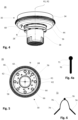
- Fig. 4 is the one in the Figures 1 to 3 shown rotary unit 26 with the cover 40 removed in a perspective view from below. This view shows the arrangement in particular of the projection 44 and the gear 46 on the outer wall of the rotary head 30 as well as the cooling fins 50 on the side of the housing 28 facing away from the rotary head 30.
- FIG. 5 is the one in Fig. 4
- the rotary unit 26 shown in FIG. 1 is shown from above.
- a base 60 which has a circular surface and a center point 62, and an inner wall 58 arranged on the circumference of the base 60 and running concentrically with the outer wall 34 of the rotary head 30, delimit an upwardly open receiving area 56 for a subsequently Fig. 7 shown rotary head holder 80.
- ten evenly spaced holes are provided in the base 60 on a circular line K2 running around the center point 62, by means of which the rotary head 30 and the housing 28 are riveted together and form a structural unit.
- a further circular line K2 which also runs around the center point 62, eight equally spaced recesses 66 are provided.
- the recesses 66 serve when using the rotary head holder 80, as shown for example in Fig. 7 shown, the accommodation of wedges, pins or the like, which are arranged on the rotary head holder 80 for guidance and to improve the safety of the bearing.
- a lateral guide (not shown here), which has a corresponding counter-guide on the outer wall, the rotary head holder 80 can only be introduced into the rotary unit in one orientation.
- a hole 68 is provided in the bottom 60 adjacent to the inner wall 58.
- the hole 68 passes through, as is also apparent from Fig. 4
- the bottom 60 completely and serves to accommodate a Fig. 4a shown pin 70.
- the bore 68 marks a zero position N of the rotary unit 26, by means of which the rotary unit 26 can be aligned so that it executes a synchronous movement with other rotary units 26 arranged in the rotor head 12.
- a further bore can be provided in order to maintain symmetry and thus avoid imbalance caused by the bore 68.
- the pin 70 has a spherical handle 71 at one end and is dimensioned in such a way that it passes through the bore 68 and with its free end into a hole in the rotor head 12 provided hole, which is not shown for the sake of clarity. This fixes the rotary unit 26 in the zero position N.
- the pin can be dimensioned in such a way that the lid of the centrifuge is prevented from closing.
- Fig. 6 shows a clamp 72 by means of which two rotary units 26 can be fixed simultaneously in their respective zero position N.
- a pin 74 is arranged at each of the two free ends of the clamp 72.
- the two pins 74 have the same length as the pin 70 and are spaced apart from one another via a spring-elastic connecting clamp 76 and are set at such an angle to one another that they can be inserted simultaneously into two holes 68 of two rotary heads 30.
- the spring-elastic design of the connecting clamp 76 enables small corrections to the distance and the angle of attack that are required during the insertion and removal of the pins 74.
- a spherical handle 78 is arranged centrally on the connecting clip 76.
- the handle 78 makes it easier to operate the clamp 72 and is positioned in such a way when the clamp 72 is inserted that it prevents a centrifuge lid from closing completely.
- Fig. 7 shows an embodiment of a rotary head holder 80, which is used for the safe storage of Figures 8a and 8b sample container holders 100 and 110 shown as examples can be introduced into the receiving area 56 of the rotary head 30.
- the outer circumference of the rotary head holder 80 is adapted to the receiving area 56.
- the rotary head holder 80 has a safety wall 82 and a base 84.
- An upwardly open cross-shaped receiving space 88 is delimited by an inner contour 86 of the safety wall 82 and the base 84.
- Two rectangular legs 88a and 88b of the receiving space 88 are arranged perpendicular to each other, the base areas of the first leg 86a and the second leg 86b being identical and corresponding to the base areas of the Figures 8a and 8b illustrated sample container holder 100, 110.
- the first leg 88a serves to accommodate the sample container holder 100.
- a recess 90 is provided in the safety wall 82 at both ends of the leg 88a, the two recesses 90 being arranged diametrically to one another with respect to the leg 88a.
- the recesses 90 serve to securely wedge the sample container holder 100 with inserted Centrifuge tubes into the rotary head holder 80 as shown in Fig. 8a will be explained in more detail.
- the second leg 88b serves to accommodate the sample container holder 110.
- a recess 92 is provided at one end of the leg 88b and two recesses 94 are provided in the safety wall 82 at the second end of the leg 88b.
- the recesses 92, 94 serve to securely wedge the sample container holder 110 in the rotary head holder 80, as can be seen from Fig. 8b will be explained in more detail.
- Fig. 8a shows a first sample container holder 100 according to the invention, which, as in connection with Fig. 7 described, is designed to be received in the first leg 88a of the rotary head holder 80.
- the sample container holder 100 has a recess 104 on each of the two end faces 102, into which a centrifuge tube (not shown for the sake of clarity) can be inserted as a sample container for vertical storage.
- a second sample container holder 110 is shown, which is designed to be received in the second leg 88b of the rotary head holder 80.
- the sample container holder 110 has a Figure 8b one recess 114 on the front side 112 facing the viewer and two recesses 114 on a front side 112 facing away from the viewer.
- centrifuge tubes (not shown) can be inserted into the recesses 114 for vertical storage.
- the end of a centrifuge tube protruding from the respective recess 114 also engages in an associated recess 92, 94 in the safety wall 82 on both end faces 112. As a result, the sample container holder 110 is wedged in the rotary head holder 80.
- the rotary head holder 80 and the sample container holders 100 and 110 were chosen as an example because an arrangement of elongated sample container holders with sample containers perpendicular to the Rotation axis R1, R2 of the rotary unit 26 carries a high risk of imbalances occurring, and therefore the attachment of damping mass is particularly advantageous.
- countless other examples of different storage of sample container holders for sample containers are conceivable, including the storage of the sample containers directly in the rotary head holder.
Landscapes
- Engineering & Computer Science (AREA)
- Food Science & Technology (AREA)
- Chemical & Material Sciences (AREA)
- Chemical Kinetics & Catalysis (AREA)
- Centrifugal Separators (AREA)
Claims (15)
- Rotor d'une centrifugeuse double, qui peut être amené en rotation autour d'un axe d'entraînement (A) dans une centrifugeuse, avec au moins deux unités rotatives (26) disposées de manière symétrique l'une par rapport à l'autre, qui présente respectivement un palier (32) et une tête rotative (30) reliée au palier (32), montée en rotation dans celui-ci par l'intermédiaire d'un axe de rotation (R1, R2), dans lequel la tête rotative (30) peut être entraînée par rapport au rotor d'un autre mécanisme de rotation de la centrifugeuse autour de l'axe de rotation (R1, R2) et présente un logement de tête rotative (80) pour au moins un récipient pour échantillon ou au moins un logement de récipient pour échantillon (100, 110), l'axe de rotation (R1, R2) de la tête rotative (30) est orienté de manière inclinée par rapport à l'axe d'entraînement (A) du rotor, le logement de tête rotative (80) est réalisé pour la réception d'un logement de récipient pour échantillon (100, 110) allongé ou d'un récipient pour échantillon allongé, l'axe longitudinal du logement de récipient pour échantillon (100, 110) introduit dans le logement de tête rotative (80) ou l'axe longitudinal du récipient pour échantillon introduit dans le logement de tête rotative (80) est orienté perpendiculairement à l'axe de rotation (R1, R2) de la tête rotative (30) ou entre plus de 0° à moins de 90° par rapport à l'axe de rotation (R1, R2), dans lequel deux des unités rotatives (26) sont prévues, qui sont réalisées de la même façon, dans lequel les unités rotatives (26) sont orientées de la même façon par rapport à l'axe d'entraînement (A) dans une position zéro (N), les logements de tête rotative (80) sont disposés et orientés dans l'unité rotative (26) respectivement de la même façon et les unités rotatives (26) pendant le fonctionnement exécutent avec les logements de tête rotative (80), les logements de récipient pour échantillon (100, 110) et/ou les récipients pour échantillon les uns avec les autres un mouvement synchrone, et dans lequel l'autre mécanisme de rotation est réalisé de telle sorte qu'une première roue dentée fixe par rapport à un arbre de moteur et une deuxième roue dentée (46) reliée à la tête rotative (30) est prévue, dans lequel l'arbre de moteur entraîne le rotor et du fait du mouvement de rotation du rotor par rapport à la première roue dentée fixe entraîne la deuxième roue dentée (46), qui est en liaison fonctionnelle avec la première roue dentée, caractérisé en ce qu'un premier trou (68) dans la position zéro (N), lequel traverse la deuxième roue dentée et dans la position zéro (N) est en affleurement avec un deuxième trou correspondant dans une tête de rotor (12), est prévu dans chaque tête rotative (30), dans lequel une tige (70, 74) dans la position zéro (N) de l'unité rotative (26) peut être introduite dans le premier (68) et deuxième trou, et ainsi bloque l'unité rotative (26) dans la position zéro (N) avant une rotation à partir de la position zéro (N).
- Rotor selon la revendication 1, caractérisé en ce qu'au moins une zone de liaison (52) est prévue, sur laquelle sélectivement au moins une masse d'amortissement (54) est disposée de manière libérable et fixe par l'intermédiaire d'une fixation pour le fonctionnement.
- Rotor selon la revendication 2, caractérisé en ce que la masse d'amortissement (54) de la zone de liaison (52) est constituée de plusieurs éléments de masse.
- Rotor selon l'une quelconque des revendications 2 et 3, caractérisé en ce qu'un groupe d'éléments de masse différemment lourds est prévu, à partir desquels si besoin est, une masse d'amortissement (54) lourde de manière prédéfinie est formée ou plusieurs masses d'amortissement (54) lourdes de manière prédéfinie, respectivement identiques et/ou différentes, sont formées et est ou sont introduites dans la zone de liaison.
- Rotor selon la revendication 3 ou 4, caractérisé en ce qu'un groupe de masses d'amortissement (54) différemment lourdes et/ou aussi lourdes est prévu, dans lequel si besoin est, une masse d'amortissement (54) est introduite dans la zone de liaison (52) ou plusieurs masses d'amortissement (54) sont introduites dans les zones de liaison (52).
- Rotor selon l'une quelconque des revendications précédentes, caractérisé en ce que plusieurs unités rotatives (26) sont prévues et que la transmission du mouvement de rotation à partir de la première roue dentée sur respectivement une deuxième roue dentée (46) et donc sur la tête rotative (30) respective de l'unité rotative (26) est conçue de sorte que toutes les têtes rotatives (30) des unités rotatives (26) présentent une roue dentée de forme identique en ce qui concerne les dents et mettent en oeuvre pour cette raison un même mouvement angulaire, dans lequel de préférence les têtes rotatives (30) et donc les logements de tête rotative (80) présentent une position zéro (N) par rapport au rotor, que des points d'intersection de la ligne radiale se forment perpendiculairement à l'axe de rotation (R1, R2) des têtes rotatives (30) du fait de la position zéro (N) avec une ligne s'étendant radialement perpendiculairement à l'axe d'entraînement (A) du rotor et que tous les points d'intersection se situent sur un cercle autour de l'axe d'entraînement (A).
- Rotor selon la revendication 6, caractérisé en ce que les logements de tête rotative (80) et les récipients pour échantillon introduits indirectement ou directement dans ceux-ci dans les positions zéro (N) des têtes rotatives (30) sont tous orientés de la même façon par rapport au rotor, en particulier respectivement un couvercle des récipients pour échantillon est disposé radialement à l'extérieur par rapport au rotor.
- Rotor selon l'une quelconque des revendications précédentes, caractérisé en ce que la somme des dents des deuxièmes roues dentées (46) appliquées des têtes rotatives (30) peut être divisée sans reste par le nombre des dents de la première roue dentée.
- Rotor selon l'une quelconque des revendications précédentes, caractérisé en ce que la position zéro (N) de la tête rotative (30) est identifiée de manière optique.
- Rotor selon l'une quelconque des revendications précédentes, caractérisé en ce que les tiges (74) associées aux trous (68) sont reliées les unes aux autres en une agrafe (72) par l'intermédiaire d'une barrette de liaison (76), de sorte que la position des tiges (74) les unes par rapport aux autres correspond à la position des trous (68) dans laquelle elles se trouvent dans les positions zéro (N) des têtes rotatives (30) les unes par rapport aux autres.
- Rotor selon la revendication 10, caractérisé en ce que la tige (70) et/ou l'agrafe (72) sont pourvues d'un dispositif de blocage (78), qui dans l'état monté de la tige (70) ou de l'agrafe (72) empêche une fermeture d'un couvercle de centrifugeuse.
- Rotor selon l'une quelconque des revendications précédentes, caractérisé en ce que la position zéro présente un jeu de maximum 2,5° dans la direction de rotation.
- Rotor selon l'une quelconque des revendications précédentes, caractérisé en ce que les têtes rotatives (30) sont accouplées les unes aux autres par l'intermédiaire d'un autre mécanisme de rotation et la position angulaire des têtes rotatives (30) de différentes unités rotatives (26) est immobilisée les unes par rapport aux autres par l'accouplement.
- Procédé pour faire fonctionner un rotor selon l'une quelconque des revendications 2 à 13, caractérisé en ce qu'au moins un logement de récipient pour échantillon (100, 110) ou un récipient pour échantillon sont introduits dans le logement de tête rotative (80) du rotor (10), et les masses d'amortissement (54) est déterminée en fonction d'une masse totale d'un récipient pour échantillon introduit dans le logement de récipient pour échantillon (100, 110) avec un chargement en échantillon et d'un logement de récipient pour échantillon ou en fonction d'une masse totale d'un récipient pour échantillon avec un chargement en échantillon ainsi que de la masse de l'unité rotative (26).
- Procédé selon la revendication 14, caractérisé en ce que la somme de la masse d'amortissement (54) ou des masses d'amortissement (54) placées sur le rotor dans un rapport d'au moins 0,5/1, en particulier de 1/1 par rapport à la masse totale, qui se compose de la masse des chargements en échantillon, des récipients pour échantillon, des logements de récipient pour échantillon (100, 110), du logement de tête rotative (80) et de l'unité rotative (26), est ou sont réalisées.
Applications Claiming Priority (2)
| Application Number | Priority Date | Filing Date | Title |
|---|---|---|---|
| DE102015100613.8A DE102015100613A1 (de) | 2015-01-16 | 2015-01-16 | Rotor einer Dualen Zentrifuge |
| PCT/EP2015/077540 WO2016113023A1 (fr) | 2015-01-16 | 2015-11-24 | Rotor d'une centrifugeuse double |
Publications (2)
| Publication Number | Publication Date |
|---|---|
| EP3245005A1 EP3245005A1 (fr) | 2017-11-22 |
| EP3245005B1 true EP3245005B1 (fr) | 2024-11-13 |
Family
ID=54848532
Family Applications (1)
| Application Number | Title | Priority Date | Filing Date |
|---|---|---|---|
| EP15808121.6A Active EP3245005B1 (fr) | 2015-01-16 | 2015-11-24 | Rotor et méthode pour actionner une centrifuge double |
Country Status (7)
| Country | Link |
|---|---|
| US (1) | US10322419B2 (fr) |
| EP (1) | EP3245005B1 (fr) |
| JP (1) | JP6924143B2 (fr) |
| CN (1) | CN107206397B (fr) |
| DE (1) | DE102015100613A1 (fr) |
| PL (1) | PL3245005T3 (fr) |
| WO (1) | WO2016113023A1 (fr) |
Families Citing this family (6)
| Publication number | Priority date | Publication date | Assignee | Title |
|---|---|---|---|---|
| DE102015100613A1 (de) * | 2015-01-16 | 2016-07-21 | Andreas Hettich Gmbh & Co. Kg | Rotor einer Dualen Zentrifuge |
| DE102015103752A1 (de) * | 2015-03-13 | 2016-09-15 | Andreas Hettich Gmbh & Co. Kg | Zentrifuge |
| NO343863B1 (en) * | 2017-11-09 | 2019-06-24 | Spinchip Diagnostics As | Centrifuge apparatus |
| DE102017130787A1 (de) * | 2017-12-20 | 2019-06-27 | Eppendorf Ag | Zentrifugenrotor |
| SE545603C2 (en) * | 2019-08-22 | 2023-11-07 | Grimaldi Dev Ab | Separating particles through centrifugal sedimentation |
| CN114558700B (zh) * | 2022-02-09 | 2023-09-05 | 北京卡替医疗技术有限公司 | 一种台式离心机 |
Citations (1)
| Publication number | Priority date | Publication date | Assignee | Title |
|---|---|---|---|---|
| US8932417B1 (en) * | 2007-06-11 | 2015-01-13 | Pacific Scientific Energetic Materials Company | Methods and systems for manufacturing propellants |
Family Cites Families (22)
| Publication number | Priority date | Publication date | Assignee | Title |
|---|---|---|---|---|
| US1011929A (en) * | 1908-12-12 | 1911-12-19 | Frederic Ecaubert | Mixing and separating machine. |
| US3199775A (en) * | 1963-11-26 | 1965-08-10 | Kenneth G Drucker | Sedimentation rate centrifuge and method determining sedimentation rate |
| US4497581A (en) * | 1979-11-15 | 1985-02-05 | Miller Paint Equipment, Inc. | Paint shaker |
| DE8907335U1 (de) | 1989-06-15 | 1990-10-18 | Espe Stiftung & Co Produktions- und Vertriebs KG, 8031 Seefeld | Mischvorrichtung für Pasten |
| FR2668079B1 (fr) * | 1990-10-18 | 1992-12-31 | Jouvin Jean Luc | Godet melangeur pour un malaxeur centrifuge planetaire, et malaxeur recevant de tels godets. |
| DE4239284A1 (de) * | 1992-11-23 | 1994-05-26 | Hilti Ag | Mischgerät für fließfähige Massen |
| DE4443140A1 (de) * | 1994-12-03 | 1996-06-05 | Hilti Ag | Mischgerät |
| US7527807B2 (en) | 2000-06-21 | 2009-05-05 | Cubist Pharmaceuticals, Inc. | Compositions and methods for increasing the oral absorption of antimicrobials |
| PL218223B1 (pl) | 2000-06-21 | 2014-10-31 | Cubist Pharmaceuticals | Kompozycja farmaceutyczna do doustnego dostarczania cefalosporyny |
| KR100615630B1 (ko) | 2004-09-23 | 2006-09-19 | 주식회사 한랩 | 원심 분리기용 자동 평형형 로터 |
| EP1674081A1 (fr) * | 2004-12-23 | 2006-06-28 | KTB Tumorforschungsgesellschaft mbH | Préparation de nano-particules à bases lipides en utilisant une centrifuge duale et asymétrique |
| FR2885056B1 (fr) * | 2005-04-28 | 2007-07-13 | Jean Luc Jouvin | Procede de malaxage de pates a empreinte a usage dentaire, malaxeur et bol pour malaxeur |
| JP5247533B2 (ja) | 2009-02-25 | 2013-07-24 | 株式会社シンキー | 乳化装置及び乳化液の製造方法 |
| FR2955042B1 (fr) * | 2010-01-13 | 2014-09-05 | Bertin Technologies Sa | Broyeur centrifuge du type planetaire |
| WO2013053077A1 (fr) | 2011-10-10 | 2013-04-18 | 保生国际生医股份有限公司 | Disque tournant centrifuge |
| DE102012105819B4 (de) * | 2012-07-02 | 2015-02-19 | Andreas Hettich Gmbh & Co. Kg | Vorrichtung zur Homogenisierung und Separation von Proben |
| US9724657B2 (en) * | 2013-10-22 | 2017-08-08 | Tyme, Inc. | High-speed centrifugal mixing devices and methods of use |
| DE102015100006A1 (de) * | 2015-01-02 | 2016-07-07 | Andreas Hettich Gmbh & Co. Kg | Rotor einer dualen Zentrifuge |
| DE102015100004A1 (de) * | 2015-01-02 | 2016-07-07 | Andreas Hettich Gmbh & Co. Kg | Dreheinheit für einen Rotor einer dualen Zentrifuge |
| DE102015100613A1 (de) * | 2015-01-16 | 2016-07-21 | Andreas Hettich Gmbh & Co. Kg | Rotor einer Dualen Zentrifuge |
| DE102015103752A1 (de) * | 2015-03-13 | 2016-09-15 | Andreas Hettich Gmbh & Co. Kg | Zentrifuge |
| JP6798777B2 (ja) * | 2015-10-23 | 2020-12-09 | 株式会社写真化学 | 攪拌・脱泡方法および攪拌・脱泡装置 |
-
2015
- 2015-01-16 DE DE102015100613.8A patent/DE102015100613A1/de active Pending
- 2015-11-24 US US15/543,999 patent/US10322419B2/en active Active
- 2015-11-24 WO PCT/EP2015/077540 patent/WO2016113023A1/fr not_active Ceased
- 2015-11-24 JP JP2017537396A patent/JP6924143B2/ja active Active
- 2015-11-24 PL PL15808121.6T patent/PL3245005T3/pl unknown
- 2015-11-24 EP EP15808121.6A patent/EP3245005B1/fr active Active
- 2015-11-24 CN CN201580073700.6A patent/CN107206397B/zh active Active
Patent Citations (1)
| Publication number | Priority date | Publication date | Assignee | Title |
|---|---|---|---|---|
| US8932417B1 (en) * | 2007-06-11 | 2015-01-13 | Pacific Scientific Energetic Materials Company | Methods and systems for manufacturing propellants |
Also Published As
| Publication number | Publication date |
|---|---|
| PL3245005T3 (pl) | 2025-03-24 |
| DE102015100613A1 (de) | 2016-07-21 |
| WO2016113023A1 (fr) | 2016-07-21 |
| CN107206397B (zh) | 2019-09-27 |
| JP6924143B2 (ja) | 2021-08-25 |
| EP3245005A1 (fr) | 2017-11-22 |
| US20180036744A1 (en) | 2018-02-08 |
| CN107206397A (zh) | 2017-09-26 |
| US10322419B2 (en) | 2019-06-18 |
| JP2018501953A (ja) | 2018-01-25 |
Similar Documents
| Publication | Publication Date | Title |
|---|---|---|
| EP3245005B1 (fr) | Rotor et méthode pour actionner une centrifuge double | |
| EP3268122B1 (fr) | Centrifugeuse avec rotors remplaceables | |
| DE102011080228B3 (de) | Arretierungsvorrichtung für Windturbinen | |
| DE102012009984B4 (de) | Laborkugelmühle | |
| DE102012009987A1 (de) | Laborkugelmühle | |
| DE102012009982A1 (de) | Laborkugelmühle | |
| DE4038121C2 (fr) | ||
| DE102015005195A1 (de) | Hybridrotor für eine Zentrifuge, Set mit Hybridrotor und Zentrifugenbehälter und derartiger Zentrifugenbehälter | |
| DE102008015582B4 (de) | Walzenfräser | |
| DE102017112218B3 (de) | Verschließmaschine umlaufender Bauart | |
| EP2929992B1 (fr) | Logement de couteau pour une machine à découper | |
| DE102012009985A1 (de) | Laborkugelmühle | |
| DE102008049265B4 (de) | Mischer | |
| CH657425A5 (de) | Vorrichtung zur schrittweisen einstellung der relativlagen fuer zwei in beziehung zueinander verschiebbare elemente. | |
| EP3810361A1 (fr) | Dispositif de connexion | |
| EP2861350B1 (fr) | Broyeur à boulets doté d'une compensation de déséquilibre spatiale | |
| EP0612565A1 (fr) | Rotor pour centrifugeuse à godets pivotants | |
| DE3815182A1 (de) | Spinnrotor | |
| WO2016107704A1 (fr) | Rotor d'une centrifugeuse double | |
| EP3240638B1 (fr) | Unité de rotatio pour le rotor d'une centrifuge planetaire double | |
| DE3916315A1 (de) | Schaftwerkzeug | |
| DE680311C (de) | Vorrichtung zur Herstellung von durch cycloidische Kurven begrenzten Querschnittsprofilen | |
| DE102007062216B4 (de) | Ausgleichsgetriebe und Montageverfahren | |
| EP0487915B1 (fr) | Tête de rotor sous forme de cône pour centrifugeuses | |
| DE1218754B (de) | Auswuchtkopf |
Legal Events
| Date | Code | Title | Description |
|---|---|---|---|
| STAA | Information on the status of an ep patent application or granted ep patent |
Free format text: STATUS: THE INTERNATIONAL PUBLICATION HAS BEEN MADE |
|
| PUAI | Public reference made under article 153(3) epc to a published international application that has entered the european phase |
Free format text: ORIGINAL CODE: 0009012 |
|
| STAA | Information on the status of an ep patent application or granted ep patent |
Free format text: STATUS: REQUEST FOR EXAMINATION WAS MADE |
|
| 17P | Request for examination filed |
Effective date: 20170807 |
|
| AK | Designated contracting states |
Kind code of ref document: A1 Designated state(s): AL AT BE BG CH CY CZ DE DK EE ES FI FR GB GR HR HU IE IS IT LI LT LU LV MC MK MT NL NO PL PT RO RS SE SI SK SM TR |
|
| AX | Request for extension of the european patent |
Extension state: BA ME |
|
| DAV | Request for validation of the european patent (deleted) | ||
| DAX | Request for extension of the european patent (deleted) | ||
| STAA | Information on the status of an ep patent application or granted ep patent |
Free format text: STATUS: EXAMINATION IS IN PROGRESS |
|
| 17Q | First examination report despatched |
Effective date: 20200803 |
|
| GRAP | Despatch of communication of intention to grant a patent |
Free format text: ORIGINAL CODE: EPIDOSNIGR1 |
|
| STAA | Information on the status of an ep patent application or granted ep patent |
Free format text: STATUS: GRANT OF PATENT IS INTENDED |
|
| INTG | Intention to grant announced |
Effective date: 20240624 |
|
| GRAS | Grant fee paid |
Free format text: ORIGINAL CODE: EPIDOSNIGR3 |
|
| GRAA | (expected) grant |
Free format text: ORIGINAL CODE: 0009210 |
|
| STAA | Information on the status of an ep patent application or granted ep patent |
Free format text: STATUS: THE PATENT HAS BEEN GRANTED |
|
| AK | Designated contracting states |
Kind code of ref document: B1 Designated state(s): AL AT BE BG CH CY CZ DE DK EE ES FI FR GB GR HR HU IE IS IT LI LT LU LV MC MK MT NL NO PL PT RO RS SE SI SK SM TR |
|
| REG | Reference to a national code |
Ref country code: GB Ref legal event code: FG4D Free format text: NOT ENGLISH |
|
| REG | Reference to a national code |
Ref country code: CH Ref legal event code: EP |
|
| REG | Reference to a national code |
Ref country code: DE Ref legal event code: R096 Ref document number: 502015016981 Country of ref document: DE |
|
| REG | Reference to a national code |
Ref country code: IE Ref legal event code: FG4D Free format text: LANGUAGE OF EP DOCUMENT: GERMAN |
|
| PGFP | Annual fee paid to national office [announced via postgrant information from national office to epo] |
Ref country code: GB Payment date: 20241230 Year of fee payment: 10 |
|
| PGFP | Annual fee paid to national office [announced via postgrant information from national office to epo] |
Ref country code: FR Payment date: 20241230 Year of fee payment: 10 |
|
| REG | Reference to a national code |
Ref country code: LT Ref legal event code: MG9D |
|
| REG | Reference to a national code |
Ref country code: NL Ref legal event code: MP Effective date: 20241113 |
|
| PG25 | Lapsed in a contracting state [announced via postgrant information from national office to epo] |
Ref country code: PT Free format text: LAPSE BECAUSE OF FAILURE TO SUBMIT A TRANSLATION OF THE DESCRIPTION OR TO PAY THE FEE WITHIN THE PRESCRIBED TIME-LIMIT Effective date: 20250313 Ref country code: IS Free format text: LAPSE BECAUSE OF FAILURE TO SUBMIT A TRANSLATION OF THE DESCRIPTION OR TO PAY THE FEE WITHIN THE PRESCRIBED TIME-LIMIT Effective date: 20250313 Ref country code: HR Free format text: LAPSE BECAUSE OF FAILURE TO SUBMIT A TRANSLATION OF THE DESCRIPTION OR TO PAY THE FEE WITHIN THE PRESCRIBED TIME-LIMIT Effective date: 20241113 |
|
| PGFP | Annual fee paid to national office [announced via postgrant information from national office to epo] |
Ref country code: DE Payment date: 20250130 Year of fee payment: 10 |
|
| PG25 | Lapsed in a contracting state [announced via postgrant information from national office to epo] |
Ref country code: NL Free format text: LAPSE BECAUSE OF FAILURE TO SUBMIT A TRANSLATION OF THE DESCRIPTION OR TO PAY THE FEE WITHIN THE PRESCRIBED TIME-LIMIT Effective date: 20241113 Ref country code: FI Free format text: LAPSE BECAUSE OF FAILURE TO SUBMIT A TRANSLATION OF THE DESCRIPTION OR TO PAY THE FEE WITHIN THE PRESCRIBED TIME-LIMIT Effective date: 20241113 |
|
| PG25 | Lapsed in a contracting state [announced via postgrant information from national office to epo] |
Ref country code: BG Free format text: LAPSE BECAUSE OF FAILURE TO SUBMIT A TRANSLATION OF THE DESCRIPTION OR TO PAY THE FEE WITHIN THE PRESCRIBED TIME-LIMIT Effective date: 20241113 |
|
| PG25 | Lapsed in a contracting state [announced via postgrant information from national office to epo] |
Ref country code: ES Free format text: LAPSE BECAUSE OF FAILURE TO SUBMIT A TRANSLATION OF THE DESCRIPTION OR TO PAY THE FEE WITHIN THE PRESCRIBED TIME-LIMIT Effective date: 20241113 |
|
| P01 | Opt-out of the competence of the unified patent court (upc) registered |
Free format text: CASE NUMBER: APP_12896/2025 Effective date: 20250314 |
|
| PG25 | Lapsed in a contracting state [announced via postgrant information from national office to epo] |
Ref country code: NO Free format text: LAPSE BECAUSE OF FAILURE TO SUBMIT A TRANSLATION OF THE DESCRIPTION OR TO PAY THE FEE WITHIN THE PRESCRIBED TIME-LIMIT Effective date: 20250213 |
|
| PG25 | Lapsed in a contracting state [announced via postgrant information from national office to epo] |
Ref country code: LV Free format text: LAPSE BECAUSE OF FAILURE TO SUBMIT A TRANSLATION OF THE DESCRIPTION OR TO PAY THE FEE WITHIN THE PRESCRIBED TIME-LIMIT Effective date: 20241113 Ref country code: GR Free format text: LAPSE BECAUSE OF FAILURE TO SUBMIT A TRANSLATION OF THE DESCRIPTION OR TO PAY THE FEE WITHIN THE PRESCRIBED TIME-LIMIT Effective date: 20250214 |
|
| PGFP | Annual fee paid to national office [announced via postgrant information from national office to epo] |
Ref country code: PL Payment date: 20241230 Year of fee payment: 10 |
|
| PG25 | Lapsed in a contracting state [announced via postgrant information from national office to epo] |
Ref country code: RS Free format text: LAPSE BECAUSE OF FAILURE TO SUBMIT A TRANSLATION OF THE DESCRIPTION OR TO PAY THE FEE WITHIN THE PRESCRIBED TIME-LIMIT Effective date: 20250213 |
|
| REG | Reference to a national code |
Ref country code: CH Ref legal event code: PL |
|
| PG25 | Lapsed in a contracting state [announced via postgrant information from national office to epo] |
Ref country code: SM Free format text: LAPSE BECAUSE OF FAILURE TO SUBMIT A TRANSLATION OF THE DESCRIPTION OR TO PAY THE FEE WITHIN THE PRESCRIBED TIME-LIMIT Effective date: 20241113 |
|
| PG25 | Lapsed in a contracting state [announced via postgrant information from national office to epo] |
Ref country code: DK Free format text: LAPSE BECAUSE OF FAILURE TO SUBMIT A TRANSLATION OF THE DESCRIPTION OR TO PAY THE FEE WITHIN THE PRESCRIBED TIME-LIMIT Effective date: 20241113 |
|
| PG25 | Lapsed in a contracting state [announced via postgrant information from national office to epo] |
Ref country code: LU Free format text: LAPSE BECAUSE OF NON-PAYMENT OF DUE FEES Effective date: 20241124 |
|
| REG | Reference to a national code |
Ref country code: CH Ref legal event code: PL |
|
| PG25 | Lapsed in a contracting state [announced via postgrant information from national office to epo] |
Ref country code: EE Free format text: LAPSE BECAUSE OF FAILURE TO SUBMIT A TRANSLATION OF THE DESCRIPTION OR TO PAY THE FEE WITHIN THE PRESCRIBED TIME-LIMIT Effective date: 20241113 |
|
| PG25 | Lapsed in a contracting state [announced via postgrant information from national office to epo] |
Ref country code: CH Free format text: LAPSE BECAUSE OF NON-PAYMENT OF DUE FEES Effective date: 20241130 |
|
| PG25 | Lapsed in a contracting state [announced via postgrant information from national office to epo] |
Ref country code: RO Free format text: LAPSE BECAUSE OF FAILURE TO SUBMIT A TRANSLATION OF THE DESCRIPTION OR TO PAY THE FEE WITHIN THE PRESCRIBED TIME-LIMIT Effective date: 20241113 |
|
| PG25 | Lapsed in a contracting state [announced via postgrant information from national office to epo] |
Ref country code: SK Free format text: LAPSE BECAUSE OF FAILURE TO SUBMIT A TRANSLATION OF THE DESCRIPTION OR TO PAY THE FEE WITHIN THE PRESCRIBED TIME-LIMIT Effective date: 20241113 |
|
| PG25 | Lapsed in a contracting state [announced via postgrant information from national office to epo] |
Ref country code: CZ Free format text: LAPSE BECAUSE OF FAILURE TO SUBMIT A TRANSLATION OF THE DESCRIPTION OR TO PAY THE FEE WITHIN THE PRESCRIBED TIME-LIMIT Effective date: 20241113 |
|
| PG25 | Lapsed in a contracting state [announced via postgrant information from national office to epo] |
Ref country code: IT Free format text: LAPSE BECAUSE OF FAILURE TO SUBMIT A TRANSLATION OF THE DESCRIPTION OR TO PAY THE FEE WITHIN THE PRESCRIBED TIME-LIMIT Effective date: 20241113 |
|
| REG | Reference to a national code |
Ref country code: DE Ref legal event code: R097 Ref document number: 502015016981 Country of ref document: DE |
|
| REG | Reference to a national code |
Ref country code: BE Ref legal event code: MM Effective date: 20241130 |
|
| PG25 | Lapsed in a contracting state [announced via postgrant information from national office to epo] |
Ref country code: SE Free format text: LAPSE BECAUSE OF FAILURE TO SUBMIT A TRANSLATION OF THE DESCRIPTION OR TO PAY THE FEE WITHIN THE PRESCRIBED TIME-LIMIT Effective date: 20241113 |
|
| PG25 | Lapsed in a contracting state [announced via postgrant information from national office to epo] |
Ref country code: MC Free format text: LAPSE BECAUSE OF FAILURE TO SUBMIT A TRANSLATION OF THE DESCRIPTION OR TO PAY THE FEE WITHIN THE PRESCRIBED TIME-LIMIT Effective date: 20241113 |
|
| PLBE | No opposition filed within time limit |
Free format text: ORIGINAL CODE: 0009261 |
|
| STAA | Information on the status of an ep patent application or granted ep patent |
Free format text: STATUS: NO OPPOSITION FILED WITHIN TIME LIMIT |
|
| PG25 | Lapsed in a contracting state [announced via postgrant information from national office to epo] |
Ref country code: BE Free format text: LAPSE BECAUSE OF NON-PAYMENT OF DUE FEES Effective date: 20241130 |
|
| 26N | No opposition filed |
Effective date: 20250814 |
|
| PG25 | Lapsed in a contracting state [announced via postgrant information from national office to epo] |
Ref country code: IE Free format text: LAPSE BECAUSE OF NON-PAYMENT OF DUE FEES Effective date: 20241124 |
|
| PG25 | Lapsed in a contracting state [announced via postgrant information from national office to epo] |
Ref country code: AT Free format text: LAPSE BECAUSE OF NON-PAYMENT OF DUE FEES Effective date: 20241124 |
|
| REG | Reference to a national code |
Ref country code: AT Ref legal event code: MM01 Ref document number: 1741282 Country of ref document: AT Kind code of ref document: T Effective date: 20241124 |
|
| PG25 | Lapsed in a contracting state [announced via postgrant information from national office to epo] |
Ref country code: HU Free format text: LAPSE BECAUSE OF FAILURE TO SUBMIT A TRANSLATION OF THE DESCRIPTION OR TO PAY THE FEE WITHIN THE PRESCRIBED TIME-LIMIT; INVALID AB INITIO Effective date: 20151124 |
|
| PG25 | Lapsed in a contracting state [announced via postgrant information from national office to epo] |
Ref country code: CY Free format text: LAPSE BECAUSE OF FAILURE TO SUBMIT A TRANSLATION OF THE DESCRIPTION OR TO PAY THE FEE WITHIN THE PRESCRIBED TIME-LIMIT; INVALID AB INITIO Effective date: 20151124 |