EP3245732B1 - Entraînement électromécanique pour l'actionnement d'un battant mobile et porte correspondante - Google Patents
Entraînement électromécanique pour l'actionnement d'un battant mobile et porte correspondante Download PDFInfo
- Publication number
- EP3245732B1 EP3245732B1 EP15804388.5A EP15804388A EP3245732B1 EP 3245732 B1 EP3245732 B1 EP 3245732B1 EP 15804388 A EP15804388 A EP 15804388A EP 3245732 B1 EP3245732 B1 EP 3245732B1
- Authority
- EP
- European Patent Office
- Prior art keywords
- wing
- evaluation
- movement
- control unit
- drive according
- Prior art date
- Legal status (The legal status is an assumption and is not a legal conclusion. Google has not performed a legal analysis and makes no representation as to the accuracy of the status listed.)
- Active
Links
Images

Classifications
-
- H—ELECTRICITY
- H02—GENERATION; CONVERSION OR DISTRIBUTION OF ELECTRIC POWER
- H02P—CONTROL OR REGULATION OF ELECTRIC MOTORS, ELECTRIC GENERATORS OR DYNAMO-ELECTRIC CONVERTERS; CONTROLLING TRANSFORMERS, REACTORS OR CHOKE COILS
- H02P29/00—Arrangements for regulating or controlling electric motors, appropriate for both AC and DC motors
- H02P29/02—Providing protection against overload without automatic interruption of supply
- H02P29/024—Detecting a fault condition, e.g. short circuit, locked rotor, open circuit or loss of load
- H02P29/025—Detecting a fault condition, e.g. short circuit, locked rotor, open circuit or loss of load the fault being a power interruption
-
- E—FIXED CONSTRUCTIONS
- E05—LOCKS; KEYS; WINDOW OR DOOR FITTINGS; SAFES
- E05F—DEVICES FOR MOVING WINGS INTO OPEN OR CLOSED POSITION; CHECKS FOR WINGS; WING FITTINGS NOT OTHERWISE PROVIDED FOR, CONCERNED WITH THE FUNCTIONING OF THE WING
- E05F15/00—Power-operated mechanisms for wings
- E05F15/70—Power-operated mechanisms for wings with automatic actuation
- E05F15/72—Power-operated mechanisms for wings with automatic actuation responsive to emergency conditions, e.g. fire
-
- H—ELECTRICITY
- H02—GENERATION; CONVERSION OR DISTRIBUTION OF ELECTRIC POWER
- H02P—CONTROL OR REGULATION OF ELECTRIC MOTORS, ELECTRIC GENERATORS OR DYNAMO-ELECTRIC CONVERTERS; CONTROLLING TRANSFORMERS, REACTORS OR CHOKE COILS
- H02P3/00—Arrangements for stopping or slowing electric motors, generators, or dynamo-electric converters
- H02P3/06—Arrangements for stopping or slowing electric motors, generators, or dynamo-electric converters for stopping or slowing an individual dynamo-electric motor or dynamo-electric converter
- H02P3/08—Arrangements for stopping or slowing electric motors, generators, or dynamo-electric converters for stopping or slowing an individual dynamo-electric motor or dynamo-electric converter for stopping or slowing a DC motor
- H02P3/14—Arrangements for stopping or slowing electric motors, generators, or dynamo-electric converters for stopping or slowing an individual dynamo-electric motor or dynamo-electric converter for stopping or slowing a DC motor by regenerative braking
-
- E—FIXED CONSTRUCTIONS
- E05—LOCKS; KEYS; WINDOW OR DOOR FITTINGS; SAFES
- E05F—DEVICES FOR MOVING WINGS INTO OPEN OR CLOSED POSITION; CHECKS FOR WINGS; WING FITTINGS NOT OTHERWISE PROVIDED FOR, CONCERNED WITH THE FUNCTIONING OF THE WING
- E05F15/00—Power-operated mechanisms for wings
- E05F15/60—Power-operated mechanisms for wings using electrical actuators
- E05F15/603—Power-operated mechanisms for wings using electrical actuators using rotary electromotors
- E05F15/611—Power-operated mechanisms for wings using electrical actuators using rotary electromotors for swinging wings
- E05F15/63—Power-operated mechanisms for wings using electrical actuators using rotary electromotors for swinging wings operated by swinging arms
- E05F2015/631—Power-operated mechanisms for wings using electrical actuators using rotary electromotors for swinging wings operated by swinging arms the end of the arm sliding in a track; Slider arms therefor
-
- H—ELECTRICITY
- H02—GENERATION; CONVERSION OR DISTRIBUTION OF ELECTRIC POWER
- H02P—CONTROL OR REGULATION OF ELECTRIC MOTORS, ELECTRIC GENERATORS OR DYNAMO-ELECTRIC CONVERTERS; CONTROLLING TRANSFORMERS, REACTORS OR CHOKE COILS
- H02P3/00—Arrangements for stopping or slowing electric motors, generators, or dynamo-electric converters
- H02P3/06—Arrangements for stopping or slowing electric motors, generators, or dynamo-electric converters for stopping or slowing an individual dynamo-electric motor or dynamo-electric converter
- H02P3/08—Arrangements for stopping or slowing electric motors, generators, or dynamo-electric converters for stopping or slowing an individual dynamo-electric motor or dynamo-electric converter for stopping or slowing a DC motor
- H02P3/12—Arrangements for stopping or slowing electric motors, generators, or dynamo-electric converters for stopping or slowing an individual dynamo-electric motor or dynamo-electric converter for stopping or slowing a DC motor by short-circuit or resistive braking
Definitions
- the invention relates to an electromechanical drive for actuating a movable wing of the type specified in the preamble of claim 1.
- Electromechanical door drives are known from the prior art, which are also used as hold-open devices in hold-open systems on fire doors. Corresponding or at least generic drives are, for example, from DE 10 2005 028007 A1 , the US 2006/125436 A1 , the US 2013/300321 A1 , the WO 2011/013585 A1 as well as the DE 10 2005 049488 B3 known.
- the open door of a hold-open system must close with mechanically stored energy that was previously applied when the door was opened. There are different requirements for the behavior of such a door. If the door is opened manually when the drive is de-energized, the passer-by must generate the energy that is used to subsequently close the door.
- the mechanical energy storage device is charged with potential energy when the door is opened manually, which closes the released leaf again.
- the mechanical energy storage device is designed, for example, as a spring which is tensioned when the door is opened manually. Then the potential energy in the spring closes the door when the passer-by lets go of the sash.
- the closing moment of the sash is determined by the current spring tension and the various gear ratios in the system. So that the sash does not hit the closed position without braking, a braking device is used which dampens the closing movement of the sash. However, this braking device may only brake the leaf in the closing direction; the opening of the door may not be additionally hindered by this braking device, since the passer-by has to generate the energy to charge the mechanical energy store when the door is opened.
- an electric motor accelerates the sash using electrical energy. If the electrical power supply fails when the door is opened or if an alarm occurs, especially with a high leaf speed or with so-called "free swing" doors, in which the spring is kept tensioned and released in the event of a power failure or alarm, the risk that the sash hits the open position without braking or injures a person behind the sash. This means that the braking device must immediately stop the opening movement of the sash and dampen the subsequent closing movement of the sash. However, the braking device should only stop the leaf movement immediately when the door is opened, if the power failure or the alarm occurs when the door is opened automatically. If, on the other hand, the door is opened manually, the manual opening of the door should not be hindered by the braking device.
- an oscillator triggers a triac as long as the voltage supply is available. After a power failure or an alarm, the triac is no longer triggered. The triac remains conductive as long as it is triggered. It then remains conductive if a current flows through it. As soon as no more current flows, the triac blocks and only becomes conductive again if it is triggered again by the supply voltage that is again available. If this triac is introduced into the motor short-circuit, braking will only take place if the power failure or alarm occurs during automatic opening. Later manual opening of the door is no longer hindered.
- the braking device by which the movement of the door leaf can be braked, comprises an electric motor operated as a generator, the motor shaft of which can be rotated by movement of the door leaf and at the motor terminals of which a movement-dependent motor voltage is generated which is applied to a braking circuit, the braking circuit at least one as a field effect transistor (FET) designed switching element, via which the motor terminals can be short-circuited.
- FET field effect transistor
- a drain-source path of the field effect transistor is arranged in the braking circuit and a voltage between the gate and source of the field effect transistor is set via a potentiometer which is arranged in parallel with the drain-source path of the field effect transistor.
- a voltage tap of the potentiometer is connected to the gate connection of the field effect transistor.
- the invention is based on the object of specifying an improved electromechanical drive for actuating a movable leaf and a corresponding door which enable improved braking of the movable leaf in the event of a power failure or an alarm.
- the electromechanical drive according to the invention for actuating a movable wing comprises an electric motor, the motor shaft of which is in operative connection with the wing via a power transmission device when the drive is installed, so that a movement of the motor shaft causes the wing to move of the wing is charged and discharged by a closing movement of the movable wing, and a braking device by which the movement of the wing can be braked by the electric motor being operated as a generator.
- the movement of the wing at the motor terminals of the electric motor operated as a generator creates a movement-dependent output voltage which is applied to a braking circuit, the braking circuit having at least one switching element via which the motor terminals can be short-circuited.
- the output voltage of the electric motor operated as a generator is applied to a charging circuit which stores electrical energy in a capacitor for supplying energy to emergency control electronics.
- Embodiments of the electromechanical drive according to the invention advantageously enable automatic damping of the movement of the movable leaf without an external energy source in an emergency operation in the event of a power failure and in the event of an alarm, such as a fire alarm.
- the parameters and / or limit values for damping the movement of the sash can be automatically specified and set by a higher-level controller during normal operation.
- the motor current does not flow through the limit switch, so that the braking device also functions in the event of a line break to the limit switch.
- a motor relay can activate emergency operation in the event of a power failure and / or in the event of an alarm via at least one relay contact.
- the at least one relay contact can connect the motor terminals to main control electronics in normal operation and to the emergency control electronics in emergency operation, which can include the charging circuit.
- a first evaluation and control unit of the emergency control electronics sets an effective braking force for damping the movement of the leaf in emergency mode via the switching element designed as a field effect transistor.
- the first evaluation and control unit carries out a pulse width modulation of the motor current via the field effect transistor.
- a second evaluation and control unit of the main control electronics can communicate with the first evaluation and control unit of the emergency control electronics in normal operation via corresponding communication links and output information about the current operating state of the electromechanical drive to the first evaluation and control unit.
- the first evaluation and control unit and the second evaluation and control unit are preferably designed as microcontrollers.
- the pulse width modulation of the motor current advantageously enables a closing time to be specified, which can be kept constant, for example, by regulating the closing speed as a function of the opening angle of the sash.
- the desired closing time can advantageously be specified and set independently of temperature, aging and friction.
- embodiments of the electromechanical drive according to the invention allow the implementation of further parameterizable and electronically adjustable functions, such as a latching function, which can specify varying starting points for the latching and the final speed of the sash depending on certain parameters.
- an opening damping function can be implemented, which controls the opening speed of the sash when certain operating states are present of the drive and / or attenuates from a certain opening angle.
- additional functions such as cycle counter and storage of maintenance data can be easily implemented.
- the electromechanical drive according to the invention does not contain any easily flammable substances, such as damper oil.
- the first evaluation and control unit can dampen the movement of the sash depending on the current operating state of the electromechanical drive and / or on a current direction of movement and / or a current speed and / or a current opening angle of the sash to adjust.
- the first evaluation and control unit can, for example, use at least one measuring circuit to determine a current direction of movement and speed of the wing from the motor voltage.
- the polarity of the motor voltage can provide information about the direction of movement of the wing and the level of the motor voltage can provide information for determining the speed of the wing.
- At least one first measuring circuit can detect an opening movement of the sash and output a measured variable for determining the opening speed of the sash to the first evaluation and control unit.
- At least one second measuring circuit can detect a closing movement of the sash and output a measured variable for determining the closing speed of the sash to the first evaluation and control unit.
- At least a third measuring circuit can include a position sensor which can output a measured variable to determine a current opening angle and / or a current speed of the wing to the first evaluation and control unit.
- the first evaluation and control unit can dampen an automatic opening movement of the sash for a predefined first period of time with a maximum braking force, and after the predefined first period of time limit the further opening movement of the sash to a maximum opening speed if during the automatic opening movement of the sash, emergency operation occurs.
- the first evaluation and Control unit limit a manual opening movement of the sash to a maximum opening speed if emergency operation occurs during the manual opening movement. This can advantageously reduce the risk of the wing striking the open position without braking or injuring a person behind the wing.
- the first evaluation and control unit can limit the closing movement of the sash to a maximum closing speed if emergency operation occurs during the closing movement. Furthermore, the evaluation and control unit can terminate the damping of the closing movement of the sash when the sash has reached at least one predetermined end stop condition. For example, a latching speed and / or a latching position can be specified as a latching condition. In this way, it can be ensured in an advantageous manner that the movable leaf reaches the latching position and the door is completely closed.
- the second evaluation and control unit can output parameters and / or limit values for damping the movement of the wing to the first evaluation and control unit.
- the first evaluation and control unit can store the parameters and / or limit values for damping the movement of the wing in a non-volatile memory.
- the evaluation and control unit can increment a counter in the non-volatile memory with each opening cycle of the sash and thus count the opening cycles of the sash.
- maintenance data can be stored in the non-volatile memory.
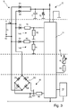
- an electromechanical drive 1 for actuating a movable wing 5 in the illustrated embodiment has a housing 3 in which evaluation and control electronics 2, an electric motor 22, the motor shaft 24 of which is operatively connected to the wing 5 via a power transmission device, so that a movement of the motor shaft 24 causes a movement of the wing 5, a mechanical energy store 28, which is charged by an opening movement of the wing 5 and discharged by a closing movement of the movable wing 5, and a braking device 20, through which the movement of the wing 5 can be braked by operating the electric motor 22 as a generator.
- the movement of the wing 5 at motor terminals K1, K2 of the electric motor 22 operated as a generator produces a movement-dependent output voltage U A which is applied to a braking circuit 18.
- the braking circuit 18 has at least one switching element designed as a field effect transistor FET, via which the motor terminals K1, K2 can be short-circuited.
- the mechanical energy store 28 is preferably designed as a spring and is charged with potential energy by manually opening the wing 5, which closes the released wing 5 again.
- the output voltage U A of the electric motor 22 operated as a generator is applied to a charging circuit 12, which stores electrical energy in a capacitor C for supplying energy to emergency control electronics 10.
- the housing 3 is mounted fixed to the wing on the upper left edge area of the movable wing 5.
- the motor shaft 24 of the electric motor 22 is coupled via a transmission 26 to an output shaft 27 which is coupled to a slide arm 7.
- the sliding arm 7 has a sliding block 7.1 at its free end. which is mounted in a slide rail that is fixed to the front panel 9 is performed.
- the electric motor 22 is preferably designed as a permanent magnetic excited direct current motor.
- the evaluation and control electronics 2 include, in addition to the emergency control electronics 10 with a first evaluation and control unit 11, a main control electronics 30 with a second evaluation and control unit 32 and a motor relay 34, which via a further switching element S1 designed as an opener with a Operating voltage U B is connected.
- a freewheeling diode D F is connected electrically in parallel with the motor relay 34.
- the motor relay 34 activates the emergency operation in the event of a power failure and / or in the event of an alarm, such as a fire alarm, via at least one relay contact 34.1.
- a relay contact 34.1 connects a first motor terminal K1 to the main control electronics 30 in normal operation and to the emergency control electronics 10, which includes the charging circuit 12, in emergency operation.
- a second motor terminal K2 is connected both to the emergency control electronics 10 and to the main control electronics 30.
- a second relay contact, not shown, of the motor relay 34 can connect the second motor terminal K2 to the main control electronics 30 in normal operation and to the emergency control electronics 10 in emergency operation.
- the two evaluation and control units 11, 32 are each designed as a microcontroller.
- the motor relay 34 is energized by the applied operating voltage U B , so that the relay contact 34.1 connects the first motor terminal K1 to the main control electronics 30.
- the electromechanical drive 1 moves the leaf 5 and opens the corresponding door in that the second evaluation and control unit 32 accelerates the electric motor 22 by applying an input voltage U E to the motor terminals K1, K2.
- the wing 5 is moved by means of electrical energy. If the leaf 5 is moved manually to open the door, the passer-by has to generate the energy that is stored as potential energy in the mechanical energy store 28. If the passer-by lets go of leaf 5, the stored energy closes the door. So that the wing 5 does not hit the closed position without braking, the main control electronics 30 can use the braking device 20. to dampen the closing protection of wing 5. That
- Switching element S1 can, for example, be designed as an electronic switch controlled by the second evaluation and control unit 32, for example as a field effect transistor.
- the main control electronics 30 can use the components of the emergency control electronics 10 to dampen the movement of the movable wing 5 even during normal operation.
- the second evaluation and control unit 32 can thus disconnect the motor relay 34 from the operating voltage by opening the switching element S1.
- the relay contact 34.1 changes to the de-energized switching state shown and connects the motor terminals K1, K2 with the emergency electronics 10 so that the first evaluation and control unit 11 can dampen the movement of the movable wing 5 via the braking circuit 18.
- the emergency control electronics 10 include the charging circuit 12 to which the output voltage U A is applied and which stores electrical energy in the capacitor C for supplying energy to the emergency control electronics 10. Depending on the polarity of the output voltage U A , this is applied to the storage capacitor C via a first diode D1 or via a second diode D2.
- a Zener diode D z limits the maximum voltage.
- the emergency control electronics 10 in the illustrated embodiment includes a first measuring circuit 14A with a third diode D3 and a voltage divider, which has a first ohmic resistor R1 and a second ohmic resistor R2.
- the first measuring circuit 14A detects an opening movement of the sash 5 based on the polarity of the third diode D3 and outputs a measured variable for determining the opening speed of the sash 5 to the first evaluation and control unit 11 at the tap between the first and second ohmic resistors R1, R2.
- the emergency control electronics 10 include a second measuring circuit 14B with a fourth diode D4 and a further voltage divider, which has a third ohmic resistor R3 and a fourth ohmic resistor R4.
- the second measuring circuit 14B recognizes a closing movement of the leaf 5 due to the polarity of the fourth diode D4 and transmits a measured variable for determining the closing speed of the leaf 5 to the first evaluation and measurement at the tap between the third and fourth ohmic resistors R3, R4 Control unit 11 off.
- a third measuring circuit 16 of the emergency control electronics 10 comprises a position sensor R P , which outputs a measured variable for determining a current opening angle and / or a current speed of the wing 5 to the first evaluation and control unit 11.
- the position sensor R p can be designed, for example, as a film potentiometer, to which a protective resistor R5 can be connected in series to limit the current.
- the first evaluation and control unit 11 can thus determine a current direction of movement and speed of the wing 5 from the output voltage U A via the measuring circuits 14A, 14B.
- the first evaluation and control unit 11 can determine the absolute opening angle or the speed of the wing 5 via the third measuring circuit 16.
- the braking circuit 18 comprises the field effect transistor FET, a gate resistor R6, via which the gate of the field effect transistor FET is electrically connected to the first evaluation and control unit 11, and a bridge rectifier circuit BG with four diodes D5, D6, D7, D8, which has the effect that the polarity of the voltage applied to the drain-source path of the field effect transistor FET remains the same regardless of the polarity of the output voltage U A of the electric motor 22 operated as a generator.
- the first evaluation and control unit 11 now controls the short circuit at the motor terminals K1, K2 via the field effect transistor FET according to the following principle: When the emergency mode is activated, the motor terminals K1, K2 are open and electrical energy is charged into the capacitor C of the charging circuit 12. The energy stored in the capacitor C is used to supply the emergency control electronics 10 with energy. In addition, while the motor terminals K1, K2 are open, the first evaluation and control unit 11 determines the angular speed of the electric motor 22, i.e. the speed of the wing 5, via the first or second measuring circuit 14A, 14B Measuring circle 16 determine the position or the speed of the wing 5.
- the first evaluation and control unit 11 closes the motor terminals K1. K2 briefly via the field effect transistor FET. During the short circuit the angular speed of the electric motor 22 is damped. Due to the pulse width modulation of the short-circuit current I A , the first evaluation and control unit 11 adjusts the damping of the speed and thus the braking force in emergency operation and ensures that its energy supply is recharged. In emergency mode, the first evaluation and control unit 11 adjusts the damping of the movement of the sash 5 depending on the current operating state of the electromechanical drive 1 and / or on a current direction of movement and / or a current speed and / or a current opening angle of the sash 5.
- the first evaluation and control unit 11 ensures the desired closing time of, for example, 5 seconds by regulating the closing speed as a function of the opening angle of the leaf 5.
- the closing time is therefore independent of temperature, aging and friction. This means that the first evaluation and control unit 11 adjusts the damping of the movement of the sash 5 as a function of a current operating state of the electric drive 1 and / or a current direction of movement and / or a current speed and / or a current opening angle of the sash 5 .
- the first evaluation and control unit 11 dampens an automatic opening movement of the sash 5 for a predetermined first period of time of, for example, approximately 3 seconds with a maximum braking force if emergency operation occurs during the automatic opening movement of the sash 5. After the predetermined first period of approximately 3 seconds has elapsed, the first evaluation and control unit 1 limits the further opening movement of the sash 5 to a maximum opening speed. If emergency operation occurs during the manual opening movement, the first evaluation and control unit 11 limits a manual opening movement of the sash 5 to a maximum opening speed. This can advantageously reduce the risk of the wing 5 striking the open position without braking or injuring a person behind the wing.
- the first evaluation and control unit 11 limits the closing movement of the wing 5 to a maximum Closing speed.
- the first evaluation and control unit 11 ends the damping of the closing movement of the sash 5 when the sash 5 has reached at least one predetermined end stop condition.
- a latching speed and / or a latching position can be specified as a latching condition.
- the second evaluation and control unit 32 of the main control electronics 30 communicates with the first evaluation and control unit 11 of the emergency control electronics 10 in normal operation via corresponding communication links and outputs information about the current operating state of the electromechanical drive 1 to the first evaluation and control unit 11.
- the second evaluation and control unit 32 can output parameters and / or limit values for damping the movement of the wing 5 to the first evaluation and control unit 11.
- the first evaluation and control unit 11 stores the parameters and / or limit values for damping the movement of the sash 5 in a non-volatile memory 19.
- the first evaluation and control unit 11 increments a counter in the non-volatile memory with each opening cycle of the sash 5 19.
- maintenance data can be written into the non-volatile data memory 19 and read from it. This also applies to the status of the cycle counter in the data memory 19.
- Embodiments of the electromechanical drive 1 according to the invention can preferably be used for fire doors.
- Emergency control electronics S1 Switching element 11 Evaluation and control unit (microcontroller) 12th Charging circuit (power supply) 14A first measuring circuit (speed measurement) 14B second measuring circuit (speed measurement) 16 third measuring circuit (position determination) 18th Braking circuit (pulse width modulation) 19th non-volatile memory 20th Braking device 22nd Electric motor 24 Motor shaft 26th transmission 27 Output shaft 28 mechanical energy storage 30th Main control electronics 32 Evaluation and control unit (microcontroller) 34 Motor relay 34.1 Relay contact D1 to D8 diode R1 to R6 ohmic resistance Rp Potentiometer C.
Landscapes
- Engineering & Computer Science (AREA)
- Power Engineering (AREA)
- Business, Economics & Management (AREA)
- Emergency Management (AREA)
- Power-Operated Mechanisms For Wings (AREA)
Claims (18)
- Entraînement électromécanique (1) comportant un moteur électrique (22) destiné à actionner un battant mobile (5) à l'aide du moteur électrique (22) dont l'arbre de moteur (24), dans l'état monté de l'entraînement (1), est en liaison fonctionnelle avec le battant (5) par le biais d'un élément de transmission de force, de sorte qu'un mouvement de l'arbre de moteur (24) provoque un mouvement du battant (5), un accumulateur d'énergie mécanique, lequel est chargé par un mouvement d'ouverture du battant (5) et est déchargé par un mouvement de fermeture du battant mobile (5), et un dispositif de freinage (20) au moyen duquel le mouvement du battant (5) peut être freiné, par le fait que le moteur électrique (22) peut fonctionner comme générateur, une tension de sortie (UA), dépendante du mouvement, étant produite aux bornes (K1, K2) du moteur électrique (22) fonctionnant comme générateur par le mouvement du battant (5), laquelle tension de sortie est appliquée à un circuit de courant de freinage (18), le circuit de courant de freinage (18) comprenant au moins un élément de commutation (FET) par le biais duquel les bornes de moteur (K1, K2) peuvent être mises en court-circuit,
caractérisé en ce que,dans un fonctionnement d'urgence, la tension de sortie (UA) du moteur électrique (22) fonctionnant comme générateur est appliquée à un circuit de charge (12), lequel stocke de l'énergie électrique dans un condensateur (C) pour l'alimentation en énergie d'une électronique de commande d'urgence (10),en outre une première unité d'évaluation et de commande (11) de l'électronique de commande d'urgence (10) réglant, par le biais de l'élément de commutation réalisé comme transistor à effet de champ (FET), une force de freinage effective pour l'amortissement du mouvement du battant (5) et la première unité d'évaluation et de commande (11) effectuant, par le biais du transistor à effet de champ (FET), une modulation d'impulsions en largeur du courant de moteur (IA). - Entraînement selon la revendication 1,
caractérisé en ce
qu'un relais motorisé (34) active le fonctionnement d'urgence par le biais d'au moins un contact de relais (34.1) en cas de panne de courant et/ou en cas d'alarme. - Entraînement selon la revendication 2,
caractérisé en ce que
l'au moins un contact de relais (34.1), dans le fonctionnement normal, connecte les bornes de moteur (K1, K2) à une électronique de commande principale (30) et, dans le fonctionnement d'urgence, à l'électronique de commande d'urgence (10), laquelle comporte le circuit de charge (12). - Entraînement selon l'une des revendications 1 à 3,
caractérisé en ce
qu'une deuxième unité d'évaluation et de commande (32) de l'électronique de commande principale (30), dans le fonctionnement normal, communique avec la première unité d'évaluation et de commande (11) de l'électronique de commande d'urgence (10) par le biais de connexions de communication correspondantes, et délivre à la première unité d'évaluation et de commande (11) des informations relatives à l'état de fonctionnement actuel de l'entraînement électromécanique (1). - Entraînement selon l'une des revendications 1 à 4,
caractérisé en ce que
la première unité d'évaluation et de commande (11) règle l'amortissement du mouvement du battant (5) en fonction de l'état de fonctionnement actuel de l'entraînement électromécanique (1) et/ou d'une direction de mouvement actuelle et/ou d'une vitesse actuelle et/ou d'un angle d'ouverture actuel du battant (5) . - Entraînement selon la revendication 5,
caractérisé en ce que
la première unité d'évaluation et de commande (11) détermine une direction de mouvement et une vitesse actuelles du battant (5) à partir de la tension de sortie (UA) par le biais d'au moins un circuit de mesure (14A, 14B) . - Entraînement selon la revendication 6,
caractérisé en ce
qu'au moins un premier circuit de mesure (14A) détecte un mouvement d'ouverture du battant (5) et délivre à la première unité d'évaluation et de commande (11) une grandeur de mesure servant à la détermination de la vitesse d'ouverture du battant (5). - Entraînement selon la revendication 6 ou 7,
caractérisé en ce
qu'au moins un deuxième circuit de mesure (14B) détecte un mouvement de fermeture du battant (5) et délivre à la première unité d'évaluation et de commande (11) une grandeur de mesure servant à la détermination de la vitesse de fermeture du battant (5). - Entraînement selon l'une des revendications 5 à 8,
caractérisé en ce
qu'au moins un troisième circuit de mesure (16) comporte un capteur de position (Rp), lequel délivre à la première unité d'évaluation et de commande (11) une grandeur de mesure servant à la détermination d'un angle d'ouverture actuel et/ou d'une vitesse actuelle du battant (5). - Entraînement selon l'une des revendications 1 à 9,
caractérisé en ce que
la première unité d'évaluation et de commande (11) amortit avec une force de freinage maximale un mouvement d'ouverture automatique du battant (5) pendant une première durée prédéfinie et, au terme de la première durée prédéfinie, limite le mouvement d'ouverture supplémentaire du battant (5) à une vitesse d'ouverture maximale si le fonctionnement d'urgence se produit pendant le mouvement d'ouverture automatique du battant (5) . - Entraînement selon l'une des revendications 1 à 10,
caractérisé en ce que
la première unité d'évaluation et de commande (11) limite un mouvement d'ouverture manuel du battant (5) à une vitesse d'ouverture maximale si le fonctionnement d'urgence se produit pendant le mouvement d'ouverture manuel. - Entraînement selon l'une des revendications 1 à 11,
caractérisé en ce que
la première unité d'évaluation et de commande (11) limite le mouvement de fermeture du battant (5) à une vitesse de fermeture maximale si le fonctionnement d'urgence se produit pendant le mouvement de fermeture. - Entraînement selon la revendication 12,
caractérisé en ce que
la première unité d'évaluation et de commande (11) met fin à l'amortissement du mouvement de fermeture du battant (5) si le battant (5) a atteint au moins une condition de butée de fin de course prédéfinie. - Entraînement selon la revendication 13,
caractérisé en ce
qu'une vitesse de butée de fin de course et/ou une position de butée de fin de course sont prédéfinies comme condition de butée de fin de course. - Entraînement selon l'une des revendications 4 à 14,
caractérisé en ce que
la deuxième unité d'évaluation et de commande (32) délivre à la première unité d'évaluation et de commande (11) des paramètres et/ou des valeurs limites pour l'amortissement du mouvement du battant (5). - Entraînement selon la revendication 15,
caractérisé en ce que
la première unité d'évaluation et de commande (11) stocke dans une mémoire non volatile (19) les paramètres et/ou valeurs limites pour l'amortissement du mouvement du battant (5). - Entraînement selon la revendication 15 ou 16,
caractérisé en ce que
la première unité d'évaluation et de commande (11) incrémente, à chaque cycle d'ouverture du battant (5), un compteur dans la mémoire non volatile (19). - Porte dotée d'au moins un battant mobile (5) et d'un entraînement électromécanique (1) destiné à actionner le battant mobile (5),
caractérisée en ce que
l'entraînement électromécanique (1) est réalisé selon au moins l'une des revendications 1 à 17.
Priority Applications (1)
| Application Number | Priority Date | Filing Date | Title |
|---|---|---|---|
| PL15804388T PL3245732T3 (pl) | 2015-01-13 | 2015-12-01 | Napęd elektromechaniczny do uruchamiania ruchomego skrzydła i odpowiednie drzwi |
Applications Claiming Priority (2)
| Application Number | Priority Date | Filing Date | Title |
|---|---|---|---|
| DE102015200289.6A DE102015200289B4 (de) | 2015-01-13 | 2015-01-13 | Elektromechanischer Antrieb zum Betätigen eines beweglichen Flügels und korrespondierende Tür |
| PCT/EP2015/078168 WO2016113031A1 (fr) | 2015-01-13 | 2015-12-01 | Entraînement électromécanique pour l'actionnement d'un battant mobile et porte correspondante |
Publications (2)
| Publication Number | Publication Date |
|---|---|
| EP3245732A1 EP3245732A1 (fr) | 2017-11-22 |
| EP3245732B1 true EP3245732B1 (fr) | 2021-09-29 |
Family
ID=54780277
Family Applications (1)
| Application Number | Title | Priority Date | Filing Date |
|---|---|---|---|
| EP15804388.5A Active EP3245732B1 (fr) | 2015-01-13 | 2015-12-01 | Entraînement électromécanique pour l'actionnement d'un battant mobile et porte correspondante |
Country Status (5)
| Country | Link |
|---|---|
| EP (1) | EP3245732B1 (fr) |
| DE (1) | DE102015200289B4 (fr) |
| DK (1) | DK3245732T3 (fr) |
| PL (1) | PL3245732T3 (fr) |
| WO (1) | WO2016113031A1 (fr) |
Cited By (2)
| Publication number | Priority date | Publication date | Assignee | Title |
|---|---|---|---|---|
| EP4350970A1 (fr) | 2022-10-07 | 2024-04-10 | dormakaba Deutschland GmbH | Procédé de détermination d'au moins une propriété d'un mouvement de rotation d'une machine triphasée en fonctionnement d'un générateur et entraînement électromécanique |
| EP4350971A1 (fr) | 2022-10-07 | 2024-04-10 | dormakaba Deutschland GmbH | Entraînement électromécanique destiné à actionner un battant monté mobile sur un élément structural |
Families Citing this family (10)
| Publication number | Priority date | Publication date | Assignee | Title |
|---|---|---|---|---|
| EP3104518B2 (fr) | 2015-06-10 | 2021-07-28 | Belimo Holding AG | Circuit de commande pour un entrainement de securite |
| DE102016202225A1 (de) * | 2016-02-15 | 2017-08-17 | Geze Gmbh | Bremsvorrichtung für einen beweglichen Türflügel und korrespondierender Türschließer |
| RU2754751C2 (ru) | 2016-12-07 | 2021-09-07 | Асса Аблой Энтранс Системс АБ | Автоматический открыватель двери для распашной двери в сборе |
| DE102017201944A1 (de) | 2017-02-08 | 2018-08-09 | Geze Gmbh | Bremsvorrichtung |
| DE102017201942A1 (de) | 2017-02-08 | 2018-08-09 | Geze Gmbh | Feststell- und/oder Notöffnungsanlage |
| DE102017201953A1 (de) * | 2017-02-08 | 2018-08-09 | Geze Gmbh | Antriebseinrichtung für einen Tür- oder Fensterflügel |
| DE102017201950A1 (de) * | 2017-02-08 | 2018-08-09 | Geze Gmbh | Bremsvorrichtung |
| DE102017103920B4 (de) | 2017-02-24 | 2025-06-18 | Rolf Petz | Stellantrieb |
| DE102017210434A1 (de) * | 2017-06-21 | 2018-12-27 | Geze Gmbh | Elektrischer Türantrieb und Sicherheitstür |
| DE102022108617A1 (de) | 2022-04-08 | 2023-10-12 | Brose Fahrzeugteile Se & Co. Kommanditgesellschaft, Bamberg | Antriebsanordnung zum motorischen Verstellen einer Klappe eines Kraftfahrzeugs |
Family Cites Families (7)
| Publication number | Priority date | Publication date | Assignee | Title |
|---|---|---|---|---|
| AU2002952885A0 (en) * | 2002-11-25 | 2002-12-12 | Turbocor Inc | High speed electric motor power supply |
| DE102005028007B4 (de) | 2005-06-16 | 2009-05-07 | Geze Gmbh | Antrieb zum Betätigen eines beweglichen Flügels, insbesondere einer Tür |
| DE102005049488B8 (de) * | 2005-10-13 | 2007-02-15 | Grass Gmbh | Vorrichtung und Verfahren zum Verschließen oder zum Öffnen und Schließen von wenigstens einer Schublade, Klappe, Tür oder dergleichen |
| JP5281513B2 (ja) * | 2009-07-30 | 2013-09-04 | シロキ工業株式会社 | 車両用開閉体の駆動装置 |
| DE102011004019B4 (de) | 2011-02-14 | 2015-02-12 | Siemens Aktiengesellschaft | Elektrisch angetriebene Tür |
| JP5993610B2 (ja) * | 2012-05-08 | 2016-09-14 | アズビル株式会社 | 電動アクチュエータ |
| EP3104518B2 (fr) * | 2015-06-10 | 2021-07-28 | Belimo Holding AG | Circuit de commande pour un entrainement de securite |
-
2015
- 2015-01-13 DE DE102015200289.6A patent/DE102015200289B4/de active Active
- 2015-12-01 EP EP15804388.5A patent/EP3245732B1/fr active Active
- 2015-12-01 DK DK15804388.5T patent/DK3245732T3/da active
- 2015-12-01 PL PL15804388T patent/PL3245732T3/pl unknown
- 2015-12-01 WO PCT/EP2015/078168 patent/WO2016113031A1/fr not_active Ceased
Cited By (4)
| Publication number | Priority date | Publication date | Assignee | Title |
|---|---|---|---|---|
| EP4350970A1 (fr) | 2022-10-07 | 2024-04-10 | dormakaba Deutschland GmbH | Procédé de détermination d'au moins une propriété d'un mouvement de rotation d'une machine triphasée en fonctionnement d'un générateur et entraînement électromécanique |
| EP4350971A1 (fr) | 2022-10-07 | 2024-04-10 | dormakaba Deutschland GmbH | Entraînement électromécanique destiné à actionner un battant monté mobile sur un élément structural |
| WO2024074644A1 (fr) | 2022-10-07 | 2024-04-11 | Dormakaba Deutschland Gmbh | Entraînement électromécanique pour actionner un châssis monté de manière mobile sur un élément de structure |
| US12560638B2 (en) | 2022-10-07 | 2026-02-24 | Dormakaba Deutschland Gmbh | Method for determining at least one property of a rotational movement of a three-phase rotary current machine in generator operation and electromechanical drive |
Also Published As
| Publication number | Publication date |
|---|---|
| EP3245732A1 (fr) | 2017-11-22 |
| PL3245732T3 (pl) | 2022-02-14 |
| DE102015200289A1 (de) | 2016-07-14 |
| DK3245732T3 (da) | 2021-11-22 |
| WO2016113031A1 (fr) | 2016-07-21 |
| DE102015200289B4 (de) | 2018-03-01 |
Similar Documents
| Publication | Publication Date | Title |
|---|---|---|
| EP3245732B1 (fr) | Entraînement électromécanique pour l'actionnement d'un battant mobile et porte correspondante | |
| EP3417135B1 (fr) | Dispositif de freinage d'un battant de porte mobile et dispositif de fermeture de porte correspondant | |
| EP3245728B1 (fr) | Dispositif de freinage d'un battant de porte mobile et dispositif de fermeture de porte correspondant | |
| EP0966782B1 (fr) | Procede de commande et de regulation electriques du deplacement d'unites actionnees electriquement | |
| EP2267881B1 (fr) | Circuit de freinage pour un actionneur de porte doté d'un moteur électrique fonctionnant comme générateur | |
| DE102013002245A1 (de) | Steuervorrichtung für Gleichstrommotor | |
| WO2010124927A2 (fr) | Procédé et dispositif permettant de détecter une situation de pincement | |
| DE102011107866A1 (de) | Verfahren zum Betrieb eines Gebäudeverschlusses | |
| DE102017201955A1 (de) | Bremsvorrichtung | |
| DE4318128A1 (de) | Verfahren zur elektronischen Überwachung und Steuerung des Öffnungs- und Schließvorganges von elektrisch betriebenen Aggregaten | |
| EP1941120B1 (fr) | Mecanisme d'entrainement destine a actionner un battant mobile, en particulier une porte | |
| DE102005028007B4 (de) | Antrieb zum Betätigen eines beweglichen Flügels, insbesondere einer Tür | |
| EP3361620B1 (fr) | Dispositif de freinage | |
| EP0468361B1 (fr) | Limitation de la force de fermeture à l'arête de fermeture d'un élément mobile | |
| DE102010010354B3 (de) | Fensterheberanordnung für ein Kraftfahrzeug | |
| DE10044029A1 (de) | Steueranordnung eines AC-Jalousienmotors oder eines AC-Rohrmotors | |
| EP3361621A1 (fr) | Dispositif de freinage | |
| DE102011107867B4 (de) | Verfahren zum Betrieb eines Gebäudeverschlusses | |
| EP3361034A1 (fr) | Installation d'ouverture fixe et/ou d'ouverture d'urgence | |
| DE102013103950B3 (de) | Tür, wie beispielsweise eine Drehtür, eine Karusselltür oder dergleichen, mit einem Elektromotor und eine Bremsschaltung für diese. | |
| EP3361027B1 (fr) | Dispositif de détermination | |
| DE10142431A1 (de) | Steuereinrichtung für Schnelllauftore | |
| DE102005044147A1 (de) | Verfahren zur Steuerung der Verstellbewegung einer elektromechanischen Verstellvorrichtung | |
| DE102016208596A1 (de) | Verfahren zum Betreiben einer Schließvorrichtung sowie eine Schließvorrichtung | |
| DE102013103478A1 (de) | Türantrieb |
Legal Events
| Date | Code | Title | Description |
|---|---|---|---|
| STAA | Information on the status of an ep patent application or granted ep patent |
Free format text: STATUS: THE INTERNATIONAL PUBLICATION HAS BEEN MADE |
|
| PUAI | Public reference made under article 153(3) epc to a published international application that has entered the european phase |
Free format text: ORIGINAL CODE: 0009012 |
|
| STAA | Information on the status of an ep patent application or granted ep patent |
Free format text: STATUS: REQUEST FOR EXAMINATION WAS MADE |
|
| 17P | Request for examination filed |
Effective date: 20170710 |
|
| AK | Designated contracting states |
Kind code of ref document: A1 Designated state(s): AL AT BE BG CH CY CZ DE DK EE ES FI FR GB GR HR HU IE IS IT LI LT LU LV MC MK MT NL NO PL PT RO RS SE SI SK SM TR |
|
| AX | Request for extension of the european patent |
Extension state: BA ME |
|
| RIN1 | Information on inventor provided before grant (corrected) |
Inventor name: FISCHER, MANUEL Inventor name: KATZ, EUGEN Inventor name: HUCKER, MATTHIAS Inventor name: HAEGELE, VOLKER Inventor name: HAHN, ERHARD |
|
| DAV | Request for validation of the european patent (deleted) | ||
| DAX | Request for extension of the european patent (deleted) | ||
| STAA | Information on the status of an ep patent application or granted ep patent |
Free format text: STATUS: EXAMINATION IS IN PROGRESS |
|
| 17Q | First examination report despatched |
Effective date: 20191203 |
|
| REG | Reference to a national code |
Ref country code: DE Ref legal event code: R079 Free format text: PREVIOUS MAIN CLASS: H02P0029020000 Ipc: E05F0015720000 |
|
| GRAP | Despatch of communication of intention to grant a patent |
Free format text: ORIGINAL CODE: EPIDOSNIGR1 |
|
| STAA | Information on the status of an ep patent application or granted ep patent |
Free format text: STATUS: GRANT OF PATENT IS INTENDED |
|
| RIC1 | Information provided on ipc code assigned before grant |
Ipc: H02P 3/14 20060101ALI20210416BHEP Ipc: H02P 3/12 20060101ALI20210416BHEP Ipc: H02P 29/024 20160101ALI20210416BHEP Ipc: E05F 15/72 20150101AFI20210416BHEP |
|
| INTG | Intention to grant announced |
Effective date: 20210517 |
|
| GRAS | Grant fee paid |
Free format text: ORIGINAL CODE: EPIDOSNIGR3 |
|
| GRAA | (expected) grant |
Free format text: ORIGINAL CODE: 0009210 |
|
| STAA | Information on the status of an ep patent application or granted ep patent |
Free format text: STATUS: THE PATENT HAS BEEN GRANTED |
|
| AK | Designated contracting states |
Kind code of ref document: B1 Designated state(s): AL AT BE BG CH CY CZ DK EE ES FI FR GB GR HR HU IE IS IT LI LT LU LV MC MK MT NL NO PL PT RO RS SE SI SK SM TR |
|
| RBV | Designated contracting states (corrected) |
Designated state(s): AL AT BE BG CH CY CZ DK EE ES FI FR GB GR HR HU IE IS IT LI LT LU LV MC MK MT NL NO PL PT RO RS SE SI SK SM TR |
|
| REG | Reference to a national code |
Ref country code: DE Ref legal event code: R108 Ref country code: GB Ref legal event code: FG4D Free format text: NOT ENGLISH |
|
| REG | Reference to a national code |
Ref country code: CH Ref legal event code: EP Ref country code: AT Ref legal event code: REF Ref document number: 1434336 Country of ref document: AT Kind code of ref document: T Effective date: 20211015 |
|
| REG | Reference to a national code |
Ref country code: IE Ref legal event code: FG4D Free format text: LANGUAGE OF EP DOCUMENT: GERMAN |
|
| REG | Reference to a national code |
Ref country code: DK Ref legal event code: T3 Effective date: 20211116 |
|
| REG | Reference to a national code |
Ref country code: NO Ref legal event code: T2 Effective date: 20210929 |
|
| REG | Reference to a national code |
Ref country code: LT Ref legal event code: MG9D |
|
| PG25 | Lapsed in a contracting state [announced via postgrant information from national office to epo] |
Ref country code: HR Free format text: LAPSE BECAUSE OF FAILURE TO SUBMIT A TRANSLATION OF THE DESCRIPTION OR TO PAY THE FEE WITHIN THE PRESCRIBED TIME-LIMIT Effective date: 20210929 Ref country code: SE Free format text: LAPSE BECAUSE OF FAILURE TO SUBMIT A TRANSLATION OF THE DESCRIPTION OR TO PAY THE FEE WITHIN THE PRESCRIBED TIME-LIMIT Effective date: 20210929 Ref country code: RS Free format text: LAPSE BECAUSE OF FAILURE TO SUBMIT A TRANSLATION OF THE DESCRIPTION OR TO PAY THE FEE WITHIN THE PRESCRIBED TIME-LIMIT Effective date: 20210929 Ref country code: LT Free format text: LAPSE BECAUSE OF FAILURE TO SUBMIT A TRANSLATION OF THE DESCRIPTION OR TO PAY THE FEE WITHIN THE PRESCRIBED TIME-LIMIT Effective date: 20210929 Ref country code: BG Free format text: LAPSE BECAUSE OF FAILURE TO SUBMIT A TRANSLATION OF THE DESCRIPTION OR TO PAY THE FEE WITHIN THE PRESCRIBED TIME-LIMIT Effective date: 20211229 Ref country code: FI Free format text: LAPSE BECAUSE OF FAILURE TO SUBMIT A TRANSLATION OF THE DESCRIPTION OR TO PAY THE FEE WITHIN THE PRESCRIBED TIME-LIMIT Effective date: 20210929 |
|
| REG | Reference to a national code |
Ref country code: NL Ref legal event code: MP Effective date: 20210929 |
|
| PG25 | Lapsed in a contracting state [announced via postgrant information from national office to epo] |
Ref country code: LV Free format text: LAPSE BECAUSE OF FAILURE TO SUBMIT A TRANSLATION OF THE DESCRIPTION OR TO PAY THE FEE WITHIN THE PRESCRIBED TIME-LIMIT Effective date: 20210929 Ref country code: GR Free format text: LAPSE BECAUSE OF FAILURE TO SUBMIT A TRANSLATION OF THE DESCRIPTION OR TO PAY THE FEE WITHIN THE PRESCRIBED TIME-LIMIT Effective date: 20211230 |
|
| PG25 | Lapsed in a contracting state [announced via postgrant information from national office to epo] |
Ref country code: IS Free format text: LAPSE BECAUSE OF FAILURE TO SUBMIT A TRANSLATION OF THE DESCRIPTION OR TO PAY THE FEE WITHIN THE PRESCRIBED TIME-LIMIT Effective date: 20220129 Ref country code: SK Free format text: LAPSE BECAUSE OF FAILURE TO SUBMIT A TRANSLATION OF THE DESCRIPTION OR TO PAY THE FEE WITHIN THE PRESCRIBED TIME-LIMIT Effective date: 20210929 Ref country code: RO Free format text: LAPSE BECAUSE OF FAILURE TO SUBMIT A TRANSLATION OF THE DESCRIPTION OR TO PAY THE FEE WITHIN THE PRESCRIBED TIME-LIMIT Effective date: 20210929 Ref country code: PT Free format text: LAPSE BECAUSE OF FAILURE TO SUBMIT A TRANSLATION OF THE DESCRIPTION OR TO PAY THE FEE WITHIN THE PRESCRIBED TIME-LIMIT Effective date: 20220131 Ref country code: NL Free format text: LAPSE BECAUSE OF FAILURE TO SUBMIT A TRANSLATION OF THE DESCRIPTION OR TO PAY THE FEE WITHIN THE PRESCRIBED TIME-LIMIT Effective date: 20210929 Ref country code: ES Free format text: LAPSE BECAUSE OF FAILURE TO SUBMIT A TRANSLATION OF THE DESCRIPTION OR TO PAY THE FEE WITHIN THE PRESCRIBED TIME-LIMIT Effective date: 20210929 Ref country code: EE Free format text: LAPSE BECAUSE OF FAILURE TO SUBMIT A TRANSLATION OF THE DESCRIPTION OR TO PAY THE FEE WITHIN THE PRESCRIBED TIME-LIMIT Effective date: 20210929 Ref country code: CZ Free format text: LAPSE BECAUSE OF FAILURE TO SUBMIT A TRANSLATION OF THE DESCRIPTION OR TO PAY THE FEE WITHIN THE PRESCRIBED TIME-LIMIT Effective date: 20210929 Ref country code: AL Free format text: LAPSE BECAUSE OF FAILURE TO SUBMIT A TRANSLATION OF THE DESCRIPTION OR TO PAY THE FEE WITHIN THE PRESCRIBED TIME-LIMIT Effective date: 20210929 |
|
| PG25 | Lapsed in a contracting state [announced via postgrant information from national office to epo] |
Ref country code: MC Free format text: LAPSE BECAUSE OF FAILURE TO SUBMIT A TRANSLATION OF THE DESCRIPTION OR TO PAY THE FEE WITHIN THE PRESCRIBED TIME-LIMIT Effective date: 20210929 |
|
| REG | Reference to a national code |
Ref country code: CH Ref legal event code: PL |
|
| PLBE | No opposition filed within time limit |
Free format text: ORIGINAL CODE: 0009261 |
|
| STAA | Information on the status of an ep patent application or granted ep patent |
Free format text: STATUS: NO OPPOSITION FILED WITHIN TIME LIMIT |
|
| GBPC | Gb: european patent ceased through non-payment of renewal fee |
Effective date: 20211229 |
|
| 26N | No opposition filed |
Effective date: 20220630 |
|
| REG | Reference to a national code |
Ref country code: BE Ref legal event code: MM Effective date: 20211231 |
|
| PG25 | Lapsed in a contracting state [announced via postgrant information from national office to epo] |
Ref country code: LU Free format text: LAPSE BECAUSE OF NON-PAYMENT OF DUE FEES Effective date: 20211201 Ref country code: IE Free format text: LAPSE BECAUSE OF NON-PAYMENT OF DUE FEES Effective date: 20211201 Ref country code: GB Free format text: LAPSE BECAUSE OF NON-PAYMENT OF DUE FEES Effective date: 20211229 |
|
| PG25 | Lapsed in a contracting state [announced via postgrant information from national office to epo] |
Ref country code: SI Free format text: LAPSE BECAUSE OF FAILURE TO SUBMIT A TRANSLATION OF THE DESCRIPTION OR TO PAY THE FEE WITHIN THE PRESCRIBED TIME-LIMIT Effective date: 20210929 Ref country code: FR Free format text: LAPSE BECAUSE OF NON-PAYMENT OF DUE FEES Effective date: 20211231 Ref country code: BE Free format text: LAPSE BECAUSE OF NON-PAYMENT OF DUE FEES Effective date: 20211231 |
|
| PG25 | Lapsed in a contracting state [announced via postgrant information from national office to epo] |
Ref country code: LI Free format text: LAPSE BECAUSE OF NON-PAYMENT OF DUE FEES Effective date: 20211231 Ref country code: CH Free format text: LAPSE BECAUSE OF NON-PAYMENT OF DUE FEES Effective date: 20211231 |
|
| PG25 | Lapsed in a contracting state [announced via postgrant information from national office to epo] |
Ref country code: HU Free format text: LAPSE BECAUSE OF FAILURE TO SUBMIT A TRANSLATION OF THE DESCRIPTION OR TO PAY THE FEE WITHIN THE PRESCRIBED TIME-LIMIT; INVALID AB INITIO Effective date: 20151201 |
|
| P01 | Opt-out of the competence of the unified patent court (upc) registered |
Effective date: 20230510 |
|
| PG25 | Lapsed in a contracting state [announced via postgrant information from national office to epo] |
Ref country code: CY Free format text: LAPSE BECAUSE OF FAILURE TO SUBMIT A TRANSLATION OF THE DESCRIPTION OR TO PAY THE FEE WITHIN THE PRESCRIBED TIME-LIMIT Effective date: 20210929 |
|
| PG25 | Lapsed in a contracting state [announced via postgrant information from national office to epo] |
Ref country code: SM Free format text: LAPSE BECAUSE OF FAILURE TO SUBMIT A TRANSLATION OF THE DESCRIPTION OR TO PAY THE FEE WITHIN THE PRESCRIBED TIME-LIMIT Effective date: 20210929 |
|
| PGFP | Annual fee paid to national office [announced via postgrant information from national office to epo] |
Ref country code: DK Payment date: 20231227 Year of fee payment: 9 Ref country code: AT Payment date: 20231221 Year of fee payment: 9 |
|
| PGFP | Annual fee paid to national office [announced via postgrant information from national office to epo] |
Ref country code: PL Payment date: 20231123 Year of fee payment: 9 |
|
| PG25 | Lapsed in a contracting state [announced via postgrant information from national office to epo] |
Ref country code: MK Free format text: LAPSE BECAUSE OF FAILURE TO SUBMIT A TRANSLATION OF THE DESCRIPTION OR TO PAY THE FEE WITHIN THE PRESCRIBED TIME-LIMIT Effective date: 20210929 |
|
| PG25 | Lapsed in a contracting state [announced via postgrant information from national office to epo] |
Ref country code: MT Free format text: LAPSE BECAUSE OF FAILURE TO SUBMIT A TRANSLATION OF THE DESCRIPTION OR TO PAY THE FEE WITHIN THE PRESCRIBED TIME-LIMIT Effective date: 20210929 |
|
| REG | Reference to a national code |
Ref country code: DK Ref legal event code: EBP Effective date: 20241231 |
|
| REG | Reference to a national code |
Ref country code: AT Ref legal event code: MM01 Ref document number: 1434336 Country of ref document: AT Kind code of ref document: T Effective date: 20241201 |
|
| PG25 | Lapsed in a contracting state [announced via postgrant information from national office to epo] |
Ref country code: AT Free format text: LAPSE BECAUSE OF NON-PAYMENT OF DUE FEES Effective date: 20241201 |
|
| PG25 | Lapsed in a contracting state [announced via postgrant information from national office to epo] |
Ref country code: TR Free format text: LAPSE BECAUSE OF FAILURE TO SUBMIT A TRANSLATION OF THE DESCRIPTION OR TO PAY THE FEE WITHIN THE PRESCRIBED TIME-LIMIT Effective date: 20210929 |
|
| PG25 | Lapsed in a contracting state [announced via postgrant information from national office to epo] |
Ref country code: DK Free format text: LAPSE BECAUSE OF NON-PAYMENT OF DUE FEES Effective date: 20241231 |
|
| PGFP | Annual fee paid to national office [announced via postgrant information from national office to epo] |
Ref country code: IT Payment date: 20251223 Year of fee payment: 11 |
|
| PGFP | Annual fee paid to national office [announced via postgrant information from national office to epo] |
Ref country code: NO Payment date: 20251230 Year of fee payment: 11 |
|
| PG25 | Lapsed in a contracting state [announced via postgrant information from national office to epo] |
Ref country code: PL Free format text: LAPSE BECAUSE OF NON-PAYMENT OF DUE FEES Effective date: 20241201 |