EP4350971A1 - Entraînement électromécanique destiné à actionner un battant monté mobile sur un élément structural - Google Patents
Entraînement électromécanique destiné à actionner un battant monté mobile sur un élément structural Download PDFInfo
- Publication number
- EP4350971A1 EP4350971A1 EP22200311.3A EP22200311A EP4350971A1 EP 4350971 A1 EP4350971 A1 EP 4350971A1 EP 22200311 A EP22200311 A EP 22200311A EP 4350971 A1 EP4350971 A1 EP 4350971A1
- Authority
- EP
- European Patent Office
- Prior art keywords
- control
- control device
- current
- wing
- electromechanical drive
- Prior art date
- Legal status (The legal status is an assumption and is not a legal conclusion. Google has not performed a legal analysis and makes no representation as to the accuracy of the status listed.)
- Pending
Links
Images

Classifications
-
- H—ELECTRICITY
- H02—GENERATION; CONVERSION OR DISTRIBUTION OF ELECTRIC POWER
- H02P—CONTROL OR REGULATION OF ELECTRIC MOTORS, ELECTRIC GENERATORS OR DYNAMO-ELECTRIC CONVERTERS; CONTROLLING TRANSFORMERS, REACTORS OR CHOKE COILS
- H02P29/00—Arrangements for regulating or controlling electric motors, appropriate for both AC and DC motors
- H02P29/02—Providing protection against overload without automatic interruption of supply
- H02P29/024—Detecting a fault condition, e.g. short circuit, locked rotor, open circuit or loss of load
- H02P29/025—Detecting a fault condition, e.g. short circuit, locked rotor, open circuit or loss of load the fault being a power interruption
-
- E—FIXED CONSTRUCTIONS
- E05—LOCKS; KEYS; WINDOW OR DOOR FITTINGS; SAFES
- E05F—DEVICES FOR MOVING WINGS INTO OPEN OR CLOSED POSITION; CHECKS FOR WINGS; WING FITTINGS NOT OTHERWISE PROVIDED FOR, CONCERNED WITH THE FUNCTIONING OF THE WING
- E05F1/00—Closers or openers for wings, not otherwise provided for in this subclass
- E05F1/002—Closers or openers for wings, not otherwise provided for in this subclass controlled by automatically acting means
- E05F1/006—Closers or openers for wings, not otherwise provided for in this subclass controlled by automatically acting means by emergency conditions, e.g. fire
-
- E—FIXED CONSTRUCTIONS
- E05—LOCKS; KEYS; WINDOW OR DOOR FITTINGS; SAFES
- E05F—DEVICES FOR MOVING WINGS INTO OPEN OR CLOSED POSITION; CHECKS FOR WINGS; WING FITTINGS NOT OTHERWISE PROVIDED FOR, CONCERNED WITH THE FUNCTIONING OF THE WING
- E05F1/00—Closers or openers for wings, not otherwise provided for in this subclass
- E05F1/08—Closers or openers for wings, not otherwise provided for in this subclass spring-actuated, e.g. for horizontally sliding wings
- E05F1/10—Closers or openers for wings, not otherwise provided for in this subclass spring-actuated, e.g. for horizontally sliding wings for swinging wings, e.g. counterbalance
- E05F1/1041—Closers or openers for wings, not otherwise provided for in this subclass spring-actuated, e.g. for horizontally sliding wings for swinging wings, e.g. counterbalance with a coil spring perpendicular to the pivot axis
-
- E—FIXED CONSTRUCTIONS
- E05—LOCKS; KEYS; WINDOW OR DOOR FITTINGS; SAFES
- E05F—DEVICES FOR MOVING WINGS INTO OPEN OR CLOSED POSITION; CHECKS FOR WINGS; WING FITTINGS NOT OTHERWISE PROVIDED FOR, CONCERNED WITH THE FUNCTIONING OF THE WING
- E05F15/00—Power-operated mechanisms for wings
- E05F15/60—Power-operated mechanisms for wings using electrical actuators
- E05F15/603—Power-operated mechanisms for wings using electrical actuators using rotary electromotors
- E05F15/611—Power-operated mechanisms for wings using electrical actuators using rotary electromotors for swinging wings
- E05F15/63—Power-operated mechanisms for wings using electrical actuators using rotary electromotors for swinging wings operated by swinging arms
-
- E—FIXED CONSTRUCTIONS
- E05—LOCKS; KEYS; WINDOW OR DOOR FITTINGS; SAFES
- E05F—DEVICES FOR MOVING WINGS INTO OPEN OR CLOSED POSITION; CHECKS FOR WINGS; WING FITTINGS NOT OTHERWISE PROVIDED FOR, CONCERNED WITH THE FUNCTIONING OF THE WING
- E05F15/00—Power-operated mechanisms for wings
- E05F15/70—Power-operated mechanisms for wings with automatic actuation
- E05F15/72—Power-operated mechanisms for wings with automatic actuation responsive to emergency conditions, e.g. fire
-
- E—FIXED CONSTRUCTIONS
- E05—LOCKS; KEYS; WINDOW OR DOOR FITTINGS; SAFES
- E05F—DEVICES FOR MOVING WINGS INTO OPEN OR CLOSED POSITION; CHECKS FOR WINGS; WING FITTINGS NOT OTHERWISE PROVIDED FOR, CONCERNED WITH THE FUNCTIONING OF THE WING
- E05F3/00—Closers or openers with braking devices, e.g. checks; Construction of pneumatic or liquid braking devices
- E05F3/04—Closers or openers with braking devices, e.g. checks; Construction of pneumatic or liquid braking devices with liquid piston brakes
- E05F3/10—Closers or openers with braking devices, e.g. checks; Construction of pneumatic or liquid braking devices with liquid piston brakes with a spring, other than a torsion spring, and a piston, the axes of which are the same or lie in the same direction
-
- H—ELECTRICITY
- H02—GENERATION; CONVERSION OR DISTRIBUTION OF ELECTRIC POWER
- H02P—CONTROL OR REGULATION OF ELECTRIC MOTORS, ELECTRIC GENERATORS OR DYNAMO-ELECTRIC CONVERTERS; CONTROLLING TRANSFORMERS, REACTORS OR CHOKE COILS
- H02P29/00—Arrangements for regulating or controlling electric motors, appropriate for both AC and DC motors
- H02P29/02—Providing protection against overload without automatic interruption of supply
- H02P29/024—Detecting a fault condition, e.g. short circuit, locked rotor, open circuit or loss of load
- H02P29/028—Detecting a fault condition, e.g. short circuit, locked rotor, open circuit or loss of load the motor continuing operation despite the fault condition, e.g. eliminating, compensating for or remedying the fault
-
- H—ELECTRICITY
- H02—GENERATION; CONVERSION OR DISTRIBUTION OF ELECTRIC POWER
- H02P—CONTROL OR REGULATION OF ELECTRIC MOTORS, ELECTRIC GENERATORS OR DYNAMO-ELECTRIC CONVERTERS; CONTROLLING TRANSFORMERS, REACTORS OR CHOKE COILS
- H02P3/00—Arrangements for stopping or slowing electric motors, generators, or dynamo-electric converters
- H02P3/06—Arrangements for stopping or slowing electric motors, generators, or dynamo-electric converters for stopping or slowing an individual dynamo-electric motor or dynamo-electric converter
- H02P3/18—Arrangements for stopping or slowing electric motors, generators, or dynamo-electric converters for stopping or slowing an individual dynamo-electric motor or dynamo-electric converter for stopping or slowing an AC motor
- H02P3/22—Arrangements for stopping or slowing electric motors, generators, or dynamo-electric converters for stopping or slowing an individual dynamo-electric motor or dynamo-electric converter for stopping or slowing an AC motor by short-circuit or resistive braking
-
- E—FIXED CONSTRUCTIONS
- E05—LOCKS; KEYS; WINDOW OR DOOR FITTINGS; SAFES
- E05F—DEVICES FOR MOVING WINGS INTO OPEN OR CLOSED POSITION; CHECKS FOR WINGS; WING FITTINGS NOT OTHERWISE PROVIDED FOR, CONCERNED WITH THE FUNCTIONING OF THE WING
- E05F15/00—Power-operated mechanisms for wings
- E05F15/70—Power-operated mechanisms for wings with automatic actuation
-
- E—FIXED CONSTRUCTIONS
- E05—LOCKS; KEYS; WINDOW OR DOOR FITTINGS; SAFES
- E05F—DEVICES FOR MOVING WINGS INTO OPEN OR CLOSED POSITION; CHECKS FOR WINGS; WING FITTINGS NOT OTHERWISE PROVIDED FOR, CONCERNED WITH THE FUNCTIONING OF THE WING
- E05F15/00—Power-operated mechanisms for wings
- E05F15/60—Power-operated mechanisms for wings using electrical actuators
- E05F15/603—Power-operated mechanisms for wings using electrical actuators using rotary electromotors
- E05F15/611—Power-operated mechanisms for wings using electrical actuators using rotary electromotors for swinging wings
- E05F15/63—Power-operated mechanisms for wings using electrical actuators using rotary electromotors for swinging wings operated by swinging arms
- E05F2015/631—Power-operated mechanisms for wings using electrical actuators using rotary electromotors for swinging wings operated by swinging arms the end of the arm sliding in a track; Slider arms therefor
-
- E—FIXED CONSTRUCTIONS
- E05—LOCKS; KEYS; WINDOW OR DOOR FITTINGS; SAFES
- E05Y—INDEXING SCHEME ASSOCIATED WITH SUBCLASSES E05D AND E05F, RELATING TO CONSTRUCTION ELEMENTS, ELECTRIC CONTROL, POWER SUPPLY, POWER SIGNAL OR TRANSMISSION, USER INTERFACES, MOUNTING OR COUPLING, DETAILS, ACCESSORIES, AUXILIARY OPERATIONS NOT OTHERWISE PROVIDED FOR, APPLICATION THEREOF
- E05Y2201/00—Constructional elements; Accessories therefor
- E05Y2201/20—Brakes; Disengaging means; Holders; Stops; Valves; Accessories therefor
- E05Y2201/21—Brakes
-
- E—FIXED CONSTRUCTIONS
- E05—LOCKS; KEYS; WINDOW OR DOOR FITTINGS; SAFES
- E05Y—INDEXING SCHEME ASSOCIATED WITH SUBCLASSES E05D AND E05F, RELATING TO CONSTRUCTION ELEMENTS, ELECTRIC CONTROL, POWER SUPPLY, POWER SIGNAL OR TRANSMISSION, USER INTERFACES, MOUNTING OR COUPLING, DETAILS, ACCESSORIES, AUXILIARY OPERATIONS NOT OTHERWISE PROVIDED FOR, APPLICATION THEREOF
- E05Y2201/00—Constructional elements; Accessories therefor
- E05Y2201/40—Motors; Magnets; Springs; Weights; Accessories therefor
- E05Y2201/404—Function thereof
- E05Y2201/408—Function thereof for braking
-
- E—FIXED CONSTRUCTIONS
- E05—LOCKS; KEYS; WINDOW OR DOOR FITTINGS; SAFES
- E05Y—INDEXING SCHEME ASSOCIATED WITH SUBCLASSES E05D AND E05F, RELATING TO CONSTRUCTION ELEMENTS, ELECTRIC CONTROL, POWER SUPPLY, POWER SIGNAL OR TRANSMISSION, USER INTERFACES, MOUNTING OR COUPLING, DETAILS, ACCESSORIES, AUXILIARY OPERATIONS NOT OTHERWISE PROVIDED FOR, APPLICATION THEREOF
- E05Y2400/00—Electronic control; Electrical power; Power supply; Power or signal transmission; User interfaces
- E05Y2400/10—Electronic control
- E05Y2400/30—Electronic control of motors
- E05Y2400/302—Electronic control of motors during electric motor braking
-
- E—FIXED CONSTRUCTIONS
- E05—LOCKS; KEYS; WINDOW OR DOOR FITTINGS; SAFES
- E05Y—INDEXING SCHEME ASSOCIATED WITH SUBCLASSES E05D AND E05F, RELATING TO CONSTRUCTION ELEMENTS, ELECTRIC CONTROL, POWER SUPPLY, POWER SIGNAL OR TRANSMISSION, USER INTERFACES, MOUNTING OR COUPLING, DETAILS, ACCESSORIES, AUXILIARY OPERATIONS NOT OTHERWISE PROVIDED FOR, APPLICATION THEREOF
- E05Y2400/00—Electronic control; Electrical power; Power supply; Power or signal transmission; User interfaces
- E05Y2400/10—Electronic control
- E05Y2400/45—Control modes
-
- E—FIXED CONSTRUCTIONS
- E05—LOCKS; KEYS; WINDOW OR DOOR FITTINGS; SAFES
- E05Y—INDEXING SCHEME ASSOCIATED WITH SUBCLASSES E05D AND E05F, RELATING TO CONSTRUCTION ELEMENTS, ELECTRIC CONTROL, POWER SUPPLY, POWER SIGNAL OR TRANSMISSION, USER INTERFACES, MOUNTING OR COUPLING, DETAILS, ACCESSORIES, AUXILIARY OPERATIONS NOT OTHERWISE PROVIDED FOR, APPLICATION THEREOF
- E05Y2400/00—Electronic control; Electrical power; Power supply; Power or signal transmission; User interfaces
- E05Y2400/10—Electronic control
- E05Y2400/52—Safety arrangements associated with the wing motor
- E05Y2400/53—Wing impact prevention or reduction
- E05Y2400/532—Emergency braking or blocking
-
- E—FIXED CONSTRUCTIONS
- E05—LOCKS; KEYS; WINDOW OR DOOR FITTINGS; SAFES
- E05Y—INDEXING SCHEME ASSOCIATED WITH SUBCLASSES E05D AND E05F, RELATING TO CONSTRUCTION ELEMENTS, ELECTRIC CONTROL, POWER SUPPLY, POWER SIGNAL OR TRANSMISSION, USER INTERFACES, MOUNTING OR COUPLING, DETAILS, ACCESSORIES, AUXILIARY OPERATIONS NOT OTHERWISE PROVIDED FOR, APPLICATION THEREOF
- E05Y2800/00—Details, accessories and auxiliary operations not otherwise provided for
- E05Y2800/25—Emergency conditions
-
- E—FIXED CONSTRUCTIONS
- E05—LOCKS; KEYS; WINDOW OR DOOR FITTINGS; SAFES
- E05Y—INDEXING SCHEME ASSOCIATED WITH SUBCLASSES E05D AND E05F, RELATING TO CONSTRUCTION ELEMENTS, ELECTRIC CONTROL, POWER SUPPLY, POWER SIGNAL OR TRANSMISSION, USER INTERFACES, MOUNTING OR COUPLING, DETAILS, ACCESSORIES, AUXILIARY OPERATIONS NOT OTHERWISE PROVIDED FOR, APPLICATION THEREOF
- E05Y2800/00—Details, accessories and auxiliary operations not otherwise provided for
- E05Y2800/25—Emergency conditions
- E05Y2800/252—Emergency conditions the elements functioning only in case of emergency
-
- E—FIXED CONSTRUCTIONS
- E05—LOCKS; KEYS; WINDOW OR DOOR FITTINGS; SAFES
- E05Y—INDEXING SCHEME ASSOCIATED WITH SUBCLASSES E05D AND E05F, RELATING TO CONSTRUCTION ELEMENTS, ELECTRIC CONTROL, POWER SUPPLY, POWER SIGNAL OR TRANSMISSION, USER INTERFACES, MOUNTING OR COUPLING, DETAILS, ACCESSORIES, AUXILIARY OPERATIONS NOT OTHERWISE PROVIDED FOR, APPLICATION THEREOF
- E05Y2900/00—Application of doors, windows, wings or fittings thereof
- E05Y2900/10—Application of doors, windows, wings or fittings thereof for buildings or parts thereof
- E05Y2900/13—Type of wing
- E05Y2900/132—Doors
-
- E—FIXED CONSTRUCTIONS
- E05—LOCKS; KEYS; WINDOW OR DOOR FITTINGS; SAFES
- E05Y—INDEXING SCHEME ASSOCIATED WITH SUBCLASSES E05D AND E05F, RELATING TO CONSTRUCTION ELEMENTS, ELECTRIC CONTROL, POWER SUPPLY, POWER SIGNAL OR TRANSMISSION, USER INTERFACES, MOUNTING OR COUPLING, DETAILS, ACCESSORIES, AUXILIARY OPERATIONS NOT OTHERWISE PROVIDED FOR, APPLICATION THEREOF
- E05Y2900/00—Application of doors, windows, wings or fittings thereof
- E05Y2900/10—Application of doors, windows, wings or fittings thereof for buildings or parts thereof
- E05Y2900/13—Type of wing
- E05Y2900/148—Windows
Definitions
- the invention relates to an electromechanical drive for actuating a wing movably mounted on a structural element, in particular a door wing or a window wing, wherein the electromechanical drive has an electric motor with at least one phase, wherein a voltage curve over this phase is continuous during operation of the electric motor, wherein a drive shaft of the electric motor is operatively connected to the wing via a power transmission device when the electromechanical drive is mounted as intended on the wing and/or the frame, so that a movement of the drive shaft causes a movement of the wing, wherein the electromechanical drive has a mechanical energy store which is charged by an opening movement of the wing and discharged by a closing movement of the wing, so that the closing movement is triggered and/or supported by the energy stored in the mechanical energy store.
- Electromechanical drives for moving a wing are known from the state of the art.
- a wing is understood to mean a door or window wing in particular.
- Such wings are mounted in the structural elements surrounding the wing, such as frames.
- the wing is therefore the moving part and the structural element is the fixed part.
- the term frame can therefore also refer to any other structural element surrounding the wing, in particular a building wall.
- Such electromechanical drives often have an electric motor and a mechanical locking unit.
- the mechanical locking unit can be, for example, a spring that is tensioned by the electric motor when the wing is opened or when the wing is moved in an opening direction. The energy stored in the spring is used to close the wing. used. During the closing process, the electric motor can be used to slow down the wing movement.
- the sash should be reliably braked. This applies not only to the closing process, but also to the manual opening process in the event of a fault, in order to avoid an uncontrolled impact in the opening end position.
- the object of the invention is to further develop the electromechanical drives known from the prior art in such a way that safe operation is possible in the event of a fault.
- the electromechanical drive has an emergency braking device by means of which the movement of the wing can be braked in an operating state suitable for emergencies by operating the electric motor as a generator, wherein the movement of the wing causes a movement-dependent voltage to be applied between phase terminals of the electric motor operated as a generator, wherein the phase terminals are electrically connected to a braking circuit of the emergency braking device, wherein the emergency braking device has a control energy generating device, wherein the control energy generating device generates electrical energy for operating a control device of the emergency braking device that controls the braking circuit from an electrical current flowing between the phase terminals, wherein the control energy generating device is electrically connected to the control device, wherein the braking circuit has a current control device by means of which a current flow through the braking circuit and thereby between the phase terminals can be adjusted, and wherein the control device is electrically connected to the current control device in order to specify the braking effect exerted on the wing by the emergency braking device.
- the emergency braking device is designed in such a way that, in particular in the event of a power failure, the control device is supplied with electrical energy from the electrical energy generated by the movement of the wing. In this way, when the wing moves, the control device can control the current control device of the braking circuit in such a way that a desired maximum braking effect is achieved by adjusting the current flowing between the phase terminals of the electric motor. If the wing does not move, there is no voltage between the phase terminals, so that the power generation device cannot provide electrical energy to operate the control device and the control device cannot be operated. However, since the control device is only intended and required for the controlled braking process, this is not a disadvantage.
- the electric motor is a three-phase or alternating current electric motor
- the braking circuit has a braking rectifier circuit, wherein the braking rectifier circuit is electrically connected to the phase terminals of the electric motor operated as a generator.
- the alternating current or three-phase electric motor generates a single-phase or multi-phase electrical alternating voltage between the mutually associated phase terminals of the electric motor.
- the braking or short-circuit current flowing via the braking circuit between the phase terminals can be adjusted particularly easily, for example by using a MOSFET in the braking circuit according to the invention.
- the invention provides that the control energy generating device has a control rectifier circuit, wherein the control rectifier circuit is electrically connected to the phase terminals of the electric motor operated as a generator.
- the electrical energy for operating the control device can be generated particularly easily directly via the control rectifier circuit from the electrical voltage present between the phase terminals.
- a direct current is advantageous for operating the control device, since this can be used to operate conventional electronic circuit elements such as microcontrollers. Since the control rectifier circuit rectifies the alternating voltage present between the phase terminals, the electrical energy provided by the control rectifier circuit can be made available directly to other electronic circuit components.
- the control rectifier circuit is designed such that a voltage polarity of the movement-dependent voltage between the phase terminals, which depends on a direction of movement of the wing, is rectified to operate the control device.
- the invention provides that the control rectifier circuit and the brake rectifier circuit are electrically connected in parallel to one another with the phase terminals.
- the respective advantages can be combined with one another.
- a particularly simple structure of the brake rectifier circuit or the control rectifier circuit can be achieved by designing the control rectifier circuit and/or the brake rectifier circuit as a bridge rectifier circuit.
- the bridge rectifier circuit is also referred to as a two-pulse bridge rectifier circuit and has two pairs of diodes connected in parallel. The phase terminals are electrically connected between the pairs of diodes to the bridge rectifier circuit.
- the invention provides that the structure of the control rectifier circuit and the structure of the brake rectifier circuit are identical. "Identical” in this context means that an identical structure of the rectifier circuits is selected with components that have at least very similar characteristics. If bridge rectifier circuits are used, the diodes used should have properties that are as similar as possible.
- a maximum braking effect by the electric motor is achieved if the braking current flowing between the phase terminals is not limited by the current control device. This corresponds to a hard Phase short circuit. In this case, an output voltage across the brake rectifier circuit is approximately 0V.
- the voltage drop across the diodes of the brake rectifier circuit is relatively large due to the high braking current. If diodes with a similar characteristic to the brake rectifier circuit are used for the control rectifier circuit and the current flowing through the control device is lower than the braking current flowing through the brake rectifier circuit, the voltage drop across the diodes of the control rectifier circuit is also lower. This voltage difference can be used as the output voltage of the control rectifier circuit for the control device.
- the control energy generation device has a voltage drop element, wherein the voltage drop element is electrically connected to the brake rectifier circuit and the current control device, wherein the control device is electrically connected to the brake rectifier circuit and the current control device in parallel to the voltage drop element.
- the voltage drop element can, for example, be an ohmic resistance element with a predetermined electrical resistance that is connected in series with the brake rectifier circuit and the current control device. As soon as current flows through the current control device, a current-dependent, defined voltage drops across the resistance element, which can be used to supply the control device.
- the invention provides that the control energy generation device is electrically connected to the current control device in a parallel circuit.
- the current control device already contains electrical elements via which a voltage drop is generated that can be used to operate the control device.
- the A current measuring resistor can advantageously be provided in the current control device, which can also be used as a voltage drop element.
- the current control device is designed in such a way that a current flow through the brake rectifier circuit and the current control device is always greater than a current flow minimum when the wing moves.
- an electrical current flows through the brake circuit at all times when the wing moves, through which sufficient energy can be provided to operate the control device via the voltage drop element.
- the invention provides that the control device has a central control unit.
- the central control unit is advantageously an electronic and particularly advantageously a digital-electronic data processing device.
- a microcontroller is advantageously used as the central control device.
- Microcontrollers offer electrical inputs and outputs with digital-analog and analog-digital converters, PWM outputs and comparator inputs, so that the necessary calculations can be carried out, the electrical signals for controlling the current control device can be generated and measurement signals can be processed simultaneously with a microcontroller.
- the current control device comprises a transistor, a current measuring element and a control element, wherein the transistor is electrically connected to the brake rectifier circuit via a collector and an emitter, wherein a current flowing through the transistor is measured by the current measuring element, and wherein the control element is electrically connected to a base of the transistor in order to specify the current flow through the transistor, wherein the control element is electrically connected to the central control unit of the Control device is connected, wherein the control device specifies a current setpoint to the control element, wherein the control element is electrically conductively connected to the current measuring element, wherein the control element limits a current flow such that the current setpoint and the current match.
- the transistor is advantageously a MOSFET.
- a shunt resistor can advantageously be used as the current measuring element.
- An operational amplifier can advantageously be used as the control element. The operational amplifier compares the current value flowing through the MOSFET and the shunt resistor with a current setpoint specified by the control device. If the current flowing is too high, the gate voltage of the MOSFET is reduced by the operational amplifier until the current setpoint is reached. If the current flowing is too small, the gate voltage of the MOSFET is increased by the operational amplifier until the current setpoint is reached. The MOSFET is therefore used in linear operation. This circuit generates a constant load current between the phase terminals, provided the electric motor can supply it. Otherwise, the load current is limited by the maximum current flow that the electric motor can generate.
- the invention provides that a level converter is arranged between the central control unit and the control element.
- a low potential of the brake rectifier circuit moves away from a reference potential used for the control as the braking current increases.
- the voltage difference between these potentials can influence the current control device, so that without an additional circuit part the effective current setpoint specified by the control device would be dependent on the braking current and control would not be possible.
- the level converter can be used to convert the current setpoint generated by the control device or the reference potential used for control into a reference potential.
- Control voltage can be converted into a differential output voltage so that the control voltage of the control element is independent of the braking current.
- the invention provides that the control device has overvoltage protection, wherein the overvoltage protection is directly electrically connected to the control energy generation device.
- the overvoltage protection is directly electrically connected to the control energy generation device.
- an output voltage of the control rectifier circuit could correspond to the no-load voltage of the electric motor.
- this output voltage could be too high for the operation of the control device and could damage it.
- Overvoltage protection offers the possibility of limiting the output voltage generated by the control energy generation device to a range that is safe for the operation of the control device.
- the invention provides that the control device has a voltage regulator, wherein the voltage regulator is electrically connected to the current control device and supplies the current control device with electrical energy, and wherein the voltage regulator is electrically connected to other components of the control device and supplies them with electrical energy.
- the output voltage generated, for example, with a control rectifier circuit is too small in many applications for the operation of the control device.
- the voltage regulator which can be designed, for example, as a switching regulator, an operating voltage sufficient for the operation of the control device can be generated from the output voltage.
- the invention provides that the control device has a linear regulator, wherein the linear regulator is arranged in an electrically conductive manner between the voltage regulator and the other components of the control device.
- the invention provides that the control device has a measuring device for detecting the speed and direction of movement of the wing.
- the measuring device can advantageously comprise Hall sensors for detecting rotational movement parameters of the electric motor. These can advantageously be processed by the central control device.
- the existing inputs of the microcontroller can be used for this purpose.
- the invention provides that the electric motor is an axial flux motor or a radial flux motor.
- Axial or radial flux machines are particularly suitable for use with door or window drives.
- the electromechanical drive consists of the three-phase motor and the emergency braking device, wherein the emergency braking device consists of the control energy generating device, the control device and the braking circuit, wherein the control energy generating device consists of the control rectifier circuit, wherein the control device consists of the control element, the level converter, the overvoltage protection, the voltage regulator, the linear regulator, the measuring device and the central control unit, wherein the braking circuit consists of the current control device and the braking rectifier circuit, and wherein the current control device consists of the transistor, the current measuring element and the control element.
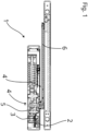
- FIG 1 is a schematic sectional view of an electromechanical drive 1 for actuating a wing, in particular a door wing or a window wing, which is mounted rotatably and/or displaceably on a structural element.
- the electromechanical drive 1 has a three-phase three-phase motor 2, which is designed as an axial flow machine.
- a drive shaft 3 of the three-phase motor 2 is operatively connected to the wing (not shown) via a power transmission device 4.
- the power transmission device 4 essentially consists of a gear 5 connected to the three-phase motor 2 and a lever 6. This converts a movement of the drive shaft 3 in motor mode of the three-phase motor 2 into a movement of the wing.
- a movement of the wing in generator mode of the three-phase motor 2 causes a movement of the drive shaft 3 via the power transmission device 4.
- the electromechanical drive 1 also has a Figure 1 not recognizable but in Figure 2 The emergency braking device 7 is shown in detail.
- the emergency braking device 7 can be used to brake the movement of the wing in an operating state suitable for emergencies by operating the three-phase motor 2 as a generator. As a result of the movement of the wing, a movement-dependent voltage is applied between phase terminals 8 of the three-phase motor 2 operated as a generator. The phase terminals 8 are electrically connected to a braking circuit 9 of the emergency braking device 7.
- the emergency braking device 7 has a control energy generating device 10.
- the control energy generating device 10 generates electrical energy for operating a control device 11 of the emergency braking device 7, which controls the braking circuit 9, from an electrical current flowing between the phase terminals 8.
- the control energy generating device 10 is electrically connected to the control device 11.
- the braking circuit 9 has a current control device 12, by means of which a current flow through the braking circuit 9 and thus between the phase terminals 8 can be adjusted.
- the control device 11 is electrically connected to the current control device 12 in order to specify the braking effect exerted on the wing by the emergency braking device 7.
- the braking circuit 9 also has a brake rectifier circuit 13 designed as a bridge rectifier circuit.
- the brake rectifier circuit 13 is electrically connected to the phase terminals 8 of the three-phase motor 2 operated as a generator.
- the control energy generation device 10 has a control rectifier circuit 14 which is also designed as a bridge rectifier circuit.
- the control rectifier circuit 14 is also electrically connected to the phase terminals 8 of the three-phase motor 2 operated as a generator in parallel to the brake rectifier circuit 13.
- the control device 11 has a central control unit 15.
- the central control unit 15 is a microcontroller.
- the current control device 12 comprises a transistor 16 designed as a MOSFET, a current measuring element 17 designed as a shunt resistor and a control element 18 designed as an operational amplifier.
- the transistor 16 is electrically connected to the brake rectifier circuit 13 via a collector and an emitter.
- the control element 18 is electrically connected to a base of the transistor 16 in order to specify the current flow through the transistor 16.
- the control element 18 is also electrically connected to the central control unit 15 of the control device 11.
- the control device 11 specifies a current setpoint value for the control element 18.
- the control element 18 is also electrically connected to the current measuring element 17.
- the current measuring element 17 measures a current flowing through the transistor 16.
- the control element 18 limits a current flow between the phase terminals 8 so that the current setpoint and the current flow match.
- a level converter 19 is arranged between the central control unit 15 and the control element 18.
- the control device 11 also has an overvoltage protection 20, which is directly electrically connected to the control energy generation device 10.
- the control device 13 also has a voltage regulator 21 and a linear regulator 22, which are electrically connected to the current control device 12 and supply the current control device 12 with electrical energy.
- the control device 11 also has a measuring device 23 to record the speed and direction of movement of the wing.
Landscapes
- Engineering & Computer Science (AREA)
- Power Engineering (AREA)
- Business, Economics & Management (AREA)
- Emergency Management (AREA)
- Stopping Of Electric Motors (AREA)
Priority Applications (2)
| Application Number | Priority Date | Filing Date | Title |
|---|---|---|---|
| EP22200311.3A EP4350971A1 (fr) | 2022-10-07 | 2022-10-07 | Entraînement électromécanique destiné à actionner un battant monté mobile sur un élément structural |
| PCT/EP2023/077635 WO2024074644A1 (fr) | 2022-10-07 | 2023-10-05 | Entraînement électromécanique pour actionner un châssis monté de manière mobile sur un élément de structure |
Applications Claiming Priority (1)
| Application Number | Priority Date | Filing Date | Title |
|---|---|---|---|
| EP22200311.3A EP4350971A1 (fr) | 2022-10-07 | 2022-10-07 | Entraînement électromécanique destiné à actionner un battant monté mobile sur un élément structural |
Publications (1)
| Publication Number | Publication Date |
|---|---|
| EP4350971A1 true EP4350971A1 (fr) | 2024-04-10 |
Family
ID=83689445
Family Applications (1)
| Application Number | Title | Priority Date | Filing Date |
|---|---|---|---|
| EP22200311.3A Pending EP4350971A1 (fr) | 2022-10-07 | 2022-10-07 | Entraînement électromécanique destiné à actionner un battant monté mobile sur un élément structural |
Country Status (2)
| Country | Link |
|---|---|
| EP (1) | EP4350971A1 (fr) |
| WO (1) | WO2024074644A1 (fr) |
Citations (4)
| Publication number | Priority date | Publication date | Assignee | Title |
|---|---|---|---|---|
| EP2267881A2 (fr) | 2009-06-23 | 2010-12-29 | Dorma GmbH + Co. KG | Circuit de freinage pour un actionneur de porte doté d'un moteur électrique fonctionnant à l'aide d'un générateur |
| US20190277078A1 (en) * | 2018-03-12 | 2019-09-12 | Magna Closures Inc. | System for garage door anti-despooling and self powering |
| WO2021151667A1 (fr) * | 2020-01-27 | 2021-08-05 | Kuka Deutschland Gmbh | Procédé de commande d'au moins un servomoteur, dispositif de commande associé, robot et produit de programme informatique |
| EP3245732B1 (fr) | 2015-01-13 | 2021-09-29 | GEZE GmbH | Entraînement électromécanique pour l'actionnement d'un battant mobile et porte correspondante |
-
2022
- 2022-10-07 EP EP22200311.3A patent/EP4350971A1/fr active Pending
-
2023
- 2023-10-05 WO PCT/EP2023/077635 patent/WO2024074644A1/fr not_active Ceased
Patent Citations (4)
| Publication number | Priority date | Publication date | Assignee | Title |
|---|---|---|---|---|
| EP2267881A2 (fr) | 2009-06-23 | 2010-12-29 | Dorma GmbH + Co. KG | Circuit de freinage pour un actionneur de porte doté d'un moteur électrique fonctionnant à l'aide d'un générateur |
| EP3245732B1 (fr) | 2015-01-13 | 2021-09-29 | GEZE GmbH | Entraînement électromécanique pour l'actionnement d'un battant mobile et porte correspondante |
| US20190277078A1 (en) * | 2018-03-12 | 2019-09-12 | Magna Closures Inc. | System for garage door anti-despooling and self powering |
| WO2021151667A1 (fr) * | 2020-01-27 | 2021-08-05 | Kuka Deutschland Gmbh | Procédé de commande d'au moins un servomoteur, dispositif de commande associé, robot et produit de programme informatique |
Non-Patent Citations (1)
| Title |
|---|
| WILTUSCHINIG IGOR PASA ET AL: "A regenerative braking system using a Torus machine", 2015 IEEE 24TH INTERNATIONAL SYMPOSIUM ON INDUSTRIAL ELECTRONICS (ISIE), IEEE, 3 June 2015 (2015-06-03), pages 1435 - 1439, XP033223126, [retrieved on 20150928], DOI: 10.1109/ISIE.2015.7281684 * |
Also Published As
| Publication number | Publication date |
|---|---|
| WO2024074644A1 (fr) | 2024-04-11 |
Similar Documents
| Publication | Publication Date | Title |
|---|---|---|
| EP2227357B1 (fr) | Robot industriel doté d'un circuit redondant de freinage d'urgence | |
| DE2734467A1 (de) | Bremssteueranordnung fuer ein fahrmotorantriebssystem | |
| EP3491655B1 (fr) | Dispositif moteur pour une commande d'un commutateur électrique | |
| WO2013091949A1 (fr) | Dispositif de commande pour commutateur à semi-conducteur d'un onduleur et procédé permettant de commander un onduleur | |
| DE3535895A1 (de) | Elektrische betaetigungsvorrichtung, insbesonder fuer ventile | |
| DE102011075509A1 (de) | Energiespeichersystem und Antriebssystem für ein Fahrzeug | |
| DE4013506C2 (de) | Elektrisches Antriebssystem mit einer aufladbaren Gleichspannungsquelle | |
| DE19804967A1 (de) | Verfahren und Vorrichtung zur Steuerung eines Synchronmotors | |
| EP2499730A2 (fr) | Onduleur avec circuit de calage de tension | |
| EP4350971A1 (fr) | Entraînement électromécanique destiné à actionner un battant monté mobile sur un élément structural | |
| EP3330466B1 (fr) | Système de porte tournante et procédé de fonctionnement d'un système de porte tournante | |
| EP3138192A1 (fr) | Dispositif permettant de faire fonctionner un redresseur, en particulier un pont redresseur semi-commandé, et procédé permettant de faire fonctionner un redresseur | |
| EP3673133A1 (fr) | Dispositif d'entraînement pour un ouvrant de véhicule | |
| DE102016204854A1 (de) | Ermittlung eines Kurzschlussstroms in den Phasen einer mittels eines Wechselrichters angesteuerten E-Maschine | |
| WO1997048177A1 (fr) | Systeme comportant un moteur a commutation electronique | |
| EP2670044B1 (fr) | Convertisseur de fréquence, procédé de freinage d'un moteur synchrone et unité d'entraînement | |
| WO2020057914A1 (fr) | Système de moteur pour unité d'actionnement d'un interrupteur électrique et procédé permettant de faire fonctionner ledit système | |
| EP3672058A1 (fr) | Fonctionnement des éléments de commutation d'un onduleur d'un véhicule entrainé au moyen d'au moins une machine synchrone au moins triphasée, en particulier ferroviaire | |
| DE102020215370B4 (de) | Fahrzeugbetrieb-Inverter, Fahrzeugantrieb und Verfahren zum Betreiben eines Fahrzeugantrieb-Inverters | |
| DE102013209713A1 (de) | Elektromotor, insbesondere für ein Kraftfahrzeug | |
| DE102016206818A1 (de) | Schaltungsanordnung und Verfahren zur Erzeugung eines Steuersignals für einen Halbleiterschalter | |
| EP4002677B1 (fr) | Système de porte pour un véhicule doté d'une battant de porte et procédé de freinage sélectif d'un battant de porte à moteur électrique | |
| DE4311533A1 (de) | Ansteuerschaltung für kollektorlose Gleichstrommotoren | |
| EP2504917B1 (fr) | Dispositif et procédé pour mesurer un courant de moteur d'un moteur à courant continu | |
| DE102023209260A1 (de) | Verfahren, Recheneinheit und Computerprogramm zum Betreiben einer Halbbrücke zum Steuern eines elektrischen Stroms und elektrisches System |
Legal Events
| Date | Code | Title | Description |
|---|---|---|---|
| PUAI | Public reference made under article 153(3) epc to a published international application that has entered the european phase |
Free format text: ORIGINAL CODE: 0009012 |
|
| STAA | Information on the status of an ep patent application or granted ep patent |
Free format text: STATUS: THE APPLICATION HAS BEEN PUBLISHED |
|
| AK | Designated contracting states |
Kind code of ref document: A1 Designated state(s): AL AT BE BG CH CY CZ DE DK EE ES FI FR GB GR HR HU IE IS IT LI LT LU LV MC ME MK MT NL NO PL PT RO RS SE SI SK SM TR |
|
| STAA | Information on the status of an ep patent application or granted ep patent |
Free format text: STATUS: REQUEST FOR EXAMINATION WAS MADE |
|
| 17P | Request for examination filed |
Effective date: 20241003 |
|
| RBV | Designated contracting states (corrected) |
Designated state(s): AL AT BE BG CH CY CZ DE DK EE ES FI FR GB GR HR HU IE IS IT LI LT LU LV MC ME MK MT NL NO PL PT RO RS SE SI SK SM TR |
|
| STAA | Information on the status of an ep patent application or granted ep patent |
Free format text: STATUS: EXAMINATION IS IN PROGRESS |
|
| 17Q | First examination report despatched |
Effective date: 20250711 |
|
| GRAP | Despatch of communication of intention to grant a patent |
Free format text: ORIGINAL CODE: EPIDOSNIGR1 |
|
| STAA | Information on the status of an ep patent application or granted ep patent |
Free format text: STATUS: GRANT OF PATENT IS INTENDED |
|
| RIC1 | Information provided on ipc code assigned before grant |
Ipc: H02P 3/22 20060101AFI20260311BHEP Ipc: H02P 29/024 20160101ALI20260311BHEP Ipc: H02P 29/028 20160101ALI20260311BHEP Ipc: E05F 1/00 20060101ALI20260311BHEP Ipc: E05F 1/10 20060101ALI20260311BHEP Ipc: E05F 3/10 20060101ALI20260311BHEP Ipc: E05F 15/63 20150101ALI20260311BHEP Ipc: E05F 15/72 20150101ALI20260311BHEP Ipc: E05F 15/70 20150101ALN20260311BHEP |
|
| INTG | Intention to grant announced |
Effective date: 20260320 |