EP3245904A1 - Entraînement électromoteur pour un meuble - Google Patents
Entraînement électromoteur pour un meuble Download PDFInfo
- Publication number
- EP3245904A1 EP3245904A1 EP17181517.8A EP17181517A EP3245904A1 EP 3245904 A1 EP3245904 A1 EP 3245904A1 EP 17181517 A EP17181517 A EP 17181517A EP 3245904 A1 EP3245904 A1 EP 3245904A1
- Authority
- EP
- European Patent Office
- Prior art keywords
- rack
- furniture drive
- electromotive furniture
- drive according
- drive
- Prior art date
- Legal status (The legal status is an assumption and is not a legal conclusion. Google has not performed a legal analysis and makes no representation as to the accuracy of the status listed.)
- Granted
Links
Images




Classifications
-
- F—MECHANICAL ENGINEERING; LIGHTING; HEATING; WEAPONS; BLASTING
- F16—ENGINEERING ELEMENTS AND UNITS; GENERAL MEASURES FOR PRODUCING AND MAINTAINING EFFECTIVE FUNCTIONING OF MACHINES OR INSTALLATIONS; THERMAL INSULATION IN GENERAL
- F16H—GEARING
- F16H37/00—Combinations of mechanical gearings, not provided for in groups F16H1/00 - F16H35/00
- F16H37/02—Combinations of mechanical gearings, not provided for in groups F16H1/00 - F16H35/00 comprising essentially only toothed or friction gearings
- F16H37/04—Combinations of toothed gearings only
- F16H37/041—Combinations of toothed gearings only for conveying rotary motion with constant gear ratio
-
- A—HUMAN NECESSITIES
- A47—FURNITURE; DOMESTIC ARTICLES OR APPLIANCES; COFFEE MILLS; SPICE MILLS; SUCTION CLEANERS IN GENERAL
- A47C—CHAIRS; SOFAS; BEDS
- A47C20/00—Head-, foot- or like rests for beds, sofas or the like
- A47C20/04—Head-, foot- or like rests for beds, sofas or the like with adjustable inclination
- A47C20/041—Head-, foot- or like rests for beds, sofas or the like with adjustable inclination by electric motors
-
- A—HUMAN NECESSITIES
- A47—FURNITURE; DOMESTIC ARTICLES OR APPLIANCES; COFFEE MILLS; SPICE MILLS; SUCTION CLEANERS IN GENERAL
- A47C—CHAIRS; SOFAS; BEDS
- A47C20/00—Head-, foot- or like rests for beds, sofas or the like
- A47C20/04—Head-, foot- or like rests for beds, sofas or the like with adjustable inclination
- A47C20/046—Head-, foot- or like rests for beds, sofas or the like with adjustable inclination by means of a rack-and-pinion or like gearing mechanism
-
- F—MECHANICAL ENGINEERING; LIGHTING; HEATING; WEAPONS; BLASTING
- F16—ENGINEERING ELEMENTS AND UNITS; GENERAL MEASURES FOR PRODUCING AND MAINTAINING EFFECTIVE FUNCTIONING OF MACHINES OR INSTALLATIONS; THERMAL INSULATION IN GENERAL
- F16H—GEARING
- F16H1/00—Toothed gearings for conveying rotary motion
- F16H1/02—Toothed gearings for conveying rotary motion without gears having orbital motion
- F16H1/04—Toothed gearings for conveying rotary motion without gears having orbital motion involving only two intermeshing members
- F16H1/12—Toothed gearings for conveying rotary motion without gears having orbital motion involving only two intermeshing members with non-parallel axes
- F16H1/16—Toothed gearings for conveying rotary motion without gears having orbital motion involving only two intermeshing members with non-parallel axes comprising worm and worm-wheel
-
- F—MECHANICAL ENGINEERING; LIGHTING; HEATING; WEAPONS; BLASTING
- F16—ENGINEERING ELEMENTS AND UNITS; GENERAL MEASURES FOR PRODUCING AND MAINTAINING EFFECTIVE FUNCTIONING OF MACHINES OR INSTALLATIONS; THERMAL INSULATION IN GENERAL
- F16H—GEARING
- F16H19/00—Gearings comprising essentially only toothed gears or friction members and not capable of conveying indefinitely-continuing rotary motion
- F16H19/02—Gearings comprising essentially only toothed gears or friction members and not capable of conveying indefinitely-continuing rotary motion for interconverting rotary or oscillating motion and reciprocating motion
- F16H19/04—Gearings comprising essentially only toothed gears or friction members and not capable of conveying indefinitely-continuing rotary motion for interconverting rotary or oscillating motion and reciprocating motion comprising a rack
-
- F—MECHANICAL ENGINEERING; LIGHTING; HEATING; WEAPONS; BLASTING
- F16—ENGINEERING ELEMENTS AND UNITS; GENERAL MEASURES FOR PRODUCING AND MAINTAINING EFFECTIVE FUNCTIONING OF MACHINES OR INSTALLATIONS; THERMAL INSULATION IN GENERAL
- F16H—GEARING
- F16H25/00—Gearings comprising primarily only cams, cam-followers and screw-and-nut mechanisms
- F16H25/18—Gearings comprising primarily only cams, cam-followers and screw-and-nut mechanisms for conveying or interconverting oscillating or reciprocating motions
- F16H25/20—Screw mechanisms
- F16H25/2015—Means specially adapted for stopping actuators in the end position; Position sensing means
Definitions
- the invention relates to an electromotive furniture drive having a guide track and a drive unit which moves along the guide track and at least partially surrounds it, the guide track having a guide profile and a toothed rack, and wherein the output unit has a drive motor with a speed reduction gear and an output gear located in the Engaged with the rack of the guideway.
- Electromotive furniture drives hereinafter also referred to as “drives” are incorporated, for example, in reclining and seating furniture to move an adjustment of furniture parts such as seats, backrests, footrests, etc. relative to a main body of the furniture and relative to each other comfortable.
- Adjustable seating in particular so-called television or relaxation chair this usually have a mechanically relatively complex furniture fitting, which allows the interaction of a variety of levers and rods complex movement of the various mounted on him upholstery units furniture.
- a height-adjustable column known in which a carriage is slidably disposed in a tube.
- a motor for moving the carriage shifts with the carriage inside the tube.
- two parallel racks are arranged in the interior, in which two gears rotatably mounted on the carriage and driven by the motor engage.
- the wall of the tubes has a longitudinal slot, can be determined by the output elements for connection to the height-adjustable furniture part on the moving carriage.
- a disadvantage of such a furniture fitting is that the tube which provides the guideway for the driven element is elaborately designed and, since it accommodates the motor, has a large diameter.
- the drive element is accessible through the slot only from one side. In application purposes, however, a two-sided connection of fasteners for furniture fitting to the drive element is required.
- An inventive electromotive furniture drive of the type mentioned is characterized in that the rack is formed integrally with the guide profile.
- a furniture drive is created, which has a simple and inexpensive to produce guideway, which can be easily formed in different lengths and thus displacement with the same structure of the output unit.
- the output unit lies outside the guideway and is therefore not limited in its structure and size by the design of the guideway.
- the rack is not only integrally formed with the guide profile, but forms the guide profile.
- a fastening flange can be arranged on at least one end of the guide profile, preferably in one piece with the guide profile.
- the guide profile can be provided with a rib structure.
- the guide profile is made in an injection molding process of plastic. If a rib structure is provided for stabilization, this is preferably designed so that it can be produced in an injection molding process.
- a cover of the rack is provided In an advantageous embodiment of the furniture drive adjacent to the rack, a raceway for an abutment is formed, which supports the output gear directly or indirectly. In this way, toothing forces acting between the rack and the drive gear can be introduced directly into the guide profile.
- the rack can run along one side of the track and a contact edge for the counter bearing can be formed on one of the rack opposite side of the track.
- the furniture drive is a bearing pin, by which the output gear is mounted, fixed to a housing of the output unit.
- the bearing mandrel can be integrally formed with the housing at one end and at the other end with the counter bearing interact, creating a compact design of the output unit is made possible with a few individual elements.
- the bearing pin can be fixed at both ends in the housing of the output unit.
- the output unit on at least one, preferably two opposite sides, fastening means for attachment to a furniture part or a part of a furniture fitting on.
- the output gear can be designed in the manner of a Triebstockrades.
- the output unit has a slider which at least partially surrounds the guide profile.
- the slider and the rack are guided relative to each other, wherein the guide receives at least toothing forces of the rack teeth.
- the driven gear can be arranged partially or completely in the slide or in a mounted on the slide gear housing. If a worm gear with worm and worm gear is provided as Drehbaumreduziergetriebe, these components can be partially or completely arranged in the slide or in the mounted on the slide gear housing.
- the furniture drive limit switches or end stops are provided to a movement of the output unit beyond the ends of the guideway to prevent.
- To actuate the limit switch switching cam are preferably arranged on the guideway.
- at least one of the switching cams can be arranged on a slider which can be displaced along the guide track, as a result of which the end position of the output unit can be set variably.
- an attachable to the furniture drive carpet protection shield can be provided which shields the furniture drive at least in the region of a displacement path of the output unit towards the bottom.
- the carpet shield prevents threads of a long-pile carpet from entering the drive mechanism. Also grinding marks of the output unit at a very low furniture arranged furniture drive as well as in a dripping of grease or the like. prevented from the furniture drive.
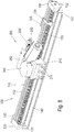
- Fig. 1a shows an electromotive furniture drive in a perspective view.
- the furniture drive is designed as a linear drive with a straight guide track 100, along which an output unit 200 can be moved.
- the guideway 100 is formed in this embodiment substantially by a guide profile 110 which has an approximately rectangular cross-section.
- Fig. 1b and 1c is the electric motor drive the Fig. 1 a shown with cut guide profile 110.
- elements of the output unit 200 are removed ( Fig. 1 b) or shown in section ( Fig. 1 c) to clarify the internal structure of the output unit 200.
- Fig. 2 shows the underside of the electromotive furniture drive in a perspective view.
- the guide profile 110 is preferably an aluminum profile, it may be designed as a plastic profile for certain applications in which no excessive displacement forces applied by the drive or not too large bending forces must be absorbed by the drive. From the sectional view of the guide profile 110 it can be seen that the profile has a groove 111 for receiving a rack 120.
- the groove 111 for receiving a rack 120 is C-shaped, wherein the rack 120 at its toothing opposite side a corresponding complementary Profile, so that the rack 120 can be inserted into the groove 111.
- the rack 120 may be made with a corresponding profile, for example of a hard, durable plastic.
- the rack 120 may be an extruded profile with milled teeth, or may be an injection molded element as a whole.
- the rack 120 may be formed one or more parts. In particular, in a furniture drive with long travels, the production of a correspondingly long one-piece extruded profile can be problematic. In such a case, a multi-part rack 120 offers.
- a guide groove 112 is additionally formed on the side of the guide profile 110 shown in the figure above. Adjacent to the groove 111 for receiving the rack 120, a raceway 113 is provided for an abutment. On the rack 120 opposite side of the track 113 is closed with a parallel to the groove 111 arranged abutment edge 114.
- the function of the anvil will be explained below in connection with the more detailed description of the output unit 200.
- stiffening ribs 115 may be formed within the guide profile 110 within the guide profile 110 within the guide profile 110.
- the mounting flanges 130 provide fasteners 131, here in the form of tapped holes.
- the mounting flanges 130 are connected to the guide profile 110 via bolts 132 or other fastening means.
- the screws 132 may be, for example, self-tapping screws, which are screwed or screwed into suitable chambers or to suitable webs or walls of the guide profile 110.
- suitable chambers or webs are defined, for example, by the reinforcing ribs 115.
- On the mounting flanges 130 also switching cam 133 are arranged, which act together with not visible in this figure and explained below limit switches.
- the output unit 200 has, as a housing part and base element, a slide 210, which is embodied, for example, as an injection molded plastic part in one piece as an approximately C-shaped block which at least partially surrounds the guide profile 110 and runs along the outside of the guide profile 110 in this sense.
- a slide 210 which is embodied, for example, as an injection molded plastic part in one piece as an approximately C-shaped block which at least partially surrounds the guide profile 110 and runs along the outside of the guide profile 110 in this sense.
- the guide groove 112 may be designed as a dovetail groove or as a groove with a T-shaped or with an L-shaped cross section. According to this alternative or additional embodiment of at least one partial region of the guideway 100, the latter thus has a guide profile 110 into which the slider 210 at least partially engages.
- the slider 210 may be designed in several parts, wherein it consists of at least two sections and at least one section is formed as a guide portion for guiding on the guide profile 110, is formed as a fastening portion for attachment via a fastening means 211,212, as a receiving portion for the transmission is formed, or as a storage portion for transmission components such as worm 221, such as drive shaft 230, such as worm gear 231, as output gear 232 is formed.
- the shape of the slider 210 on its surface facing the guide profile 110 is adapted to this accordingly, so that the slider 210 is slidably mounted along the guide profile 110, as far as possible without play or with little play and with respect to all axes.
- fastening means 211 for direct or indirect connection with a furniture part, for example a furniture fitting, are present.
- fastening means 211 of which at least one, for example, the larger central bore is provided with a thread.
- two parallel and opposite the holes projecting edges are provided as further fastening means 212.
- For connection to the furniture or furniture fitting for example, provided with a central bore and two pins plate between the other fastening means 211 are used, wherein the two pins are inserted into the outer holes and the fastening means 211 and in the central threaded bore of the fastening means 211 a Screw is inserted.
- the edges as further fastening means 212 prevent rotation of the inserted plate in addition to the inserted pin.
- a joint which is fastened to the slider 210 with the fixing means 211 or a fixing means 211 having or forming a hinge.
- other fastening means than those shown here for connecting the slider 210 with the furniture or furniture fitting possible.
- a drive motor 220 is fixed to the slider 210.
- a worm 221 is placed on an output shaft of the motor 220.
- a drive shaft 230 is provided with a worm gear 231 engaged with the worm 221 and non-rotatably connected to a driven gear 232 engaged with the rack 120.
- the drive shaft 230 is at least partially hollow, so that at least in the region of the worm gear 231, but preferably also deeper into the drive shaft projecting a bearing receptacle 234 is formed, with the aid of the drive shaft 230 can be stored at least at its upper end in the figure.
- the worm gear 231 and the drive gear 232 may be formed integrally, or else be separate components, which then preferably engage one another positively.
- the drive shaft 230 is hollow over its entire length and is rotatable over its entire length to a Spindle mounted.
- the bearing mandrel is fixed to a gear housing 240, which is screwed onto the slider 210 (see. Fig. 1a . 1c ).
- the bearing mandrel may be formed integrally with the gear housing 240 at this upper side.
- the slider 210 and the gear housing 240 together also form a housing of the output unit. Likewise, they can be considered together as a multi-part gear housing.
- the bearing mandrel projects out of the drive shaft 230.
- the bearing mandrel has at this lower end to a bearing pin 235, for example, in Fig. 1c is visible.
- This journal 235 is mounted in an abutment 236 which runs in the previously described track 213.
- the drive shaft 230 is not formed hollow over its entire length and the bearing pin at the lower end does not protrude from the drive shaft 230.
- the bearing pin may be formed on the drive shaft 230 and the drive shaft 230 may be mounted on this side directly in the anvil 236.
- the abutment 236 is designed as a radial ball bearing.
- this can also be a roller or a displaceable in the raceway 113 Storage block be used. It is also conceivable not to guide the abutment 236 directly in the raceway 113, but to support it in the slide 210, which in turn is supported on the guide profile 110 and / or on the toothed rack 120.
- Fig. 3 is in the upper part of a perpendicular to the longitudinal direction of the guideway 100 executed section shown by the electric motor drive.
- the abutment bearing on the abutment edge 114 of the raceway 112 can again be clearly seen.
- this representation shows how the thread of the screw 132 of the mounting flange 130 cuts into the chamber formed by the reinforcing ribs 115 of the guide profile 110.
- Fig. 4a shows a further perspective and sectional view of the electric motor drive the Fig. 1 , Opposite the representation of the Fig. 1 Here is a view showing the rack 120 of the opposite side.
- the slider 210 is shown cut.
- an electrical connection 250 is arranged, via which the electric motor drive is supplied with power.
- This electrical connection is also in the FIGS. 1a to 1c to recognize. It can be designed as a fixed cable connection or as a plug connection.
- the limit switches 251 may be mechanical switches, such as microswitches in the illustrated embodiment. Alternatively, it is also possible to use optical switches, for example, fork or reflex light barriers in connection with a corresponding control electronics.
- the limit switches 251 are arranged to be actuated by the respective switching cam 133 disposed on the mounting flange 130 at the end of the guide rail 110 when the output unit 200 travels in the end portion of the guide portion 110.
- the limit switches 251 are thus electrically connected to the electrical connection 251 and the drive motor 220, so that further travel of the output unit 200 in the direction of an actuated limit switch 251 is prevented.
- the limit switches 251 are introduced into the supply circuit of the drive motor 220 and open the supply circuit when the respective end region of the guide profile 110 and the guide track 100 are switched.
- Fig. 4b shows the limit switch 251 and acting together with them switching cam 133 once again in an enlarged detail view.
- FIGS. 6a to 6c show a further exemplary embodiment of an electromotive drive.
- Fig. 7 also represents in perspective the guide profile used in this embodiment. Identical reference numerals in these figures denote the same or equivalent elements as in the preceding figures. Concerning. the basic structure of this electromotive furniture drive in the second embodiment is made to the explanation of the first embodiment.
- the guide profile 110 is formed integrally with the rack 120 in this embodiment.
- the mounting flange 130 is formed integrally with the guide profile 110.
- the rack 120 may be formed so that it represents the guide profile 110 itself.
- the guideway 100 is made of plastic in an injection molding process. Unlike the guide profile 110 of the first embodiment, in the present case, no cavities are provided in the profile in order to be able to produce the guide track 100 more easily by injection molding.
- rib structures are arranged in the lower area. These are formed here as longitudinal ribs 116.
- Another difference relates to the track 113 for the abutment 236.
- This track is provided with dust openings 117, through the dust, which falls, for example, furniture cushions on the arranged inside the cabinet electromotive drive, accumulates in the track 113. Ingress of dust into the drive region within the slider 210 is thus prevented or at least reduced, thereby the risk of blocking or increased wear of the drive elements is reduced.
- a cover of the rack 120 may be provided against the falling in and penetration of foreign bodies or dust.
- a gear stage is formed by the worm 221 and the worm wheel 231 for speed reduction between the drive motor 220 and the driven gear 232.
- other types of transmission such as a planetary gear, a spur gear or a friction gear or as a planetary gear possible. It is also possible to use a multi-stage transmission instead of a single one.
- a helical toothing can be used instead of a straight toothing between the output gear and the rack.
- a toothing in the manner of a developed worm wheel is conceivable.
- the toothed rack and toothing is to be understood as meaning any contouring between an element ("rack") extending along the guideway 110 and a rotating output element ("driven gear”).
- the contouring can be done on a microscopic scale, so that a friction wheel drive is conceivable.
- the guideway 100 is straight. However, it is also conceivable to form the guideway 100 at least partially arcuate.
- the guideway 100 may follow the movement of a force introduction point of a furniture component or a moving part of the furniture fitting which is connected to the electromotive drive.
- the guideway 100 is part of the furniture fitting itself.
- the guideway 100 may be a straight or arcuate slide of a furniture fitting provided with a toothing on at least one side.
- slide 210 and rack 120 are guided relative to each other.
- the description of this arrangement can be reduced to explain it, the with the Denture of the rack 120 operatively connected to guide profile 110 for gearbox output driven gear 232 is guided and the guide or the guide profile 110 receives at least the teeth of the rack teeth, so that the rack teeth remains engaged.
- alternative rack profiles are designed in the manner of a rack and pinion.
- alternative gears of the output gear 232 are formed in the manner of a sprocket or in the manner of a Triebstockrades. It is essential, however, that a linear gear acting as a rack gear is thus formed.
- the bearings of the individual gear wheels show.
- the special construction of gear housing 240 and slide 210 allows a particularly simple recording and mounting of the gear members and the thrust bearing 236 and is not limited to the embodiments shown.
- the bearing of the worm 221, the drive shaft 230, the worm gear 231, the driven gear 232 may be partially or fully disposed in the gear housing 240 or at least partially or completely in the slider 210.
- worm 221, drive shaft 230, worm gear 231, driven gear 232 may be partially or fully received by the gear housing 240 and / or partially or entirely by the spool 210.
- the aforementioned bearings and guides are designed as plain bearings and as a sliding guide. Alternatively, however, have at least a portion of the bearings and guides rolling bearings, for example in the form of deep groove ball bearings.
- a shutdown of the drive motor 220 through the limit switch 251 which is formed for example as a micro-switch.
- Another type of shutdown has a reversible switch, which is also arranged in the motor circuit and by a Motorstromschwellwertschalters, for example, a poly-switch component is formed.
- mechanical end stops are arranged, which are formed, for example, as follows: end of the teeth of the rack toothing; Protruding a toothed portion of the rack 120; through the mounting flange 130 which protrudes beyond the limits of the guideway 100 jumping; Fastening screws of the furniture drive in the region of the mounting flange 130. It can also be combined electrical Endabscigenen with mechanical end stops.
- FIG. 8 to 10 a third embodiment of an electric motor drive is shown. Also in these figures, like reference numerals designate the same or equivalent elements as in the preceding figures. Concerning. the basic structure of this electromotive furniture drive in the third embodiment, reference is made to the explanation of the first embodiment.
- the guide profile 110 here has no separate track for the anvil at the lower end of the drive shaft not visible here. Rather, the drive shaft is mounted at its two ends in the transmission housing 210.
- larger toothing forces act through the engagement of the output gear (see FIG Fig. 1 b) in the rack 120, these forces are absorbed by the gear housing 210 and received on the rack 120 opposite side of the guide profile 110.
- Fig. 10 is clearly visible how the gear housing 210 for this purpose, the guide profile 110 surrounds like a clamp. With the above definition, this can also be considered that adjacent to the rack 120, a raceway is provided for an abutment, wherein one side of the guide profile 110 represents the career.
- At least one track is provided which is smooth-surfaced and extends in the longitudinal direction of the guide profile 110.
- a bearing for the drive shaft can in principle be used sliding or ball bearings.
- ball bearings are advantageous in order to minimize friction losses and to be able to use smaller drive motors 220.
- the gear housing 240 does not cover the entire slider 210 in this embodiment, but only the part in which the mechanical Drive elements are located. For the area of the electrical connections 250, a separate connection cover 252 is provided.
- Fig. 8 On the right side arranged switching cam for the limit switch operation. This is not mounted here on the mounting flange, but as a more adjustable switching cam 135 on a displaceable along the guide profile 110 tab 134. In this way, the end position of the slider 210 can be adapted to the respective furniture.
- the rider 134 may be provided with a fixing means, for example, a (maggot) screw to fix it in its desired position.
- the tab 134 is formed with a clamping device or further as a clamp to connect the switching cam 135 with the guide profile 110.
- At least one further tab 134 may be provided, so that a number of tabs 134 with switching cams 135 are provided on the guide profile 110.
- 135 actuate a switch or move a transformer, which actuates a switch.
- the drive unit 200 has at least one switch whose switching contact is integrated in the circuit of the drive motor 220 or, alternatively, when actuated gives a switching signal to a higher-level control.
- a carpet protective rail 140 is disposed below the guide rail 110, which prevents threads of a long-pile carpet between drive gear and rack 110 can pass. Also, grinding marks of the slider 210 at a furniture door arranged very low in the furniture and in a dripping of grease or the like. prevented from the furniture drive.
- the carpet protection rail 140 is preferably clamped or attached to the furniture drive and can thus be easily retrofitted. Alternatively, the carpet protection rail 140 with the electromotive furniture drive connected when this is in the furniture-mounted installation position.
- Both the tab 134 with the adjustable switching cam 135 and the carpet protective rail 140 can also be used in the embodiments shown above.
Landscapes
- Health & Medical Sciences (AREA)
- General Health & Medical Sciences (AREA)
- Nursing (AREA)
- Engineering & Computer Science (AREA)
- General Engineering & Computer Science (AREA)
- Mechanical Engineering (AREA)
- Transmission Devices (AREA)
- Seats For Vehicles (AREA)
- Power-Operated Mechanisms For Wings (AREA)
- Connection Of Motors, Electrical Generators, Mechanical Devices, And The Like (AREA)
Applications Claiming Priority (3)
| Application Number | Priority Date | Filing Date | Title |
|---|---|---|---|
| DE102012107102.0A DE102012107102A1 (de) | 2012-08-02 | 2012-08-02 | Elektromotorischer Möbelantrieb |
| EP13742239.0A EP2879549B1 (fr) | 2012-08-02 | 2013-07-30 | Entraînement électromoteur pour un meuble |
| PCT/EP2013/065991 WO2014020018A1 (fr) | 2012-08-02 | 2013-07-30 | Entraînement électromoteur pour un meuble |
Related Parent Applications (1)
| Application Number | Title | Priority Date | Filing Date |
|---|---|---|---|
| EP13742239.0A Division EP2879549B1 (fr) | 2012-08-02 | 2013-07-30 | Entraînement électromoteur pour un meuble |
Publications (2)
| Publication Number | Publication Date |
|---|---|
| EP3245904A1 true EP3245904A1 (fr) | 2017-11-22 |
| EP3245904B1 EP3245904B1 (fr) | 2020-05-06 |
Family
ID=48877260
Family Applications (2)
| Application Number | Title | Priority Date | Filing Date |
|---|---|---|---|
| EP17181517.8A Active EP3245904B1 (fr) | 2012-08-02 | 2013-07-30 | Entraînement électromoteur pour un meuble |
| EP13742239.0A Active EP2879549B1 (fr) | 2012-08-02 | 2013-07-30 | Entraînement électromoteur pour un meuble |
Family Applications After (1)
| Application Number | Title | Priority Date | Filing Date |
|---|---|---|---|
| EP13742239.0A Active EP2879549B1 (fr) | 2012-08-02 | 2013-07-30 | Entraînement électromoteur pour un meuble |
Country Status (7)
| Country | Link |
|---|---|
| US (1) | US10021991B2 (fr) |
| EP (2) | EP3245904B1 (fr) |
| CN (1) | CN104507363A (fr) |
| DE (1) | DE102012107102A1 (fr) |
| DK (2) | DK2879549T3 (fr) |
| ES (2) | ES2644307T3 (fr) |
| WO (1) | WO2014020018A1 (fr) |
Families Citing this family (27)
| Publication number | Priority date | Publication date | Assignee | Title |
|---|---|---|---|---|
| DE102013110297A1 (de) * | 2013-09-18 | 2015-03-19 | Wolfgang Meyer | Verstelleinheit für Sitz- und Liegemöbel |
| DE102014100444B4 (de) * | 2014-01-16 | 2017-06-29 | MAQUET GmbH | Vorrichtung zum linearen Verschieben einer Patientenlagerfläche und Verfahren zur Montage einer derartigen Vorrichtung |
| DE202015101316U1 (de) | 2015-03-13 | 2016-06-15 | Dewertokin Gmbh | Elektromotorischer Doppelantrieb |
| CN106597832A (zh) * | 2015-10-15 | 2017-04-26 | 江苏爱福特科技开发有限公司 | 一种叫醒装置 |
| US11766956B2 (en) | 2016-09-08 | 2023-09-26 | Fisher & Company, Incorporated | Open architecture power length adjuster assembly for a vehicle seat and method of manufacturing the same |
| DE202016105472U1 (de) | 2016-09-30 | 2018-01-03 | Dewertokin Gmbh | Möbel und elektromotorischer Möbelantrieb mit einer Antriebseinheit und einer Führungsbahn |
| DE202016105473U1 (de) | 2016-09-30 | 2018-01-03 | Dewertokin Gmbh | Möbel und elektromotorischer Möbelantrieb mit einer Antriebseinheit und einer Führungsbahn |
| KR101758288B1 (ko) * | 2017-02-08 | 2017-07-14 | 이기상 | 캐리지 서포트 유닛 및 로봇 캐리지 |
| DE102017204470A1 (de) * | 2017-03-17 | 2018-09-20 | Aktiebolaget Skf | Aktuator und Verfahren zum Abschalten eines Aktuators |
| JP2018193007A (ja) * | 2017-05-19 | 2018-12-06 | トヨタ紡織株式会社 | スライド装置 |
| US10968678B2 (en) * | 2017-07-03 | 2021-04-06 | Hall Labs Llc | Automated sliding panel mechanism with manual release mechanism |
| CN208241502U (zh) * | 2017-09-13 | 2018-12-14 | 嘉兴礼海电气科技有限公司 | 一种提供线性推力的驱动器 |
| JP2019098916A (ja) * | 2017-12-01 | 2019-06-24 | トヨタ紡織株式会社 | スライド装置 |
| CN109878384A (zh) * | 2017-12-01 | 2019-06-14 | 丰田纺织株式会社 | 滑动装置 |
| CN108019478A (zh) * | 2017-12-29 | 2018-05-11 | 温州易得机械科技有限公司 | 一种横向推力装置 |
| CN110495079B (zh) * | 2018-05-15 | 2021-10-29 | 炼马机电(东莞)有限公司 | 一种线性驱动器 |
| DE102018006696A1 (de) * | 2018-08-24 | 2020-02-27 | Goracon Engineering Gmbh | Stuhlführung |
| USD925633S1 (en) * | 2018-12-06 | 2021-07-20 | Logicdata Electronic & Software Entwicklungs Gmbh | Gearbox cover |
| DE112020000364T5 (de) | 2019-01-09 | 2021-10-07 | Fisher & Company, Incorporated | Angetriebene sitzschienenanordnung |
| US11760233B2 (en) * | 2019-02-20 | 2023-09-19 | Fisher & Company, Incorporated | Ultra-compact power length adjuster with anti-back drive capability and pinion-rack output for a vehicle seat |
| US12071044B2 (en) | 2019-03-14 | 2024-08-27 | Magna Seating Inc. | Long rail assembly with internal power driving system |
| TWI803397B (zh) * | 2022-07-21 | 2023-05-21 | 施權航 | 電動床 |
| US12496937B2 (en) | 2022-10-12 | 2025-12-16 | Fisher & Company, Incorporated | Vehicle seat adjustment system with power long rails |
| US12503016B2 (en) | 2022-10-12 | 2025-12-23 | Fisher & Company, Incorporated | Vehicle seat adjustment assembly with reduced-backlash gear system |
| DE102023124025A1 (de) * | 2023-09-06 | 2025-03-06 | Paul Hettich Gmbh & Co. Kg | Führungslager und Möbel- oder Haushaltsgeräteelement |
| EP4603723A1 (fr) * | 2024-02-19 | 2025-08-20 | Emeca | Motoréducteur électrique |
| CN222864006U (zh) * | 2024-08-13 | 2025-05-13 | 常州华达科捷光电仪器有限公司 | 一种激光工具的传动系统 |
Citations (3)
| Publication number | Priority date | Publication date | Assignee | Title |
|---|---|---|---|---|
| US3992956A (en) * | 1973-11-10 | 1976-11-23 | Artur Fischer | Multi-gear transmission for toys |
| JPH0243519U (fr) * | 1988-09-19 | 1990-03-26 | ||
| US5390557A (en) * | 1992-08-11 | 1995-02-21 | Nsk Ltd. | Linear guide system with integrally formed rack |
Family Cites Families (26)
| Publication number | Priority date | Publication date | Assignee | Title |
|---|---|---|---|---|
| JPH0243519A (ja) | 1988-08-03 | 1990-02-14 | Fuji Electric Co Ltd | 表示パネルの組立方法 |
| JPH03121125U (fr) | 1990-03-27 | 1991-12-11 | ||
| US5492414A (en) * | 1995-06-05 | 1996-02-20 | Automation Gages, Inc. | Linear ball slide with rack and pinion |
| US5735214A (en) * | 1996-12-27 | 1998-04-07 | Tsuboi; Nobuyuki | Streamline track system with carriers and rail |
| DE19746208C2 (de) * | 1997-10-20 | 2000-04-06 | Dorma Gmbh & Co Kg | Laufschiene für ein Laufwerk für eine hängend gelagerte Trennwand |
| DE19815283C2 (de) * | 1998-04-06 | 2000-07-13 | Brose Fahrzeugteile | Spindelantrieb für Verstelleinrichtungen in Kraftfahrzeugen |
| DE29811566U1 (de) * | 1998-06-29 | 1998-08-20 | Dewert Antriebs- und Systemtechnik GmbH & Co KG, 32278 Kirchlengern | Elektromotorischer Möbelantrieb |
| DE19920672B4 (de) * | 1999-05-05 | 2006-10-05 | Karlheinz Baumeister | Lineare Stellvorrichtung |
| DE19960940A1 (de) * | 1999-12-17 | 2001-06-21 | Schaeffler Waelzlager Ohg | Linearführungseinheit |
| US6367199B2 (en) * | 2000-02-22 | 2002-04-09 | Delphi Technologies, Inc. | Vehicle liftgate power operating system |
| DE10124316B4 (de) | 2001-05-17 | 2006-05-11 | Karl-Heinz Baumeister | Säule für höhenverstellbare Möbelelemente |
| US6557601B1 (en) * | 2001-08-03 | 2003-05-06 | Taylor Design Group | Mechanical stop system |
| US6764640B1 (en) * | 2001-10-31 | 2004-07-20 | Edison Welding Institute | Torch-based cutting tool |
| JP3950683B2 (ja) * | 2001-12-11 | 2007-08-01 | 日本トムソン株式会社 | 保持器のずれ防止機構を備えた有限直動案内ユニット |
| DE20302142U1 (de) * | 2002-09-16 | 2003-04-24 | Dewert Antriebs- und Systemtechnik GmbH & Co KG, 32278 Kirchlengern | Elektromotorischer Möbelantrieb |
| JP3814270B2 (ja) * | 2003-10-09 | 2006-08-23 | 本田技研工業株式会社 | 車両用自動開閉装置 |
| DE202004018913U1 (de) * | 2004-04-01 | 2005-08-11 | Cimosys Ag | Baukastensystem zur Montage motorisch verstellbarer Stützeinrichtungen für Polsterungen von Sitz- und/oder Liegemöbeln |
| US7686342B2 (en) * | 2005-12-16 | 2010-03-30 | Vetco Gray Inc. | Pipe connector and torque tool |
| US8152492B2 (en) * | 2006-06-12 | 2012-04-10 | Unico, Inc. | Linear rod pump apparatus and method |
| US7611128B2 (en) * | 2006-08-30 | 2009-11-03 | Moteck Electric Corp. | Lifter |
| US7717005B2 (en) * | 2007-04-04 | 2010-05-18 | T-Motion Technology Co., Ltd. | Slide mechanism of linear transmission apparatus |
| US20080262657A1 (en) * | 2007-04-17 | 2008-10-23 | L&P Property Management Company | System and method for controlling adjustable furniture |
| US20100129013A1 (en) * | 2008-11-25 | 2010-05-27 | Pacific Bearing Company | Guide Rail Having Base Rail And Gear Rack, Method Of Making Same, Guide Assembly Including Same |
| US20100126073A1 (en) * | 2008-11-25 | 2010-05-27 | Pacific Bearing Company | Actuator for elevator doors, elevator door arrangement including same and methods |
| JP5414461B2 (ja) * | 2009-10-30 | 2014-02-12 | 株式会社ミツバ | リニアアクチュエータ |
| US8201877B2 (en) | 2010-02-14 | 2012-06-19 | Ping Hsieh | Chair with electrically adjustable components |
-
2012
- 2012-08-02 DE DE102012107102.0A patent/DE102012107102A1/de not_active Withdrawn
-
2013
- 2013-07-30 CN CN201380040751.XA patent/CN104507363A/zh active Pending
- 2013-07-30 US US14/418,836 patent/US10021991B2/en active Active
- 2013-07-30 WO PCT/EP2013/065991 patent/WO2014020018A1/fr not_active Ceased
- 2013-07-30 ES ES13742239.0T patent/ES2644307T3/es active Active
- 2013-07-30 DK DK13742239.0T patent/DK2879549T3/da active
- 2013-07-30 EP EP17181517.8A patent/EP3245904B1/fr active Active
- 2013-07-30 EP EP13742239.0A patent/EP2879549B1/fr active Active
- 2013-07-30 DK DK17181517.8T patent/DK3245904T5/da active
- 2013-07-30 ES ES17181517T patent/ES2805346T3/es active Active
Patent Citations (3)
| Publication number | Priority date | Publication date | Assignee | Title |
|---|---|---|---|---|
| US3992956A (en) * | 1973-11-10 | 1976-11-23 | Artur Fischer | Multi-gear transmission for toys |
| JPH0243519U (fr) * | 1988-09-19 | 1990-03-26 | ||
| US5390557A (en) * | 1992-08-11 | 1995-02-21 | Nsk Ltd. | Linear guide system with integrally formed rack |
Also Published As
| Publication number | Publication date |
|---|---|
| EP2879549B1 (fr) | 2017-07-19 |
| CN104507363A (zh) | 2015-04-08 |
| DK3245904T3 (da) | 2020-08-10 |
| EP2879549A1 (fr) | 2015-06-10 |
| US10021991B2 (en) | 2018-07-17 |
| WO2014020018A1 (fr) | 2014-02-06 |
| EP3245904B1 (fr) | 2020-05-06 |
| ES2805346T3 (es) | 2021-02-11 |
| DE102012107102A1 (de) | 2014-02-06 |
| DK2879549T3 (da) | 2017-11-06 |
| ES2644307T3 (es) | 2017-11-28 |
| US20150289665A1 (en) | 2015-10-15 |
| DK3245904T5 (da) | 2020-08-17 |
Similar Documents
| Publication | Publication Date | Title |
|---|---|---|
| EP2879549B1 (fr) | Entraînement électromoteur pour un meuble | |
| EP2087258B1 (fr) | Entraînement linéaire par moteur électrique | |
| DE68913632T2 (de) | Motorisch verstellbare Sitzgleiteinrichtung. | |
| DE2637438B2 (de) | Elektrischer Fensterantrieb, insbesondere für Kraftfahrzeuge | |
| EP2070447B1 (fr) | Entraînement double de meuble électromotorisé et agencement de commutateur | |
| EP0521251B1 (fr) | Four | |
| EP1100183A2 (fr) | Dispositif d'actionnement à moteur électrique | |
| EP0588812B1 (fr) | Entrainement de broche pour un dispositif de reglage de sieges de vehicules | |
| EP2240050B1 (fr) | Mécanisme d'entraînement double à moteur électrique pour meubles | |
| EP0657123A1 (fr) | Elément de levage plat | |
| WO2005110158A1 (fr) | Entrainement double permettant de regler des parties d'un meuble | |
| EP0918174A2 (fr) | Actionneur linéaire à entraínement motorisé | |
| DE20302142U1 (de) | Elektromotorischer Möbelantrieb | |
| DE102006007068A1 (de) | Linearführungseinrichtung mit Vorspannungseinstelleinrichtung | |
| EP1662159A1 (fr) | Système de guide linéaire avec élément de positionnement | |
| DE19960940A1 (de) | Linearführungseinheit | |
| EP0989006A1 (fr) | Store de fenêtre à commande électromécanique, en particulier pour véhicules automobiles | |
| DE29802535U1 (de) | Elektromotorischer Linearantrieb | |
| DE19920672B4 (de) | Lineare Stellvorrichtung | |
| DE10021898C2 (de) | Vorrichtung zum Verstellen von relativ zueinander beweglichen Teilen | |
| DE20011995U1 (de) | Linearantrieb | |
| DE102005062999B4 (de) | Elektromotorischer Möbelantrieb | |
| EP0374271B1 (fr) | Dispositif de commande d'une porte coulissant horizontalement sur des poulies le long d'un rail de guidage | |
| EP4303387B1 (fr) | Porte ou fenêtre coulissante et relevable avec entraînement | |
| DE4343672A1 (de) | Linearverschiebeeinheit |
Legal Events
| Date | Code | Title | Description |
|---|---|---|---|
| PUAI | Public reference made under article 153(3) epc to a published international application that has entered the european phase |
Free format text: ORIGINAL CODE: 0009012 |
|
| STAA | Information on the status of an ep patent application or granted ep patent |
Free format text: STATUS: THE APPLICATION HAS BEEN PUBLISHED |
|
| AC | Divisional application: reference to earlier application |
Ref document number: 2879549 Country of ref document: EP Kind code of ref document: P |
|
| AK | Designated contracting states |
Kind code of ref document: A1 Designated state(s): AL AT BE BG CH CY CZ DE DK EE ES FI FR GB GR HR HU IE IS IT LI LT LU LV MC MK MT NL NO PL PT RO RS SE SI SK SM TR |
|
| STAA | Information on the status of an ep patent application or granted ep patent |
Free format text: STATUS: REQUEST FOR EXAMINATION WAS MADE |
|
| 17P | Request for examination filed |
Effective date: 20180522 |
|
| RBV | Designated contracting states (corrected) |
Designated state(s): AL AT BE BG CH CY CZ DE DK EE ES FI FR GB GR HR HU IE IS IT LI LT LU LV MC MK MT NL NO PL PT RO RS SE SI SK SM TR |
|
| STAA | Information on the status of an ep patent application or granted ep patent |
Free format text: STATUS: EXAMINATION IS IN PROGRESS |
|
| 17Q | First examination report despatched |
Effective date: 20180823 |
|
| GRAP | Despatch of communication of intention to grant a patent |
Free format text: ORIGINAL CODE: EPIDOSNIGR1 |
|
| STAA | Information on the status of an ep patent application or granted ep patent |
Free format text: STATUS: GRANT OF PATENT IS INTENDED |
|
| INTG | Intention to grant announced |
Effective date: 20191213 |
|
| GRAS | Grant fee paid |
Free format text: ORIGINAL CODE: EPIDOSNIGR3 |
|
| GRAA | (expected) grant |
Free format text: ORIGINAL CODE: 0009210 |
|
| STAA | Information on the status of an ep patent application or granted ep patent |
Free format text: STATUS: THE PATENT HAS BEEN GRANTED |
|
| AC | Divisional application: reference to earlier application |
Ref document number: 2879549 Country of ref document: EP Kind code of ref document: P |
|
| AK | Designated contracting states |
Kind code of ref document: B1 Designated state(s): AL AT BE BG CH CY CZ DE DK EE ES FI FR GB GR HR HU IE IS IT LI LT LU LV MC MK MT NL NO PL PT RO RS SE SI SK SM TR |
|
| REG | Reference to a national code |
Ref country code: GB Ref legal event code: FG4D Free format text: NOT ENGLISH |
|
| REG | Reference to a national code |
Ref country code: CH Ref legal event code: EP Ref country code: AT Ref legal event code: REF Ref document number: 1265414 Country of ref document: AT Kind code of ref document: T Effective date: 20200515 |
|
| REG | Reference to a national code |
Ref country code: IE Ref legal event code: FG4D Free format text: LANGUAGE OF EP DOCUMENT: GERMAN |
|
| REG | Reference to a national code |
Ref country code: DE Ref legal event code: R096 Ref document number: 502013014701 Country of ref document: DE |
|
| REG | Reference to a national code |
Ref country code: DK Ref legal event code: T3 Effective date: 20200803 |
|
| REG | Reference to a national code |
Ref country code: DK Ref legal event code: T5 Effective date: 20200813 |
|
| REG | Reference to a national code |
Ref country code: LT Ref legal event code: MG4D |
|
| REG | Reference to a national code |
Ref country code: NL Ref legal event code: MP Effective date: 20200506 |
|
| PG25 | Lapsed in a contracting state [announced via postgrant information from national office to epo] |
Ref country code: SE Free format text: LAPSE BECAUSE OF FAILURE TO SUBMIT A TRANSLATION OF THE DESCRIPTION OR TO PAY THE FEE WITHIN THE PRESCRIBED TIME-LIMIT Effective date: 20200506 Ref country code: NO Free format text: LAPSE BECAUSE OF FAILURE TO SUBMIT A TRANSLATION OF THE DESCRIPTION OR TO PAY THE FEE WITHIN THE PRESCRIBED TIME-LIMIT Effective date: 20200806 Ref country code: IS Free format text: LAPSE BECAUSE OF FAILURE TO SUBMIT A TRANSLATION OF THE DESCRIPTION OR TO PAY THE FEE WITHIN THE PRESCRIBED TIME-LIMIT Effective date: 20200906 Ref country code: FI Free format text: LAPSE BECAUSE OF FAILURE TO SUBMIT A TRANSLATION OF THE DESCRIPTION OR TO PAY THE FEE WITHIN THE PRESCRIBED TIME-LIMIT Effective date: 20200506 Ref country code: GR Free format text: LAPSE BECAUSE OF FAILURE TO SUBMIT A TRANSLATION OF THE DESCRIPTION OR TO PAY THE FEE WITHIN THE PRESCRIBED TIME-LIMIT Effective date: 20200807 Ref country code: PT Free format text: LAPSE BECAUSE OF FAILURE TO SUBMIT A TRANSLATION OF THE DESCRIPTION OR TO PAY THE FEE WITHIN THE PRESCRIBED TIME-LIMIT Effective date: 20200907 Ref country code: LT Free format text: LAPSE BECAUSE OF FAILURE TO SUBMIT A TRANSLATION OF THE DESCRIPTION OR TO PAY THE FEE WITHIN THE PRESCRIBED TIME-LIMIT Effective date: 20200506 |
|
| PG25 | Lapsed in a contracting state [announced via postgrant information from national office to epo] |
Ref country code: HR Free format text: LAPSE BECAUSE OF FAILURE TO SUBMIT A TRANSLATION OF THE DESCRIPTION OR TO PAY THE FEE WITHIN THE PRESCRIBED TIME-LIMIT Effective date: 20200506 Ref country code: LV Free format text: LAPSE BECAUSE OF FAILURE TO SUBMIT A TRANSLATION OF THE DESCRIPTION OR TO PAY THE FEE WITHIN THE PRESCRIBED TIME-LIMIT Effective date: 20200506 Ref country code: BG Free format text: LAPSE BECAUSE OF FAILURE TO SUBMIT A TRANSLATION OF THE DESCRIPTION OR TO PAY THE FEE WITHIN THE PRESCRIBED TIME-LIMIT Effective date: 20200806 Ref country code: RS Free format text: LAPSE BECAUSE OF FAILURE TO SUBMIT A TRANSLATION OF THE DESCRIPTION OR TO PAY THE FEE WITHIN THE PRESCRIBED TIME-LIMIT Effective date: 20200506 |
|
| PG25 | Lapsed in a contracting state [announced via postgrant information from national office to epo] |
Ref country code: NL Free format text: LAPSE BECAUSE OF FAILURE TO SUBMIT A TRANSLATION OF THE DESCRIPTION OR TO PAY THE FEE WITHIN THE PRESCRIBED TIME-LIMIT Effective date: 20200506 Ref country code: AL Free format text: LAPSE BECAUSE OF FAILURE TO SUBMIT A TRANSLATION OF THE DESCRIPTION OR TO PAY THE FEE WITHIN THE PRESCRIBED TIME-LIMIT Effective date: 20200506 |
|
| PG25 | Lapsed in a contracting state [announced via postgrant information from national office to epo] |
Ref country code: EE Free format text: LAPSE BECAUSE OF FAILURE TO SUBMIT A TRANSLATION OF THE DESCRIPTION OR TO PAY THE FEE WITHIN THE PRESCRIBED TIME-LIMIT Effective date: 20200506 Ref country code: SM Free format text: LAPSE BECAUSE OF FAILURE TO SUBMIT A TRANSLATION OF THE DESCRIPTION OR TO PAY THE FEE WITHIN THE PRESCRIBED TIME-LIMIT Effective date: 20200506 Ref country code: RO Free format text: LAPSE BECAUSE OF FAILURE TO SUBMIT A TRANSLATION OF THE DESCRIPTION OR TO PAY THE FEE WITHIN THE PRESCRIBED TIME-LIMIT Effective date: 20200506 Ref country code: CZ Free format text: LAPSE BECAUSE OF FAILURE TO SUBMIT A TRANSLATION OF THE DESCRIPTION OR TO PAY THE FEE WITHIN THE PRESCRIBED TIME-LIMIT Effective date: 20200506 |
|
| REG | Reference to a national code |
Ref country code: DE Ref legal event code: R097 Ref document number: 502013014701 Country of ref document: DE |
|
| REG | Reference to a national code |
Ref country code: ES Ref legal event code: FG2A Ref document number: 2805346 Country of ref document: ES Kind code of ref document: T3 Effective date: 20210211 |
|
| PG25 | Lapsed in a contracting state [announced via postgrant information from national office to epo] |
Ref country code: PL Free format text: LAPSE BECAUSE OF FAILURE TO SUBMIT A TRANSLATION OF THE DESCRIPTION OR TO PAY THE FEE WITHIN THE PRESCRIBED TIME-LIMIT Effective date: 20200506 Ref country code: SK Free format text: LAPSE BECAUSE OF FAILURE TO SUBMIT A TRANSLATION OF THE DESCRIPTION OR TO PAY THE FEE WITHIN THE PRESCRIBED TIME-LIMIT Effective date: 20200506 Ref country code: MC Free format text: LAPSE BECAUSE OF FAILURE TO SUBMIT A TRANSLATION OF THE DESCRIPTION OR TO PAY THE FEE WITHIN THE PRESCRIBED TIME-LIMIT Effective date: 20200506 |
|
| REG | Reference to a national code |
Ref country code: CH Ref legal event code: PL |
|
| PLBE | No opposition filed within time limit |
Free format text: ORIGINAL CODE: 0009261 |
|
| STAA | Information on the status of an ep patent application or granted ep patent |
Free format text: STATUS: NO OPPOSITION FILED WITHIN TIME LIMIT |
|
| 26N | No opposition filed |
Effective date: 20210209 |
|
| REG | Reference to a national code |
Ref country code: BE Ref legal event code: MM Effective date: 20200731 |
|
| PG25 | Lapsed in a contracting state [announced via postgrant information from national office to epo] |
Ref country code: LI Free format text: LAPSE BECAUSE OF NON-PAYMENT OF DUE FEES Effective date: 20200731 Ref country code: LU Free format text: LAPSE BECAUSE OF NON-PAYMENT OF DUE FEES Effective date: 20200730 Ref country code: CH Free format text: LAPSE BECAUSE OF NON-PAYMENT OF DUE FEES Effective date: 20200731 |
|
| PG25 | Lapsed in a contracting state [announced via postgrant information from national office to epo] |
Ref country code: SI Free format text: LAPSE BECAUSE OF FAILURE TO SUBMIT A TRANSLATION OF THE DESCRIPTION OR TO PAY THE FEE WITHIN THE PRESCRIBED TIME-LIMIT Effective date: 20200506 Ref country code: BE Free format text: LAPSE BECAUSE OF NON-PAYMENT OF DUE FEES Effective date: 20200731 |
|
| PG25 | Lapsed in a contracting state [announced via postgrant information from national office to epo] |
Ref country code: IE Free format text: LAPSE BECAUSE OF NON-PAYMENT OF DUE FEES Effective date: 20200730 |
|
| REG | Reference to a national code |
Ref country code: AT Ref legal event code: MM01 Ref document number: 1265414 Country of ref document: AT Kind code of ref document: T Effective date: 20200730 |
|
| PG25 | Lapsed in a contracting state [announced via postgrant information from national office to epo] |
Ref country code: AT Free format text: LAPSE BECAUSE OF NON-PAYMENT OF DUE FEES Effective date: 20200730 |
|
| REG | Reference to a national code |
Ref country code: GB Ref legal event code: 732E Free format text: REGISTERED BETWEEN 20220127 AND 20220202 |
|
| REG | Reference to a national code |
Ref country code: DE Ref legal event code: R081 Ref document number: 502013014701 Country of ref document: DE Owner name: DEWERTOKIN TECHNOLOGY GROUP CO., LTD., JIAXING, CN Free format text: FORMER OWNER: DEWERTOKIN GMBH, 32278 KIRCHLENGERN, DE |
|
| PG25 | Lapsed in a contracting state [announced via postgrant information from national office to epo] |
Ref country code: TR Free format text: LAPSE BECAUSE OF FAILURE TO SUBMIT A TRANSLATION OF THE DESCRIPTION OR TO PAY THE FEE WITHIN THE PRESCRIBED TIME-LIMIT Effective date: 20200506 Ref country code: MT Free format text: LAPSE BECAUSE OF FAILURE TO SUBMIT A TRANSLATION OF THE DESCRIPTION OR TO PAY THE FEE WITHIN THE PRESCRIBED TIME-LIMIT Effective date: 20200506 Ref country code: CY Free format text: LAPSE BECAUSE OF FAILURE TO SUBMIT A TRANSLATION OF THE DESCRIPTION OR TO PAY THE FEE WITHIN THE PRESCRIBED TIME-LIMIT Effective date: 20200506 |
|
| PG25 | Lapsed in a contracting state [announced via postgrant information from national office to epo] |
Ref country code: MK Free format text: LAPSE BECAUSE OF FAILURE TO SUBMIT A TRANSLATION OF THE DESCRIPTION OR TO PAY THE FEE WITHIN THE PRESCRIBED TIME-LIMIT Effective date: 20200506 |
|
| P01 | Opt-out of the competence of the unified patent court (upc) registered |
Effective date: 20230329 |
|
| PGFP | Annual fee paid to national office [announced via postgrant information from national office to epo] |
Ref country code: DK Payment date: 20250627 Year of fee payment: 13 |
|
| PGFP | Annual fee paid to national office [announced via postgrant information from national office to epo] |
Ref country code: ES Payment date: 20250811 Year of fee payment: 13 |
|
| PGFP | Annual fee paid to national office [announced via postgrant information from national office to epo] |
Ref country code: DE Payment date: 20250711 Year of fee payment: 13 |
|
| PGFP | Annual fee paid to national office [announced via postgrant information from national office to epo] |
Ref country code: IT Payment date: 20250708 Year of fee payment: 13 |
|
| PGFP | Annual fee paid to national office [announced via postgrant information from national office to epo] |
Ref country code: GB Payment date: 20250723 Year of fee payment: 13 |
|
| PGFP | Annual fee paid to national office [announced via postgrant information from national office to epo] |
Ref country code: FR Payment date: 20250730 Year of fee payment: 13 |