EP1100183A2 - Dispositif d'actionnement à moteur électrique - Google Patents
Dispositif d'actionnement à moteur électrique Download PDFInfo
- Publication number
- EP1100183A2 EP1100183A2 EP00123096A EP00123096A EP1100183A2 EP 1100183 A2 EP1100183 A2 EP 1100183A2 EP 00123096 A EP00123096 A EP 00123096A EP 00123096 A EP00123096 A EP 00123096A EP 1100183 A2 EP1100183 A2 EP 1100183A2
- Authority
- EP
- European Patent Office
- Prior art keywords
- adjusting device
- spindle
- electromotive
- drive
- spindles
- Prior art date
- Legal status (The legal status is an assumption and is not a legal conclusion. Google has not performed a legal analysis and makes no representation as to the accuracy of the status listed.)
- Withdrawn
Links
- 238000005516 engineering process Methods 0.000 claims abstract description 3
- 230000000903 blocking effect Effects 0.000 claims description 3
- 238000001514 detection method Methods 0.000 claims description 2
- 238000011156 evaluation Methods 0.000 claims description 2
- 230000003287 optical effect Effects 0.000 claims description 2
- 230000005540 biological transmission Effects 0.000 claims 3
- 238000009434 installation Methods 0.000 abstract description 3
- 238000010276 construction Methods 0.000 description 3
- 230000002093 peripheral effect Effects 0.000 description 2
- 230000008878 coupling Effects 0.000 description 1
- 238000010168 coupling process Methods 0.000 description 1
- 238000005859 coupling reaction Methods 0.000 description 1
- 238000005259 measurement Methods 0.000 description 1
- 238000005096 rolling process Methods 0.000 description 1
Images

Classifications
-
- A—HUMAN NECESSITIES
- A47—FURNITURE; DOMESTIC ARTICLES OR APPLIANCES; COFFEE MILLS; SPICE MILLS; SUCTION CLEANERS IN GENERAL
- A47C—CHAIRS; SOFAS; BEDS
- A47C20/00—Head-, foot- or like rests for beds, sofas or the like
- A47C20/04—Head-, foot- or like rests for beds, sofas or the like with adjustable inclination
- A47C20/041—Head-, foot- or like rests for beds, sofas or the like with adjustable inclination by electric motors
-
- H—ELECTRICITY
- H02—GENERATION; CONVERSION OR DISTRIBUTION OF ELECTRIC POWER
- H02K—DYNAMO-ELECTRIC MACHINES
- H02K7/00—Arrangements for handling mechanical energy structurally associated with dynamo-electric machines, e.g. structural association with mechanical driving motors or auxiliary dynamo-electric machines
- H02K7/06—Means for converting reciprocating motion into rotary motion or vice versa
-
- F—MECHANICAL ENGINEERING; LIGHTING; HEATING; WEAPONS; BLASTING
- F16—ENGINEERING ELEMENTS AND UNITS; GENERAL MEASURES FOR PRODUCING AND MAINTAINING EFFECTIVE FUNCTIONING OF MACHINES OR INSTALLATIONS; THERMAL INSULATION IN GENERAL
- F16H—GEARING
- F16H25/00—Gearings comprising primarily only cams, cam-followers and screw-and-nut mechanisms
- F16H25/18—Gearings comprising primarily only cams, cam-followers and screw-and-nut mechanisms for conveying or interconverting oscillating or reciprocating motions
- F16H25/20—Screw mechanisms
- F16H2025/2053—Screws in parallel arrangement driven simultaneously with an output member moved by the screws
-
- Y—GENERAL TAGGING OF NEW TECHNOLOGICAL DEVELOPMENTS; GENERAL TAGGING OF CROSS-SECTIONAL TECHNOLOGIES SPANNING OVER SEVERAL SECTIONS OF THE IPC; TECHNICAL SUBJECTS COVERED BY FORMER USPC CROSS-REFERENCE ART COLLECTIONS [XRACs] AND DIGESTS
- Y10—TECHNICAL SUBJECTS COVERED BY FORMER USPC
- Y10T—TECHNICAL SUBJECTS COVERED BY FORMER US CLASSIFICATION
- Y10T74/00—Machine element or mechanism
- Y10T74/18—Mechanical movements
- Y10T74/18568—Reciprocating or oscillating to or from alternating rotary
- Y10T74/18576—Reciprocating or oscillating to or from alternating rotary including screw and nut
- Y10T74/18616—Single input, plural outputs
-
- Y—GENERAL TAGGING OF NEW TECHNOLOGICAL DEVELOPMENTS; GENERAL TAGGING OF CROSS-SECTIONAL TECHNOLOGIES SPANNING OVER SEVERAL SECTIONS OF THE IPC; TECHNICAL SUBJECTS COVERED BY FORMER USPC CROSS-REFERENCE ART COLLECTIONS [XRACs] AND DIGESTS
- Y10—TECHNICAL SUBJECTS COVERED BY FORMER USPC
- Y10T—TECHNICAL SUBJECTS COVERED BY FORMER US CLASSIFICATION
- Y10T74/00—Machine element or mechanism
- Y10T74/18—Mechanical movements
- Y10T74/18568—Reciprocating or oscillating to or from alternating rotary
- Y10T74/18576—Reciprocating or oscillating to or from alternating rotary including screw and nut
- Y10T74/18688—Limit stop
-
- Y—GENERAL TAGGING OF NEW TECHNOLOGICAL DEVELOPMENTS; GENERAL TAGGING OF CROSS-SECTIONAL TECHNOLOGIES SPANNING OVER SEVERAL SECTIONS OF THE IPC; TECHNICAL SUBJECTS COVERED BY FORMER USPC CROSS-REFERENCE ART COLLECTIONS [XRACs] AND DIGESTS
- Y10—TECHNICAL SUBJECTS COVERED BY FORMER USPC
- Y10T—TECHNICAL SUBJECTS COVERED BY FORMER US CLASSIFICATION
- Y10T74/00—Machine element or mechanism
- Y10T74/18—Mechanical movements
- Y10T74/18568—Reciprocating or oscillating to or from alternating rotary
- Y10T74/18792—Reciprocating or oscillating to or from alternating rotary including worm
-
- Y—GENERAL TAGGING OF NEW TECHNOLOGICAL DEVELOPMENTS; GENERAL TAGGING OF CROSS-SECTIONAL TECHNOLOGIES SPANNING OVER SEVERAL SECTIONS OF THE IPC; TECHNICAL SUBJECTS COVERED BY FORMER USPC CROSS-REFERENCE ART COLLECTIONS [XRACs] AND DIGESTS
- Y10—TECHNICAL SUBJECTS COVERED BY FORMER USPC
- Y10T—TECHNICAL SUBJECTS COVERED BY FORMER US CLASSIFICATION
- Y10T74/00—Machine element or mechanism
- Y10T74/19—Gearing
- Y10T74/19023—Plural power paths to and/or from gearing
- Y10T74/19074—Single drive plural driven
- Y10T74/19079—Parallel
-
- Y—GENERAL TAGGING OF NEW TECHNOLOGICAL DEVELOPMENTS; GENERAL TAGGING OF CROSS-SECTIONAL TECHNOLOGIES SPANNING OVER SEVERAL SECTIONS OF THE IPC; TECHNICAL SUBJECTS COVERED BY FORMER USPC CROSS-REFERENCE ART COLLECTIONS [XRACs] AND DIGESTS
- Y10—TECHNICAL SUBJECTS COVERED BY FORMER USPC
- Y10T—TECHNICAL SUBJECTS COVERED BY FORMER US CLASSIFICATION
- Y10T74/00—Machine element or mechanism
- Y10T74/19—Gearing
- Y10T74/19642—Directly cooperating gears
- Y10T74/19698—Spiral
- Y10T74/19828—Worm
-
- Y—GENERAL TAGGING OF NEW TECHNOLOGICAL DEVELOPMENTS; GENERAL TAGGING OF CROSS-SECTIONAL TECHNOLOGIES SPANNING OVER SEVERAL SECTIONS OF THE IPC; TECHNICAL SUBJECTS COVERED BY FORMER USPC CROSS-REFERENCE ART COLLECTIONS [XRACs] AND DIGESTS
- Y10—TECHNICAL SUBJECTS COVERED BY FORMER USPC
- Y10T—TECHNICAL SUBJECTS COVERED BY FORMER US CLASSIFICATION
- Y10T74/00—Machine element or mechanism
- Y10T74/19—Gearing
- Y10T74/19642—Directly cooperating gears
- Y10T74/19698—Spiral
- Y10T74/19828—Worm
- Y10T74/19842—Distribution of pressure
Definitions
- the invention relates to an electromotive adjustment device with at least two rotating drivable spindles.
- each is Spindle coupled to a drive gear motor so that the spindles are independent can be driven from each other.
- Such adjustment devices are used, for example, around the head and foot of a slatted frame to adjust.
- the spindles are aligned.
- Each Spindle nut is connected to a lever that, for example, rotates on an axis or shaft of the furniture component to be adjusted is fixed.
- So-called single drives are also known which are equipped with a spindle are on which a spindle nut is placed.
- drives are known at which the gear motor moves on the spindle when it rotates. The speeds the spindles in the aforementioned adjustment devices are relatively small because the drive is located between the drive motor and the threaded spindle Worm drive takes place.
- the invention has for its object an electromotive adjusting device the type described in more detail at the outset so that the adjustment speed one connected to the electromotive adjustment device Component is increased, and that if necessary, the adjustment path opposite the known adjusting devices increased, for example doubled, without that the installation space required is increased or significantly increased.
- the task is solved by the spindles with a single drive motor coupled in terms of drive technology, in parallel and at a distance from each other are arranged.
- the adjustment device according to the invention can explained both spindles are only driven at the same time.
- the linear speed of the output member Adjustment device can be increased significantly as the speeds of the components moved by the spindle add up. It is also possible that with an appropriate design, the adjustment path is increased.
- the inventive Adjustment devices can be used in many ways. So it is possible that it is mounted in a column, for example around the table top of a work table to raise. He could also in the table leg made of a tube of a table.
- the two spindles will then driven in opposite directions, in the event that the worm wheels are identical the speeds match.
- the worm wheels are preferably semi-globoid Gearing.
- the adjustment path and the speed of the component connected to the output element of the adjusting device is compared the known adjustment devices significantly increased when a Worm wheel has an internal thread bore designed as a movement thread, which is engaged with the first spindle and when the other worm wheel is rotatably connected to the second spindle.
- Possibilities for adjustment So it is possible that the first threaded spindle is non-rotatable, so that the worm wheel placed on the first threaded spindle is movable.
- the height of the table top could be adjusted Coupling elements to be connected to the second threaded spindle. Then it should be made sure that that from the worm and the two worm wheels and the drive motor existing gear in a guide of the column or Table leg is guided.
- the worm wheels and the worm gear unit is arranged in a stationary manner, so that the first threaded spindle is linear relative to the associated worm wheel is movable. In such a design, the adjustment speed and to increase the adjustment path, it is then necessary that the adjustment device surrounding tube is telescopic.
- the second becomes normally non-rotatable with the driving worm wheel connected to the spindle to be adjusted Component, for example a table top connected via additional components. It is therefore envisaged that on this second spindle against rotation secured spindle nut is placed, which can only be moved linearly. there it is then expedient if the spindle nut with a retractable and extendable Lift or push tube is connected. In a surrounding the lifting or push tube Flange tube is then used a perforated rail on which to limit the End positions of the spindle nut limit switches are used. The position of the limit switches can be changed so that the full movability is not used must be used if the full path is not used in an application can or should. In the present case, the limit switches determine the stroke for the entire drive. The limit switches can also be arranged at other locations become.
- the spindles with their worm gears assigned end regions arranged on both sides of the worm wheels Bearings are stored. This will make every spindle adequately stored. So that the distance between the first and the second spindle is as small as possible, so that there is an extremely compact design provided that the bearings for supporting each spindle have different diameters and the diagonally opposite bearings have the same Diameter. Those engaged with the driving worm Worm gears are offset from each other by an angle of 180 degrees. In order to Fasteners are accessible, it is provided that perpendicular to the axis of rotation the middle planes of the worm wheels standing offset from one another are.
- each worm wheel to the axis of rotation of the worm is in each case equal. This offset can be achieved constructively in the simplest way if the peripheral toothing of the worm wheels is semi-globoid. In preferred The slopes of the spindles are the same, but they can also differ from one another differ.
- the electromotive adjustment device can be designed such that it is self-locking. If, however, it is to be expected that the adjusting component can cause extremely large forces, the adjustment device could also with a holding brake, for example in the form of at least one wrap spring be equipped. If the electromotive adjustment device is designed in this way is that it is not self-locking in itself, is a suitable brake anyway necessary.
- the end positions of the linearly movable components for example, the spindle nut or the lifting or push tube through limit switches be determined, but it is also possible that the end positions of the linearly movable components of the drive by a mechanical one Blocking device is carried out, preferably by a fixed or adjustable Stop with an electrical switch-off of the drive Measuring device interacts. If the respective linearly movable component against the blocking device moves, the one picked up by the drive motor rises Current. This increase in current can be used as a signal to switch off the drive.
- the end positions can be determined by electrical and / or optical recognition devices are determined, are preferred non-contact buttons or the like used. It is also conceivable that for determination the end positions of the linearly movable components position detection devices are used that are designed so that the drive is switched off when the linearly movable components are in a predetermined position. According to a further embodiment, the revolutions could be rotating drivable components are determined and possibly saved, so that by an evaluation unit is given a signal to switch off the drive when the linearly movable component is in a predetermined position. The linear movable components are in the adjustment devices in question The rotor of the drive motor or the spindle. However, it could also be the revolutions the gear parts of the reduction gear are determined. The best measurement results are achieved, however, when the revolutions of those gear parts can be determined, which are in front of the reduction gear. It is also conceivable that measured the distance covered by the linearly movable components.
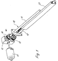
- the electromotive adjusting device 10 shown in FIG. 1 could also be called a linear drive that works like a telescopic drive.
- the Electromotive adjustment device 10 is with a first spindle 11 and second spindle 12, which is parallel and at a distance from the first spindle 11 stands.
- One end of the two spindles 11, 12 is in the retracted state according to FIG. 2 in a housing 13.
- a housing 13 In this housing there is also a gear part in the form of a worm 14 and two drive wheels engaged therewith stored in the form of worm wheels 15, 16.
- the worm 14 is one flanged to the housing 13 driven electric motor 17, the one DC motor is.
- the output pin of the electric motor 17 is shown in the Executed as a screw 14.
- the two worm wheels 15, 16 of identical construction, so that the spindles 11, 12 turn counterclockwise.
- the two spindles 11, 12 are each by two Rolling bearings 18, 19/20, 21 arranged on both sides of the worm wheels 15, 16 are mounted.
- the outer diameter of the two bearings for mounting each spindle 11 or 12 are different, with the diameter as shown in FIG. 2 of the bearing 18 with that of the bearing 20 and the diameter of the bearing 19th coincides with that of the bearing 21.
- the diagonally arranged roller bearings 18/20 respectively 19/21 are identical in construction. This will make the distance between the first Spindle 11 and the second spindle 12 are kept as low as possible so that the electric motor adjustment device is extremely compact.
- the worm wheel 16 assigned to the first spindle has an internally threaded bore Mistake. This thread is a movement thread, so that at Rotation of the worm wheel 16, the first spindle 11 in the illustrated embodiment would move to the left provided the housing 13 is stationary and the spindle 11 is rotatably mounted. As shown in Figure 3, however, the first spindle 11 can mounted so that it cannot turn, i.e. it is not in yours Movable in the longitudinal direction. In this case, the housing 13 would turn to the right move.
- the electric motor 17 is switched on, the worm wheel is also activated 15 driven, whereby the second spindle 12 is also set in rotation becomes.
- a spindle nut 22 is screwed against Rotation is secured so that they move in the longitudinal direction of the second spindle 12 can.
- the spindle nut 22 is connected to a push or lifting tube 23, which can be moved synchronously with the spindle nut 22.
- the push or lifting tube 23 is connected to the part to be adjusted via connecting parts Component, for example a table top coupled.
- Flange tube 27 surrounding push tube or lifting tube 23 is also a perforated rail 24 installed, in which two limit switches 25, 26 are inserted. This will make the two End positions of the spindle nut 22 specified.
- FIG. 4 shows that they are perpendicular to the axis of rotation of the worm wheel 14 Center planes of the worm wheels 15, 16 at the same offset from the axis of rotation of the Worm wheel 14 stand. This creates space, for example To make fasteners accessible.
- the outer peripheral toothing each worm wheel 15, 16 is a semi-globoid toothing.
- the thread shape the spindles can be one of the usual thread types, for example trapezoidal or pointed thread.
- the slopes of the two spindles 11, 12 can be the same or also differ from each other. Depending on the application, the gradients could be the same or opposite.
- the first spindle 11 is not rotatable, so that at Rotation of the worm wheel 16 moves the housing 13 on the first spindle 11.
- the lifting or pushing tube 23 is also extended.
- the speed and the travel distance are greater than in the known ones Drives.
- the adjustment device 10 is installed in a column or leg, it must be ensured that the housing 13 within the column or the Leg is guided so that it can not twist.
- the housing 13 within the column or one leg is fixed in place. In this case the pillar would have to or the leg can be telescoped to increase speed and travel his.
- This adjustment device is that that too transmitted torque distributed to the first spindle 11 and the second spindle 12 , so that either the service life of the spindles can be increased, or that the dimensions can be reduced for a given service life or a poorer quality material can be used.
- the fixed flange tube 27 is attached.
- the invention is not based on the illustrated embodiment is limited.
- the axially parallel is essential Arrangement of the two spindles 11, 12 and these spindles from a single one Electric motor 17 are driven via a reduction gear.
Landscapes
- Engineering & Computer Science (AREA)
- Power Engineering (AREA)
- Health & Medical Sciences (AREA)
- General Health & Medical Sciences (AREA)
- Nursing (AREA)
- Transmission Devices (AREA)
- Gear Transmission (AREA)
- Connection Of Motors, Electrical Generators, Mechanical Devices, And The Like (AREA)
- Motorcycle And Bicycle Frame (AREA)
Applications Claiming Priority (2)
| Application Number | Priority Date | Filing Date | Title |
|---|---|---|---|
| DE29919877U DE29919877U1 (de) | 1999-11-11 | 1999-11-11 | Elektromotorische Verstelleinrichtung |
| DE29919877U | 1999-11-11 |
Publications (2)
| Publication Number | Publication Date |
|---|---|
| EP1100183A2 true EP1100183A2 (fr) | 2001-05-16 |
| EP1100183A3 EP1100183A3 (fr) | 2003-07-02 |
Family
ID=8081517
Family Applications (1)
| Application Number | Title | Priority Date | Filing Date |
|---|---|---|---|
| EP00123096A Withdrawn EP1100183A3 (fr) | 1999-11-11 | 2000-10-25 | Dispositif d'actionnement à moteur électrique |
Country Status (4)
| Country | Link |
|---|---|
| US (1) | US6513398B1 (fr) |
| EP (1) | EP1100183A3 (fr) |
| JP (1) | JP2001182796A (fr) |
| DE (1) | DE29919877U1 (fr) |
Families Citing this family (31)
| Publication number | Priority date | Publication date | Assignee | Title |
|---|---|---|---|---|
| DE4315826C5 (de) * | 1993-05-12 | 2012-04-05 | Continental Teves Ag & Co. Ohg | Motor-Pumpen-Aggregat |
| DE60027380T2 (de) * | 1999-10-07 | 2007-05-10 | ITT Mfg. Enterprises, Inc., Wilmington | Automatische Abschaltvorrichtung |
| DE10254127B4 (de) * | 2002-11-20 | 2014-09-25 | Cimosys Ag | Elektromotorischer Möbelantrieb zum Verstellen von Teilen eines Möbels relativ zueinander |
| DE10254129B4 (de) * | 2002-11-20 | 2014-10-30 | Cimosys Ag | Elektromotorischer Möbelantrieb zum Verstellen von Teilen eines Möbels relativ zueinander |
| DE10254125B4 (de) * | 2002-11-20 | 2014-11-06 | Cimosys Ag | Elektromotorischer Möbelantrieb zum Verstellen von Teilen eines Möbels relativ zueinander |
| US20050122095A1 (en) * | 2003-12-05 | 2005-06-09 | Dooley Kevin A. | Rotation sensor and method |
| US8156839B2 (en) * | 2004-10-26 | 2012-04-17 | Stoneridge Control Devices, Inc. | Vehicle gear box actuator |
| US8006817B2 (en) * | 2005-11-02 | 2011-08-30 | Dura Global Technologies, Llc | Power strut assembly |
| US7802664B2 (en) * | 2005-11-02 | 2010-09-28 | Dura Global Technologies, Llc | Power strut assembly |
| DE102005063000A1 (de) * | 2005-12-30 | 2007-07-12 | Dewert Antriebs- Und Systemtechnik Gmbh | Elektromotorischer Linearantrieb |
| DE102005062999B4 (de) * | 2005-12-30 | 2016-10-27 | Dewertokin Gmbh | Elektromotorischer Möbelantrieb |
| US7712389B2 (en) * | 2006-05-16 | 2010-05-11 | T-Motion Technology Co., Ltd. | Lifting device having parallel double screw rods |
| FR2901587B1 (fr) * | 2006-05-29 | 2009-01-16 | Valeo Embrayages | Actionneur a rattrapage de course, en particulier pour un embrayage de vehicule automobile |
| JP2008019902A (ja) * | 2006-07-11 | 2008-01-31 | Mabuchi Motor Co Ltd | 直動アクチュエータ |
| US9759087B2 (en) | 2007-08-08 | 2017-09-12 | Rohr, Inc. | Translating variable area fan nozzle providing an upstream bypass flow exit |
| EP2479414B1 (fr) | 2007-08-08 | 2015-06-10 | Rohr, Inc. | Tuyère de soufflante à surface variable avec flux de dérivation |
| CN102066808B (zh) | 2008-06-27 | 2013-07-31 | 利纳克有限公司 | 线性致动器 |
| JP5594945B2 (ja) * | 2008-08-06 | 2014-09-24 | 日本トムソン株式会社 | アンプ回路を備えたスライド装置 |
| DE102011018231A1 (de) * | 2011-04-19 | 2012-10-25 | Murrplastik Produktionstechnik Gmbh | Stellvorrichtung |
| US8791663B2 (en) * | 2012-10-19 | 2014-07-29 | Robotzone, Llc | Hobby servo motor linear actuator systems |
| TWI503496B (zh) * | 2013-05-23 | 2015-10-11 | Timotion Technology Co Ltd | 具有位置檢出機構的電動缸 |
| CN103307246B (zh) * | 2013-07-02 | 2015-08-12 | 北京联合大学 | 行程可调推杆机构 |
| DE102014221699A1 (de) * | 2014-10-24 | 2016-04-28 | Suspa Gmbh | Vorrichtung zum Höhenverstellen eines ersten Teils gegenüber einem zweiten Teil, Nachrüstsatz für eine derartige Vorrichtung sowie höhenverstellbares System umfassend mehrere derartige Vorrichtungen |
| DE102015104111A1 (de) * | 2015-03-19 | 2016-09-22 | Witte Automotive Gmbh | Antriebsmechanismus mit Doppelschneckengetriebe |
| WO2017024103A1 (fr) | 2015-08-04 | 2017-02-09 | Kyntec Corporation | Actionneur à ressort mécanique |
| WO2018145707A1 (fr) * | 2017-02-13 | 2018-08-16 | Linak A/S | Actionneur linéaire |
| TWI660133B (zh) * | 2018-06-22 | 2019-05-21 | 和碩聯合科技股份有限公司 | 伸縮調整裝置 |
| CN111974939A (zh) * | 2020-08-25 | 2020-11-24 | 共享智能铸造产业创新中心有限公司 | 升降机构、工作台举升装置及3d打印机 |
| CN112555372A (zh) * | 2020-12-11 | 2021-03-26 | 中国南方电网有限责任公司超高压输电公司百色局 | 双轴传动丝杠 |
| CA3202809A1 (fr) * | 2020-12-21 | 2022-06-30 | Cef Industries, Llc | Dispositif et procede de transmission de charge redondante a double entrainement |
| TWI803397B (zh) * | 2022-07-21 | 2023-05-21 | 施權航 | 電動床 |
Family Cites Families (15)
| Publication number | Priority date | Publication date | Assignee | Title |
|---|---|---|---|---|
| US1030034A (en) * | 1910-11-10 | 1912-06-18 | Carl Theodor Thorssell | Gearing. |
| US1824495A (en) * | 1923-05-31 | 1931-09-22 | Sullivan Machinery Co | Feeding mechanism |
| US1748948A (en) * | 1927-11-04 | 1930-03-04 | Schloemann Ag | Ingot-pushing device |
| JPS61279522A (ja) * | 1985-06-05 | 1986-12-10 | Ichikou Eng Kk | 取出機用昇降装置 |
| JPS643367A (en) * | 1987-06-25 | 1989-01-09 | Asmo Co Ltd | Adjusting structure for backlash of gear |
| JPH03111196A (ja) * | 1989-09-27 | 1991-05-10 | Fanuc Ltd | 産業用ロボットの伸縮軸作動機構 |
| US5319991A (en) * | 1990-07-19 | 1994-06-14 | Pierrat Michel A | Motor coupling with angular compliance |
| US5427337A (en) * | 1993-01-15 | 1995-06-27 | Md, Inc. | Dual drive mechanism and related methods |
| FR2724208B1 (fr) * | 1994-09-07 | 1996-10-18 | Commissariat Energie Atomique | Systeme telescopique |
| JPH08228456A (ja) * | 1994-12-19 | 1996-09-03 | Fuji Electric Co Ltd | 電子式センサを備える電動シリンダ |
| US5673593A (en) * | 1995-12-14 | 1997-10-07 | Joerns Healthcare, Inc. | Overrunning nut for linear actuator |
| FR2745541B1 (fr) * | 1996-02-29 | 1998-05-22 | Valeo Systemes Dessuyage | Motoreducteur, notamment pour l'entrainement de bras d'essuie-glace dans un vehicule automobile |
| US5809833A (en) * | 1996-09-24 | 1998-09-22 | Dana Corporation | Linear actuator |
| DE29701890U1 (de) * | 1997-02-04 | 1997-03-20 | Dewert Antriebs- und Systemtechnik GmbH & Co KG, 32278 Kirchlengern | Linearantrieb |
| US6026970A (en) * | 1999-03-11 | 2000-02-22 | Par Systems, Inc. | Telescoping tube assembly |
-
1999
- 1999-11-11 DE DE29919877U patent/DE29919877U1/de not_active Expired - Lifetime
-
2000
- 2000-10-25 EP EP00123096A patent/EP1100183A3/fr not_active Withdrawn
- 2000-11-03 US US09/705,629 patent/US6513398B1/en not_active Expired - Fee Related
- 2000-11-08 JP JP2000341002A patent/JP2001182796A/ja active Pending
Also Published As
| Publication number | Publication date |
|---|---|
| DE29919877U1 (de) | 2001-03-15 |
| EP1100183A3 (fr) | 2003-07-02 |
| JP2001182796A (ja) | 2001-07-06 |
| US6513398B1 (en) | 2003-02-04 |
Similar Documents
| Publication | Publication Date | Title |
|---|---|---|
| EP1100183A2 (fr) | Dispositif d'actionnement à moteur électrique | |
| EP2146114B1 (fr) | Entraînement à double broche télescopique | |
| EP2879549B1 (fr) | Entraînement électromoteur pour un meuble | |
| EP2087258B1 (fr) | Entraînement linéaire par moteur électrique | |
| DE69307228T2 (de) | Linearantrieb | |
| WO1997030295A1 (fr) | Dispositif pour actionner un frein sur roue d'un vehicule | |
| EP2194018A2 (fr) | Dispositif de levage | |
| EP1097657B1 (fr) | Unité téléscopique d'entraínement | |
| DE19719510A1 (de) | Vorrichtung zur Umwandlung einer Drehbewegung in eine geradlinige Bewegung | |
| EP0019284A1 (fr) | Dispositif de levage avec deux broches filetées télescopiques | |
| EP3661472B1 (fr) | Appareil à tige de traction, compact, réglable rapidement, autobloquant, destiné à être utilisé lors d'interventions chirurgicales | |
| DE19735492A1 (de) | Koaxialtrieb für den Objekttisch eines Mikroskops | |
| EP1584264B1 (fr) | Système d'entrainement réglable en hauteur notamment pour meubles | |
| DE20210187U1 (de) | Elektromotorischer Möbelantrieb | |
| DE60003821T2 (de) | Motorischer Antrieb | |
| EP1403104B1 (fr) | Barre stabilisatrice réglable pour suspension | |
| EP1152167B1 (fr) | Dispositif pour règler la position entre pièces mobiles l'une par rapport à l'autre | |
| DE10222995C1 (de) | Verstellantrieb für Kraftfahrzeugsitzteile | |
| DE4309398C1 (de) | Säulenartige Hub- und Stützvorrichtung | |
| DE10220071C1 (de) | Vorrichtung zur linearen Hubverstellung | |
| DE20210836U1 (de) | Teleskopierbarer Linearantrieb | |
| DE1025228B (de) | Vorrichtung zur Ausfuehrung geradliniger Verstellbewegung | |
| DE19652905C2 (de) | Antrieb für einen Tisch einer an einer Basis befestigten Transport- oder Hubeinrichtung | |
| DE10344302B4 (de) | Elektromotorische Antriebsanordnung | |
| DE19757567C2 (de) | Einrichtung zur Verstellung des Meßtisches an einem Meßmikroskop |
Legal Events
| Date | Code | Title | Description |
|---|---|---|---|
| PUAI | Public reference made under article 153(3) epc to a published international application that has entered the european phase |
Free format text: ORIGINAL CODE: 0009012 |
|
| AK | Designated contracting states |
Kind code of ref document: A2 Designated state(s): AT BE CH CY DE DK ES FI FR GB GR IE IT LI LU MC NL PT SE |
|
| AX | Request for extension of the european patent |
Free format text: AL;LT;LV;MK;RO;SI |
|
| PUAL | Search report despatched |
Free format text: ORIGINAL CODE: 0009013 |
|
| AK | Designated contracting states |
Designated state(s): AT BE CH CY DE DK ES FI FR GB GR IE IT LI LU MC NL PT SE |
|
| AX | Request for extension of the european patent |
Extension state: AL LT LV MK RO SI |
|
| RIC1 | Information provided on ipc code assigned before grant |
Ipc: 7F 16H 25/20 B Ipc: 7H 02K 7/06 A |
|
| 17P | Request for examination filed |
Effective date: 20031205 |
|
| 17Q | First examination report despatched |
Effective date: 20040119 |
|
| AKX | Designation fees paid |
Designated state(s): AT BE CH CY DE DK ES FI FR GB GR IE IT LI LU MC NL PT SE |
|
| STAA | Information on the status of an ep patent application or granted ep patent |
Free format text: STATUS: THE APPLICATION HAS BEEN WITHDRAWN |
|
| 18W | Application withdrawn |
Effective date: 20040728 |