EP3246104B1 - Procede et dispositif de fabrication d'une piece de formage - Google Patents
Procede et dispositif de fabrication d'une piece de formage Download PDFInfo
- Publication number
- EP3246104B1 EP3246104B1 EP16170138.8A EP16170138A EP3246104B1 EP 3246104 B1 EP3246104 B1 EP 3246104B1 EP 16170138 A EP16170138 A EP 16170138A EP 3246104 B1 EP3246104 B1 EP 3246104B1
- Authority
- EP
- European Patent Office
- Prior art keywords
- upsetting
- axial
- circular blank
- forming
- roller
- Prior art date
- Legal status (The legal status is an assumption and is not a legal conclusion. Google has not performed a legal analysis and makes no representation as to the accuracy of the status listed.)
- Active
Links
Images


Classifications
-
- B—PERFORMING OPERATIONS; TRANSPORTING
- B21—MECHANICAL METAL-WORKING WITHOUT ESSENTIALLY REMOVING MATERIAL; PUNCHING METAL
- B21D—WORKING OR PROCESSING OF SHEET METAL OR METAL TUBES, RODS OR PROFILES WITHOUT ESSENTIALLY REMOVING MATERIAL; PUNCHING METAL
- B21D22/00—Shaping without cutting, by stamping, spinning, or deep-drawing
- B21D22/14—Spinning
- B21D22/16—Spinning over shaping mandrels or formers
-
- B—PERFORMING OPERATIONS; TRANSPORTING
- B21—MECHANICAL METAL-WORKING WITHOUT ESSENTIALLY REMOVING MATERIAL; PUNCHING METAL
- B21D—WORKING OR PROCESSING OF SHEET METAL OR METAL TUBES, RODS OR PROFILES WITHOUT ESSENTIALLY REMOVING MATERIAL; PUNCHING METAL
- B21D53/00—Making other particular articles
- B21D53/26—Making other particular articles wheels or the like
- B21D53/28—Making other particular articles wheels or the like gear wheels
-
- B—PERFORMING OPERATIONS; TRANSPORTING
- B21—MECHANICAL METAL-WORKING WITHOUT ESSENTIALLY REMOVING MATERIAL; PUNCHING METAL
- B21H—MAKING PARTICULAR METAL OBJECTS BY ROLLING, e.g. SCREWS, WHEELS, RINGS, BARRELS, BALLS
- B21H1/00—Making articles shaped as bodies of revolution
- B21H1/02—Making articles shaped as bodies of revolution discs; disc wheels
- B21H1/04—Making articles shaped as bodies of revolution discs; disc wheels with rim, e.g. railways wheels or pulleys
Definitions
- the invention relates to a method for producing a forming part from a blank, in which the blank is set in rotation and is radially fed to an outer edge of the blank at least one compression roll, which has a circumferential shaping groove, the outer edge of the blank is compressed to a thickened region, which is formed in accordance with the forming groove of the compression roller to a thickened edge contour, and the radial upsetting to an outer region of the Ronde laterally at least two axial forming rollers are switched on or assist, which cooperate in forming the edge contour, according to the preamble of claim 1.
- the invention relates to an apparatus for producing a Umformteils from a Ronde, with a drive device for rotating driving a Ronde and with at least one compression roller, which is radially deliverable to the Ronde for compressing the outer edge of the Ronde, according to the preamble of claim.
- the lateral support rollers as a kind of lateral abutment, which contributes to the radial formation of the edge bead of the blank.
- the forming rollers can mitausformen a radially inner bottom edge of the edge contour.
- the invention has for its object to provide a method and an apparatus with which a forming part can be processed from a Ronde particularly efficient with thickening of Rondenrandes.
- the inventive method is characterized in that the two axial forming rollers at least in an initial phase of the radial upsetting of the thickened Area are supplied with an axial Front workedsabstand to each other, which is smaller than an axial width of the forming groove of the compression roller, wherein the thickened area is axially back-plunged.
- a basic idea of the invention is, at least in an initial phase of the radial compression of a blank, to relieve the at least one compression roller in that these side flanks of the thickened region are acted upon directly by two axial forming rollers.
- the axial distance of the two opposing forming rollers is adjusted so that it is at least partially smaller than an axial width of the forming groove of the compression roller.
- a particularly good friction reduction can be achieved according to a development of the invention in that the at least two axial forming rollers are switched on or delivered immediately behind and / or in front of the compression roller.
- the paired forming rollers can be arranged only a few cm behind or in front of the compression roller.
- a further advantageous embodiment of the invention is that the two axial forming rollers are adjusted axially to each other during the upsetting.
- the axial forming rollers each have an axis of rotation which is radially directed to the axis of rotation of the blank.
- the axial distance of the two axial forming rollers to each other is a distance which is preferably parallel to the axis of rotation of the Ronde.
- the axes of rotation of the axial forming rollers may also be angled relative to the radial direction, so that back-upsetting is also made possible on obliquely directed flanks of the thickened edge region of the blank.
- an axial distance of the axial forming rollers can be increased to each other, so that a final shaping takes place substantially through the forming groove of the compression roller.
- the forming rollers may have radially projecting shoulders, which serve as a stop or stop edge to form approximately a radial inner or underside of the edge contour.
- the two axial forming rollers are radially adjusted during the upsetting.
- an adaptation to a gradual reduction of the diameter of the tube during upsetting can take place.
- the axial forming rollers are spaced from the thickened region and the thickened region is finally shaped to the edge contour by the at least one compression roller.
- the forming groove is formed in the compression roller according to the edge contour of the blank to be formed.
- a particularly efficient variant of the method according to an embodiment of the invention is that in the same clamping of the blank, an outer edge with the molded-on thickened edge contour is transferred to a spinning tool and a circumferential wall region is formed.
- the blank is clamped between the spinning tool and a counterholder.
- an edge thickening is carried out, in which case the thickened region of the circular blank is subsequently transferred to the spinning lining in the same clamping operation.
- a cylindrical or cup-shaped workpiece with an inner contour can preferably be produced without cutting in accordance with the outer contour of the spinning tool.
- the transfer be carried out by means of at least one compression roller.
- the compression roller has a multiple function. This multifunctional upset roller reduces the number of necessary pressure rollers and tools.
- a keyway or a toothing is formed, which is formed on the spinning chuck. It forms on the peripheral wall of a corresponding inner profile.
- other profiles and contours can be molded.
- a possible compression roller is characterized in that in addition a radially projecting pressure region is provided, which is designed for pressing and / or for pressure-rolling.
- the compression roller can thus fulfill a dual function. It is used for radial compression with radial force application and for transferring the radial edge region of the Ronde axially on the spinning chuck, wherein substantially axial forces are applied.
- the compression roller is thus formed with a pivot bearing which receives both radial and axial forces.
- a preferred embodiment of the compression roller is that the compression area are arranged in an axial center portion and the pressing portion in a lateral edge portion of the roller body.
- the pressing region is radially projecting and has a pressing radius.
- the pressing region it is particularly advantageous for the pressing region to have, in cross-section, a radially projecting nose with a pressing radius and an inlet and / or outlet slope.
- the inlet bevel can in particular be designed so that a folding of the radially directed Ronde section is effected by an axial movement of the compression roller.
- the inventive device for producing a forming part from a blank is characterized in that a compression roller is provided.
- a spinning chuck is provided, on which an outer profiling is formed, on which an edge portion of the blank for forming a Umformteils with inner profiling can be folded.
- the spinning chuck is part of a clamping device, wherein the Ronde is axially clamped between the spinning chuck and a counter-holder. Due to the preceding thickening, sufficient material is available to fill the external profile reliably.
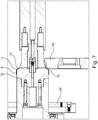
- a rotationally symmetrical blank 1 made of a sheet metal material is clamped axially between a spinning chuck 12 and a counterholder 20.
- the clamped Ronde 1 is set in rotation.
- a compression roller 50 Radially from the outside, a compression roller 50 is delivered with a roller body 52 to an outer edge of the blank 1.
- An upsetting region 54 with a circumferential shaping groove 56 is formed on the roller main body 52 in a middle section. The outer edge of the blank 1 is received in the forming groove 56, which defines an outer contour of the blanking area to be compressed.
- the roller main body 52 is attached to a compression roller shaft 74 which rotatably supported by a radial bearing 76 and a thrust bearing assembly 78 in a holder 80 is.
- a compression roller shaft 74 which rotatably supported by a radial bearing 76 and a thrust bearing assembly 78 in a holder 80 is.
- radial bearings 76 and thrust bearing 78 both forming forces in the radial direction and in the axial direction can be added.
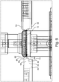
- a first axial forming roller 41 and a second axial forming roller 42 are provided, which are employed axially opposite to the Ronde 1 to be formed.
- the first axial forming roller 41 and the second axial forming roller 42 have an axial forming pitch which is smaller than an axial width of the forming groove 56 of the compression roller 50.
- the two forming rollers 41, 42 are respectively attached to a roller shaft 43 which is rotatable are stored in a first roller holder 45 and a second roller holder 46.
- the first roller holder 45 and the second roller holder 46 are adjustably mounted on a guide support 48. The adjustment can be made via an adjusting device, not shown, in particular adjusting cylinder or a spindle drive.
- the outer edge of the Ronde 1 is compressed.
- the compressed material initially applies to a groove bottom 59 and then to flanks 58 of the molding groove 56.
- the flanks 58 of the forming roller 50 and the adjacent material of the blank 1 to a different direction of movement.
- the two axial forming rollers 41, 42 are axially delivered to the thickening Rondenrand, with a certain axial remindsclaim, for example, about 10% of the wall thickness, the thickened portion of the round blank 1 takes place.
- a friction contact is at least reduced upon re-entry of the thickened area in the compression roller 50.
- the friction wear, a geglageWarende friction heating and a load of the compression roller 50 reduce significantly.
- the axial forming rollers 41, 42 can be further spaced at least to an axial distance corresponding to the width of the shaping groove 56, so that the thickened edge contour 3 on the blank 1 significantly by the contour of the mold groove 56th the compression roller 50 is formed.
- FIGS. 3 and 4 is illustrated that during radial compression an outer diameter of the blank 1 decreases, at the same time a thickened edge contour 3 is formed along the outer edge.
- FIG. 5 A final phase of the shaping of the thickened edge contour 3 with the compression roller 50 and the two axial forming rollers 41, 42, is shown schematically in FIG Fig. 5 shown.
- Fig. 5 It can also be seen that an outer profiling 14 is provided on an outer side of the spinning chuck 12. In the illustrated embodiment, the outer profile 14 is designed as an axial keyway.
- the upset roll 50 according to the invention is provided with the molding groove 56 with an edge-side pressing region 60 in addition to the central swaging region 54.
- a radially projecting nose 62 is provided with a pressure radius, which merges on the one hand in an inlet slope 64 and on the other hand in a discharge slope 66.
- the upset roller 50 according to the invention can also have an opposite end-pressing region 70, with which a front side of the workpiece to be formed can be processed.
- a further flow-forming roller 30 can be delivered to the periphery of the workpiece for folding.
- a frontal profile 16 are formed.
- the compression roller 50 can be delivered to a front side of the Umformmaschines 9 with a forehead-pressing portion 70.
- the only schematically indicated upset roller 50 has in the end-pressing region 70 on a projecting, approximately rectangular pressing edge.
- the forming member 9 Upon completion of the final forming step, the forming member 9 is ejected from the spinning chuck 12 by means of a slidable annular ejector 90 and removed.
- the forming part 9 may be a clutch disk carrier for an automatic transmission. Then, to form another workpiece, a new round blank 1 can be delivered to the device 10 and clamped between the spinning chuck 12 and the counter-holder 20.
Landscapes
- Engineering & Computer Science (AREA)
- Mechanical Engineering (AREA)
- Shaping Metal By Deep-Drawing, Or The Like (AREA)
- Forging (AREA)
Claims (10)
- Procédé pour la fabrication d'une pièce façonnée (9) à partir d'un rond (1), dans lequel :- le rond (1) est amené en rotation et au moins un cylindre de refoulement (50), lequel présente une rainure de formage (56) périphérique, est rapproché radialement d'un bord extérieur du rond (1),- le bord extérieur du rond (1) est refoulé en une zone épaissie, laquelle est formée conformément à la rainure de formage (56) du cylindre de refoulement (50) en un contour de bord (3) épaissi, et- lors du refoulement radial d'une zone extérieure du rond (1), au moins deux cylindres de façonnage (41, 42) axiaux, lesquels agissent conjointement lors du formage du contour de bord (3) opposé, sont placés au niveau de ou sont rapprochés latéralement,caractérisé en ce que- les deux cylindres de façonnage (41, 42) axiaux sont rapprochés l'un de l'autre au moins dans une phase initiale du refoulement radial au niveau de la zone épaissie à une distance de mise en forme axiale, qui est inférieure à une largeur axiale de la rainure de formage (56) du cylindre de refoulement (50), la zone épaissie étant refoulée à l'arrière de manière axiale.
- Procédé selon la revendication 1,
caractérisé en ce que
les au moins deux cylindres de façonnage (41, 42) axiaux sont placés ou rapprochés directement derrière et/ou devant le cylindre de refoulement (50). - Procédé selon la revendication 1 ou 2,
caractérisé en ce que
les deux cylindres de façonnage (41, 42) axiaux sont ajustés de manière axiale l'un par rapport à l'autre pendant le refoulement. - Procédé selon l'une des revendications 1 à 3,
caractérisé en ce que
les deux cylindres de façonnage (41, 42) axiaux sont ajustés de manière radiale pendant le refoulement. - Procédé selon l'une des revendications 1 à 4,
caractérisé en ce que
dans une phase finale du refoulement radial, les cylindres de façonnage (41, 42) axiaux espacés de la zone épaissie et la zone épaissie est formée de manière définitive par l'au moins un cylindre de refoulement (50) en le contour de bord (3). - Procédé selon l'une des revendications 1 à 5,
caractérisé en ce que
lors du même enserrage du rond (1), un bord extérieur avec le contour de bord (3) épaissi formé est replacé sur un mandrin de repoussage (12) et une zone de paroi périphérique (8) est formée. - Procédé selon la revendication 6,
caractérisé en ce que
le replacement est mis en œuvre au moyen de l'au moins un cylindre de refoulement (50). - Procédé selon la revendication 6 ou 7,
caractérisé en ce que
lors du replacement, le contour de bord (3) épaissi est formé dans un profilage extérieur (14), en particulier un profil de rainure de clavette ou une denture, qui est réalisé au niveau du mandrin de repoussage (12). - Dispositif pour la fabrication d'une partie façonnée à partir d'un rond (1) selon un procédé selon l'une des revendications 1 à 8,
avec un système d'entraînement servant à entraîner en rotation un rond (1) et avec au moins un cylindre de refoulement (50) avec une rainure de formage (56), laquelle peut être rapprochée radialement du rond (1) pour refouler le bord extérieur du rond (1) en une zone épaissie, et
avec au moins deux cylindres de façonnage (41, 42) axiaux, lesquels peuvent être rapprochés latéralement du rond (1),
caractérisé en ce que
les deux cylindres de façonnage (41, 42) axiaux sont disposés de telle manière par rapport au cylindre de refoulement (50) que lors du refoulement, les deux cylindres de façonnage (41, 42) axiaux sont rapprochés l'un de l'autre au niveau de la zone épaissie du rond (1) à une distance de mise en forme axiale, laquelle est inférieure à une largeur axiale de la rainure de formage (56) du cylindre de refoulement (50). - Dispositif selon la revendication 9,
caractérisé en ce que
pour enserrer le rond (1), un mandrin de repoussage (12) est prévu, au niveau duquel un profilage extérieur (14) est réalisé, sur lequel une section de bord du rond (1) peut être replacée pour obtenir une partie façonnée (9) avec un profilage intérieur.
Priority Applications (5)
| Application Number | Priority Date | Filing Date | Title |
|---|---|---|---|
| EP16170138.8A EP3246104B1 (fr) | 2016-05-18 | 2016-05-18 | Procede et dispositif de fabrication d'une piece de formage |
| JP2018559951A JP6768837B2 (ja) | 2016-05-18 | 2017-03-27 | 成形部品を製造する方法および装置 |
| US16/301,683 US20190291159A1 (en) | 2016-05-18 | 2017-03-27 | Method and device for producing a formed part |
| PCT/EP2017/057188 WO2017198382A1 (fr) | 2016-05-18 | 2017-03-27 | Procédé et dispositif pour la fabrication d'une pièce déformée |
| CN201780037896.2A CN109475913B (zh) | 2016-05-18 | 2017-03-27 | 用于制造变形件的方法和装置 |
Applications Claiming Priority (1)
| Application Number | Priority Date | Filing Date | Title |
|---|---|---|---|
| EP16170138.8A EP3246104B1 (fr) | 2016-05-18 | 2016-05-18 | Procede et dispositif de fabrication d'une piece de formage |
Publications (2)
| Publication Number | Publication Date |
|---|---|
| EP3246104A1 EP3246104A1 (fr) | 2017-11-22 |
| EP3246104B1 true EP3246104B1 (fr) | 2019-11-06 |
Family
ID=56117478
Family Applications (1)
| Application Number | Title | Priority Date | Filing Date |
|---|---|---|---|
| EP16170138.8A Active EP3246104B1 (fr) | 2016-05-18 | 2016-05-18 | Procede et dispositif de fabrication d'une piece de formage |
Country Status (5)
| Country | Link |
|---|---|
| US (1) | US20190291159A1 (fr) |
| EP (1) | EP3246104B1 (fr) |
| JP (1) | JP6768837B2 (fr) |
| CN (1) | CN109475913B (fr) |
| WO (1) | WO2017198382A1 (fr) |
Families Citing this family (3)
| Publication number | Priority date | Publication date | Assignee | Title |
|---|---|---|---|---|
| CN110125251B (zh) * | 2019-05-16 | 2023-11-14 | 中信戴卡股份有限公司 | 一种车轮旋压模具及脱模装置 |
| CN111151607A (zh) * | 2020-01-15 | 2020-05-15 | 山东金麒麟股份有限公司 | 一种洗衣机制动带整形工装及整形方法 |
| CN112916726A (zh) * | 2020-12-28 | 2021-06-08 | 无锡仓佑汽车配件有限公司 | 一种自动变速箱离合器齿毂内外花键制备工艺 |
Family Cites Families (18)
| Publication number | Priority date | Publication date | Assignee | Title |
|---|---|---|---|---|
| ES2046368T3 (es) * | 1989-05-17 | 1994-02-01 | Leifeld Gmbh & Co. | Procedimiento para la fabricacion de una polea. |
| DE4314558A1 (de) * | 1993-05-04 | 1994-11-17 | Leifeld Gmbh & Co | Verfahren zum spanlosen Herstellen eines Außenprofils an einem hohlzylindrischen Körper und zugehörige Vorrichtung |
| US5531024A (en) * | 1994-03-31 | 1996-07-02 | Motor Wheel Corp | Method of making a full face wheel |
| JP2700717B2 (ja) * | 1995-01-27 | 1998-01-21 | 株式会社カネミツ | 板金製ポリv溝プーリの製造方法及び板金製ポリv溝プーリ |
| US7047781B1 (en) | 1995-01-27 | 2006-05-23 | Kabushiki Kaisha Kanemitsu | Sheet metal member having an annular peripheral wall and a method of thickening an annular peripheral wall of the sheet metal member |
| JPH0966330A (ja) * | 1995-08-31 | 1997-03-11 | Fuji Kiko Co Ltd | 円板外周部の増肉方法及び外周に伝導部を有する円板部材の成形方法 |
| DE19602298C2 (de) * | 1996-01-23 | 1999-11-11 | Leifeld Gmbh & Co | Verfahren zur Herstellung eines rotationssymmetrischen Teiles |
| DE19635152A1 (de) * | 1996-08-14 | 1998-03-12 | Wf Maschinenbau Blechformtech | Verfahren und Vorrichtung zur Herstellung eines außen verzahnten Getriebeteiles |
| WO1998006521A1 (fr) * | 1996-08-14 | 1998-02-19 | Wf-Maschinenbau Und Blechformtechnik Gmbh & Co. Kommanditgesellschaft | Procede et dispositif de fabrication d'une partie d'engrenage a denture exterieure |
| JP3567632B2 (ja) * | 1996-08-19 | 2004-09-22 | マツダ株式会社 | 円筒部品の成形方法 |
| US5878493A (en) | 1996-08-28 | 1999-03-09 | Tesma International Inc. | Method of forming toothed wheels |
| US6196039B1 (en) * | 1999-03-25 | 2001-03-06 | Anvil International, Inc. | Groove rolling of piping elements |
| JP3997684B2 (ja) * | 2000-03-29 | 2007-10-24 | アイシン・エィ・ダブリュ株式会社 | 内歯部材の製造方法 |
| DE10211135B4 (de) | 2002-03-14 | 2008-06-26 | Wf-Maschinenbau Und Blechformtechnik Gmbh & Co Kg | Verfahren und Vorrichtung zur Herstellung eines Formkörpers |
| CN100493757C (zh) * | 2007-10-30 | 2009-06-03 | 华南理工大学 | 一种带轮旋压成形方法及设备 |
| CA2877173C (fr) * | 2012-07-05 | 2020-08-25 | Magna Powertrain Of America, Inc. | Formation de cannelures helicoidales |
| CN103464559A (zh) * | 2013-09-16 | 2013-12-25 | 薛克敏 | 一种薄底厚外缘的盘类零件的成形方法 |
| JP6291230B2 (ja) * | 2013-11-29 | 2018-03-14 | 川崎重工業株式会社 | スピニング成形装置およびスピニング成形方法 |
-
2016
- 2016-05-18 EP EP16170138.8A patent/EP3246104B1/fr active Active
-
2017
- 2017-03-27 US US16/301,683 patent/US20190291159A1/en not_active Abandoned
- 2017-03-27 WO PCT/EP2017/057188 patent/WO2017198382A1/fr not_active Ceased
- 2017-03-27 CN CN201780037896.2A patent/CN109475913B/zh active Active
- 2017-03-27 JP JP2018559951A patent/JP6768837B2/ja active Active
Non-Patent Citations (1)
| Title |
|---|
| None * |
Also Published As
| Publication number | Publication date |
|---|---|
| JP2019514698A (ja) | 2019-06-06 |
| CN109475913A (zh) | 2019-03-15 |
| JP6768837B2 (ja) | 2020-10-14 |
| WO2017198382A1 (fr) | 2017-11-23 |
| CN109475913B (zh) | 2020-08-07 |
| EP3246104A1 (fr) | 2017-11-22 |
| US20190291159A1 (en) | 2019-09-26 |
Similar Documents
| Publication | Publication Date | Title |
|---|---|---|
| DE69830133T2 (de) | Verfahren zur Herstellung eines Getrieberades | |
| EP2127777B1 (fr) | Dispositif et procédé de fabrication ou de traitement de pièces à usiner à partir d'une ébauche, en particulier pour former des profils internes ou des dentures intérieures | |
| EP1108483B1 (fr) | Procédé et dispositif pour le fluotournage | |
| DE19861391B4 (de) | Verfahren zum Formen einer Nabenscheibe und Drückrolle zur Verwendung beim Formen einer Nabenscheibe | |
| WO2016082969A1 (fr) | Procédé de fabrication d'un arbre creux profilé pour un arbre de direction télescopique et arbre de direction télescopique | |
| EP1253984B1 (fr) | Procede et dispositif d'emboutissage pour fabriquer un corps creux | |
| EP0955110B1 (fr) | Procédé et dispositif pour le fluotournage | |
| EP1356891B1 (fr) | Procédé de fabrication de manchons coulissants pour boítes de vitesses | |
| EP4100186B1 (fr) | Outil de laminage et procédé de laminage d'un profilé | |
| DE10039706B4 (de) | Verfahren zum Einbringen einer Sicke und Drückwalzmaschine | |
| WO2017198382A1 (fr) | Procédé et dispositif pour la fabrication d'une pièce déformée | |
| DE19854481C2 (de) | Verfahren und Vorrichtung zum Drückwalzen | |
| EP2167254B1 (fr) | Procédé de fabrication d'un moyeu selon un procédé d'emboutissage au moyen d'au moins un cylindre d'emboutissage rotatif | |
| DE19915027A1 (de) | Getriebeteil und Verfahren zum Formen eines Getriebeteils | |
| EP3278894A1 (fr) | Machine destinee a retreindre et procede de deformation pour la fabrication d'une roue | |
| DE19849981C2 (de) | Verfahren zum Formen eines scheibenförmigen Teiles mit Nabe und Drückrolle für das Verfahren | |
| EP0808678A1 (fr) | Méthode et dispositif pour le fabrication d'une poulie à gorges multiples | |
| EP0997210B1 (fr) | Procédé de fabrication d'objets en forme de disque avec moyeu et rouleau de pression pour exécuter ledit procédé | |
| EP3023171B1 (fr) | Fluotournage de bagues de palier | |
| DE102010011809B4 (de) | Verfahren und Drückwalz- und Profiliermaschine zum Herstellen eines rotationssymmetrischen Werkstückes sowie Profilrolle hierfür | |
| EP1425120B1 (fr) | Dispositif et methode de production d'un corps moule pourvu d'un moyeu concentrique | |
| DE10121546A1 (de) | Verfahren und Drückrolle zum Anformen einer Nabe | |
| DE19632279C2 (de) | Verfahren zur Herstellung eines scheibenförmigen Teiles | |
| EP1362652B1 (fr) | Méthode et dispositif de fluotournage pour le formage d' un moyeu sans enlèvement de copeaux | |
| DE19946508C2 (de) | Verfahren zum Herstellen einer Welle mit durchmessergrößerem Flansch |
Legal Events
| Date | Code | Title | Description |
|---|---|---|---|
| PUAI | Public reference made under article 153(3) epc to a published international application that has entered the european phase |
Free format text: ORIGINAL CODE: 0009012 |
|
| STAA | Information on the status of an ep patent application or granted ep patent |
Free format text: STATUS: REQUEST FOR EXAMINATION WAS MADE |
|
| 17P | Request for examination filed |
Effective date: 20170316 |
|
| AK | Designated contracting states |
Kind code of ref document: A1 Designated state(s): AL AT BE BG CH CY CZ DE DK EE ES FI FR GB GR HR HU IE IS IT LI LT LU LV MC MK MT NL NO PL PT RO RS SE SI SK SM TR |
|
| AX | Request for extension of the european patent |
Extension state: BA ME |
|
| GRAP | Despatch of communication of intention to grant a patent |
Free format text: ORIGINAL CODE: EPIDOSNIGR1 |
|
| STAA | Information on the status of an ep patent application or granted ep patent |
Free format text: STATUS: GRANT OF PATENT IS INTENDED |
|
| INTG | Intention to grant announced |
Effective date: 20190614 |
|
| GRAS | Grant fee paid |
Free format text: ORIGINAL CODE: EPIDOSNIGR3 |
|
| GRAA | (expected) grant |
Free format text: ORIGINAL CODE: 0009210 |
|
| STAA | Information on the status of an ep patent application or granted ep patent |
Free format text: STATUS: THE PATENT HAS BEEN GRANTED |
|
| AK | Designated contracting states |
Kind code of ref document: B1 Designated state(s): AL AT BE BG CH CY CZ DE DK EE ES FI FR GB GR HR HU IE IS IT LI LT LU LV MC MK MT NL NO PL PT RO RS SE SI SK SM TR |
|
| REG | Reference to a national code |
Ref country code: GB Ref legal event code: FG4D Free format text: NOT ENGLISH |
|
| REG | Reference to a national code |
Ref country code: CH Ref legal event code: EP Ref country code: CH Ref legal event code: NV Representative=s name: BOGENSBERGER PATENT- AND MARKENBUERO DR. BURKH, LI Ref country code: AT Ref legal event code: REF Ref document number: 1198061 Country of ref document: AT Kind code of ref document: T Effective date: 20191115 |
|
| REG | Reference to a national code |
Ref country code: DE Ref legal event code: R096 Ref document number: 502016007389 Country of ref document: DE |
|
| REG | Reference to a national code |
Ref country code: IE Ref legal event code: FG4D Free format text: LANGUAGE OF EP DOCUMENT: GERMAN |
|
| REG | Reference to a national code |
Ref country code: NL Ref legal event code: MP Effective date: 20191106 |
|
| REG | Reference to a national code |
Ref country code: LT Ref legal event code: MG4D |
|
| PG25 | Lapsed in a contracting state [announced via postgrant information from national office to epo] |
Ref country code: BG Free format text: LAPSE BECAUSE OF FAILURE TO SUBMIT A TRANSLATION OF THE DESCRIPTION OR TO PAY THE FEE WITHIN THE PRESCRIBED TIME-LIMIT Effective date: 20200206 Ref country code: FI Free format text: LAPSE BECAUSE OF FAILURE TO SUBMIT A TRANSLATION OF THE DESCRIPTION OR TO PAY THE FEE WITHIN THE PRESCRIBED TIME-LIMIT Effective date: 20191106 Ref country code: NO Free format text: LAPSE BECAUSE OF FAILURE TO SUBMIT A TRANSLATION OF THE DESCRIPTION OR TO PAY THE FEE WITHIN THE PRESCRIBED TIME-LIMIT Effective date: 20200206 Ref country code: SE Free format text: LAPSE BECAUSE OF FAILURE TO SUBMIT A TRANSLATION OF THE DESCRIPTION OR TO PAY THE FEE WITHIN THE PRESCRIBED TIME-LIMIT Effective date: 20191106 Ref country code: PT Free format text: LAPSE BECAUSE OF FAILURE TO SUBMIT A TRANSLATION OF THE DESCRIPTION OR TO PAY THE FEE WITHIN THE PRESCRIBED TIME-LIMIT Effective date: 20200306 Ref country code: LV Free format text: LAPSE BECAUSE OF FAILURE TO SUBMIT A TRANSLATION OF THE DESCRIPTION OR TO PAY THE FEE WITHIN THE PRESCRIBED TIME-LIMIT Effective date: 20191106 Ref country code: LT Free format text: LAPSE BECAUSE OF FAILURE TO SUBMIT A TRANSLATION OF THE DESCRIPTION OR TO PAY THE FEE WITHIN THE PRESCRIBED TIME-LIMIT Effective date: 20191106 Ref country code: PL Free format text: LAPSE BECAUSE OF FAILURE TO SUBMIT A TRANSLATION OF THE DESCRIPTION OR TO PAY THE FEE WITHIN THE PRESCRIBED TIME-LIMIT Effective date: 20191106 Ref country code: GR Free format text: LAPSE BECAUSE OF FAILURE TO SUBMIT A TRANSLATION OF THE DESCRIPTION OR TO PAY THE FEE WITHIN THE PRESCRIBED TIME-LIMIT Effective date: 20200207 Ref country code: NL Free format text: LAPSE BECAUSE OF FAILURE TO SUBMIT A TRANSLATION OF THE DESCRIPTION OR TO PAY THE FEE WITHIN THE PRESCRIBED TIME-LIMIT Effective date: 20191106 |
|
| PG25 | Lapsed in a contracting state [announced via postgrant information from national office to epo] |
Ref country code: IS Free format text: LAPSE BECAUSE OF FAILURE TO SUBMIT A TRANSLATION OF THE DESCRIPTION OR TO PAY THE FEE WITHIN THE PRESCRIBED TIME-LIMIT Effective date: 20200306 Ref country code: HR Free format text: LAPSE BECAUSE OF FAILURE TO SUBMIT A TRANSLATION OF THE DESCRIPTION OR TO PAY THE FEE WITHIN THE PRESCRIBED TIME-LIMIT Effective date: 20191106 Ref country code: RS Free format text: LAPSE BECAUSE OF FAILURE TO SUBMIT A TRANSLATION OF THE DESCRIPTION OR TO PAY THE FEE WITHIN THE PRESCRIBED TIME-LIMIT Effective date: 20191106 |
|
| PG25 | Lapsed in a contracting state [announced via postgrant information from national office to epo] |
Ref country code: AL Free format text: LAPSE BECAUSE OF FAILURE TO SUBMIT A TRANSLATION OF THE DESCRIPTION OR TO PAY THE FEE WITHIN THE PRESCRIBED TIME-LIMIT Effective date: 20191106 |
|
| PG25 | Lapsed in a contracting state [announced via postgrant information from national office to epo] |
Ref country code: RO Free format text: LAPSE BECAUSE OF FAILURE TO SUBMIT A TRANSLATION OF THE DESCRIPTION OR TO PAY THE FEE WITHIN THE PRESCRIBED TIME-LIMIT Effective date: 20191106 Ref country code: DK Free format text: LAPSE BECAUSE OF FAILURE TO SUBMIT A TRANSLATION OF THE DESCRIPTION OR TO PAY THE FEE WITHIN THE PRESCRIBED TIME-LIMIT Effective date: 20191106 Ref country code: EE Free format text: LAPSE BECAUSE OF FAILURE TO SUBMIT A TRANSLATION OF THE DESCRIPTION OR TO PAY THE FEE WITHIN THE PRESCRIBED TIME-LIMIT Effective date: 20191106 Ref country code: CZ Free format text: LAPSE BECAUSE OF FAILURE TO SUBMIT A TRANSLATION OF THE DESCRIPTION OR TO PAY THE FEE WITHIN THE PRESCRIBED TIME-LIMIT Effective date: 20191106 Ref country code: ES Free format text: LAPSE BECAUSE OF FAILURE TO SUBMIT A TRANSLATION OF THE DESCRIPTION OR TO PAY THE FEE WITHIN THE PRESCRIBED TIME-LIMIT Effective date: 20191106 |
|
| PGFP | Annual fee paid to national office [announced via postgrant information from national office to epo] |
Ref country code: CH Payment date: 20200522 Year of fee payment: 5 |
|
| REG | Reference to a national code |
Ref country code: DE Ref legal event code: R097 Ref document number: 502016007389 Country of ref document: DE |
|
| PG25 | Lapsed in a contracting state [announced via postgrant information from national office to epo] |
Ref country code: SM Free format text: LAPSE BECAUSE OF FAILURE TO SUBMIT A TRANSLATION OF THE DESCRIPTION OR TO PAY THE FEE WITHIN THE PRESCRIBED TIME-LIMIT Effective date: 20191106 Ref country code: SK Free format text: LAPSE BECAUSE OF FAILURE TO SUBMIT A TRANSLATION OF THE DESCRIPTION OR TO PAY THE FEE WITHIN THE PRESCRIBED TIME-LIMIT Effective date: 20191106 |
|
| PLBE | No opposition filed within time limit |
Free format text: ORIGINAL CODE: 0009261 |
|
| STAA | Information on the status of an ep patent application or granted ep patent |
Free format text: STATUS: NO OPPOSITION FILED WITHIN TIME LIMIT |
|
| 26N | No opposition filed |
Effective date: 20200807 |
|
| PG25 | Lapsed in a contracting state [announced via postgrant information from national office to epo] |
Ref country code: SI Free format text: LAPSE BECAUSE OF FAILURE TO SUBMIT A TRANSLATION OF THE DESCRIPTION OR TO PAY THE FEE WITHIN THE PRESCRIBED TIME-LIMIT Effective date: 20191106 |
|
| PG25 | Lapsed in a contracting state [announced via postgrant information from national office to epo] |
Ref country code: MC Free format text: LAPSE BECAUSE OF FAILURE TO SUBMIT A TRANSLATION OF THE DESCRIPTION OR TO PAY THE FEE WITHIN THE PRESCRIBED TIME-LIMIT Effective date: 20191106 Ref country code: IT Free format text: LAPSE BECAUSE OF FAILURE TO SUBMIT A TRANSLATION OF THE DESCRIPTION OR TO PAY THE FEE WITHIN THE PRESCRIBED TIME-LIMIT Effective date: 20191106 |
|
| REG | Reference to a national code |
Ref country code: BE Ref legal event code: MM Effective date: 20200531 |
|
| GBPC | Gb: european patent ceased through non-payment of renewal fee |
Effective date: 20200518 |
|
| PG25 | Lapsed in a contracting state [announced via postgrant information from national office to epo] |
Ref country code: LU Free format text: LAPSE BECAUSE OF NON-PAYMENT OF DUE FEES Effective date: 20200518 |
|
| REG | Reference to a national code |
Ref country code: DE Ref legal event code: R082 Ref document number: 502016007389 Country of ref document: DE Representative=s name: WUNDERLICH & HEIM PATENTANWAELTE PARTNERSCHAFT, DE Ref country code: DE Ref legal event code: R081 Ref document number: 502016007389 Country of ref document: DE Owner name: LEIFELD METAL SPINNING GMBH, DE Free format text: FORMER OWNER: LEIFELD METAL SPINNING AG, 59229 AHLEN, DE |
|
| PG25 | Lapsed in a contracting state [announced via postgrant information from national office to epo] |
Ref country code: IE Free format text: LAPSE BECAUSE OF NON-PAYMENT OF DUE FEES Effective date: 20200518 Ref country code: GB Free format text: LAPSE BECAUSE OF NON-PAYMENT OF DUE FEES Effective date: 20200518 Ref country code: FR Free format text: LAPSE BECAUSE OF NON-PAYMENT OF DUE FEES Effective date: 20200531 |
|
| PG25 | Lapsed in a contracting state [announced via postgrant information from national office to epo] |
Ref country code: BE Free format text: LAPSE BECAUSE OF NON-PAYMENT OF DUE FEES Effective date: 20200531 |
|
| REG | Reference to a national code |
Ref country code: CH Ref legal event code: PL |
|
| PG25 | Lapsed in a contracting state [announced via postgrant information from national office to epo] |
Ref country code: LI Free format text: LAPSE BECAUSE OF NON-PAYMENT OF DUE FEES Effective date: 20210531 Ref country code: CH Free format text: LAPSE BECAUSE OF NON-PAYMENT OF DUE FEES Effective date: 20210531 |
|
| PG25 | Lapsed in a contracting state [announced via postgrant information from national office to epo] |
Ref country code: TR Free format text: LAPSE BECAUSE OF FAILURE TO SUBMIT A TRANSLATION OF THE DESCRIPTION OR TO PAY THE FEE WITHIN THE PRESCRIBED TIME-LIMIT Effective date: 20191106 Ref country code: MT Free format text: LAPSE BECAUSE OF FAILURE TO SUBMIT A TRANSLATION OF THE DESCRIPTION OR TO PAY THE FEE WITHIN THE PRESCRIBED TIME-LIMIT Effective date: 20191106 Ref country code: CY Free format text: LAPSE BECAUSE OF FAILURE TO SUBMIT A TRANSLATION OF THE DESCRIPTION OR TO PAY THE FEE WITHIN THE PRESCRIBED TIME-LIMIT Effective date: 20191106 |
|
| PG25 | Lapsed in a contracting state [announced via postgrant information from national office to epo] |
Ref country code: MK Free format text: LAPSE BECAUSE OF FAILURE TO SUBMIT A TRANSLATION OF THE DESCRIPTION OR TO PAY THE FEE WITHIN THE PRESCRIBED TIME-LIMIT Effective date: 20191106 |
|
| REG | Reference to a national code |
Ref country code: AT Ref legal event code: MM01 Ref document number: 1198061 Country of ref document: AT Kind code of ref document: T Effective date: 20210518 |
|
| PG25 | Lapsed in a contracting state [announced via postgrant information from national office to epo] |
Ref country code: AT Free format text: LAPSE BECAUSE OF NON-PAYMENT OF DUE FEES Effective date: 20210518 |
|
| P01 | Opt-out of the competence of the unified patent court (upc) registered |
Effective date: 20230508 |
|
| PGFP | Annual fee paid to national office [announced via postgrant information from national office to epo] |
Ref country code: DE Payment date: 20230526 Year of fee payment: 8 |
|
| REG | Reference to a national code |
Ref country code: DE Ref legal event code: R119 Ref document number: 502016007389 Country of ref document: DE |
|
| PG25 | Lapsed in a contracting state [announced via postgrant information from national office to epo] |
Ref country code: DE Free format text: LAPSE BECAUSE OF NON-PAYMENT OF DUE FEES Effective date: 20251202 |