EP3246120A1 - Perceuse a metaux - Google Patents
Perceuse a metaux Download PDFInfo
- Publication number
- EP3246120A1 EP3246120A1 EP16170048.9A EP16170048A EP3246120A1 EP 3246120 A1 EP3246120 A1 EP 3246120A1 EP 16170048 A EP16170048 A EP 16170048A EP 3246120 A1 EP3246120 A1 EP 3246120A1
- Authority
- EP
- European Patent Office
- Prior art keywords
- blind hole
- cutting edge
- shaft
- drilling
- rotation
- Prior art date
- Legal status (The legal status is an assumption and is not a legal conclusion. Google has not performed a legal analysis and makes no representation as to the accuracy of the status listed.)
- Withdrawn
Links
- 238000005553 drilling Methods 0.000 claims abstract description 41
- 239000002184 metal Substances 0.000 claims abstract description 8
- 239000000463 material Substances 0.000 claims description 3
- 229910000831 Steel Inorganic materials 0.000 description 1
- 239000000956 alloy Substances 0.000 description 1
- 229910045601 alloy Inorganic materials 0.000 description 1
- 239000010959 steel Substances 0.000 description 1
Images
Classifications
-
- B—PERFORMING OPERATIONS; TRANSPORTING
- B23—MACHINE TOOLS; METAL-WORKING NOT OTHERWISE PROVIDED FOR
- B23B—TURNING; BORING
- B23B51/00—Tools for drilling machines
- B23B51/02—Twist drills
-
- B—PERFORMING OPERATIONS; TRANSPORTING
- B23—MACHINE TOOLS; METAL-WORKING NOT OTHERWISE PROVIDED FOR
- B23B—TURNING; BORING
- B23B51/00—Tools for drilling machines
- B23B51/10—Bits for countersinking
- B23B51/107—Bits for countersinking having a pilot
-
- B—PERFORMING OPERATIONS; TRANSPORTING
- B23—MACHINE TOOLS; METAL-WORKING NOT OTHERWISE PROVIDED FOR
- B23B—TURNING; BORING
- B23B2251/00—Details of tools for drilling machines
- B23B2251/24—Overall form of drilling tools
- B23B2251/241—Cross sections of the diameter of the drill
- B23B2251/244—Cross sections of the diameter of the drill decreasing in a direction towards the shank from the tool tip
-
- B—PERFORMING OPERATIONS; TRANSPORTING
- B23—MACHINE TOOLS; METAL-WORKING NOT OTHERWISE PROVIDED FOR
- B23B—TURNING; BORING
- B23B2251/00—Details of tools for drilling machines
- B23B2251/52—Depth indicators
-
- B—PERFORMING OPERATIONS; TRANSPORTING
- B23—MACHINE TOOLS; METAL-WORKING NOT OTHERWISE PROVIDED FOR
- B23B—TURNING; BORING
- B23B51/00—Tools for drilling machines
- B23B51/10—Bits for countersinking
- B23B51/105—Deburring or countersinking of radial holes
-
- Y—GENERAL TAGGING OF NEW TECHNOLOGICAL DEVELOPMENTS; GENERAL TAGGING OF CROSS-SECTIONAL TECHNOLOGIES SPANNING OVER SEVERAL SECTIONS OF THE IPC; TECHNICAL SUBJECTS COVERED BY FORMER USPC CROSS-REFERENCE ART COLLECTIONS [XRACs] AND DIGESTS
- Y10—TECHNICAL SUBJECTS COVERED BY FORMER USPC
- Y10T—TECHNICAL SUBJECTS COVERED BY FORMER US CLASSIFICATION
- Y10T408/00—Cutting by use of rotating axially moving tool
- Y10T408/89—Tool or Tool with support
- Y10T408/909—Having peripherally spaced cutting edges
- Y10T408/9095—Having peripherally spaced cutting edges with axially extending relief channel
- Y10T408/9097—Spiral channel
Definitions
- the present invention relates to a drill for hand-guided drilling of a blind hole in a workpiece made of metal.
- drills which have a drilling direction defining a shaft with a cutting edge and a stop shoulder whose distance from one another defines a blind hole depth.
- the shaft usually has an enveloping circle diameter between the cutting edge and the stop shoulder, which is as large as a blind-hole diameter defined by the cutting edge.
- the drill is unintentionally pivoted so that the shaft expands or damages the blind hole during drilling.
- the invention is based on the object to provide a drill with which the risk of expansion or damage of the blind hole is reduced.
- a drill for hand-guided drilling of a blind hole with a blind hole diameter and a blind hole depth in a workpiece made of metal comprising a shaft which defines a drilling direction and has an axis of rotation oriented in the drilling direction, wherein the shaft pointing at its in the drilling direction End having a cutting edge and in a Sackloch depth defining and counter to the drilling direction measured distance to the cutting edge has a stop shoulder, wherein the cutting edge defined by rotation about the axis of rotation of the blind hole diameter, the shaft having a along the axis of rotation changing enveloping diameter, which at the stop shoulder larger as the blind hole diameter, wherein the shaft has a first shaft portion arranged between the cutting edge and the stop shoulder, which reaches as far as the stop shoulder and in which the envelope circle diameter is smaller than the blind hole diameter is.
- the shaft preferably has two or more cutting edges at its end pointing in the drilling direction, which define the blind hole diameter jointly by rotation about the axis of rotation and are particularly preferably arranged symmetric
- a Hüll réelle malmesser according to the invention is the diameter of the smallest possible circle, which still completely envelopes the shaft with a circle center on the axis of rotation.
- the circular area of the enveloping circle is the area covered by the shaft when rotated about the axis of rotation.
- the enveloping circle diameter is equal to the diameter of the circumferential line, that is to say the shaft diameter. Deviations of the circumferential line from the circular shape to the inside do not influence the envelope circle diameter, while deviations to the outside, on the other hand, increase the envelope circle diameter.
- the shank has a second shank portion arranged between the cutting edge and the first shank portion, which reaches up to the cutting edge and in which the sheath circle diameter is constant and the same size as the blind hole diameter.
- the second shaft section extends to the first shaft section.
- the first shaft portion reaches the cutting edge.
- the first shaft portion and the cutting edge are made of the same material and are formed integrally with each other.
- the enveloping circle diameter increases in the first shaft portion in regions, particularly preferably continuously, in the drilling direction.
- the enveloping circle diameter increases linearly in the first shaft section, whereby a conical enveloping surface is formed.
- the conical envelope surface is inclined relative to the drilling direction by a cone angle, which is preferably between 2 ° and 10 ° and particularly preferably at least 5 °.
- the enveloping circle diameter in the first shank portion is in regions, particularly preferably continuously, constant, whereby a circular cylindrical envelope surface is formed.
- the shaft has at its pointing in the direction of drilling end a centering tip through which passes the axis of rotation.
- the stop shoulder on a perpendicular to the axis of rotation aligned and pointing in the direction of drilling stop surface.
- the shaft at its opposite the drilling direction end facing a mounting portion for a temporary attachment a hand-held drill on.
- the attachment portion is designed as a plug-in end.
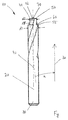
- the figure shows a drill 10, which is suitable for hand-guided drilling a blind hole in a non-illustrated workpiece made of metal, in a side view.
- the drill 10 comprises a shaft 20 which defines a drilling direction 30 and has an axis of rotation 40 oriented in the drilling direction 30.
- end of the shaft 20 has a cutting edge 50 and a further cutting edge, not shown, which are arranged opposite to each other and symmetrical with respect to the rotation axis 40 and define by rotation about the rotation axis 40 together a blind hole diameter of the drilled blind hole ,
- the shaft 20 has a stop shoulder 55 with a stop surface 60 aligned perpendicular to the axis of rotation 40 and pointing in the direction of drilling 30.
- the stop shoulder 55 abuts against a surface of the workpiece, so that the distance of the stop surface 60 from the cutting edge 50 measured counter to the drilling direction 30 defines a blind hole depth of the drilled blind hole.
- the shaft 20 has a male end 80 for temporary attachment to a hand-held drill.
- the shaft 20 has an enveloping circle diameter changing along the axis of rotation 40.
- first shaft portion 41 of the shaft 40 of the enveloping circle diameter d1 is smaller than the blind hole diameter.
- second shaft portion 42 of the shaft 40 of the enveloping circle diameter d2 is constant and the same size as the blind hole diameter.
- the enveloping circle diameter d3 is greater than the blind hole diameter.
- the enveloping circle diameter d1 in the first shaft section 41 increases continuously in the drilling direction 30, so that a conical enveloping surface is formed.
- the conical envelope surface is inclined relative to the drilling direction 30 by a cone angle ⁇ , which is 5 °.
- the enveloping circle diameter d2 in the second shaft section 42 is constant throughout, so that a circular-cylindrical envelope surface is formed, which may protect the cutting edge 50 from excessive wear.
- the shaft 20 at its pointing in the direction of drilling 30 end a centering tip 70 through which the axis of rotation 40 extends.
- the entire shaft 40 including the cutting edge 50 and the centering tip 70 is formed in one piece, so that the stop shoulder 55, the first shaft portion 41, the second shaft portion 42 and the cutting edge 50 of the same material, preferably a metal or alloy, particularly preferred a steel.
- the shank 20 has two helical grooves 90, which extend through the stop shoulder 55, the first shank portion 41 and the second shank portion 42, and of the cutting edge 50 and are limited by the other cutting edge.
Landscapes
- Engineering & Computer Science (AREA)
- Mechanical Engineering (AREA)
- Drilling Tools (AREA)
- Earth Drilling (AREA)
Priority Applications (8)
| Application Number | Priority Date | Filing Date | Title |
|---|---|---|---|
| EP16170048.9A EP3246120A1 (fr) | 2016-05-18 | 2016-05-18 | Perceuse a metaux |
| TW106108936A TWI640377B (zh) | 2016-05-18 | 2017-03-17 | Metal drill |
| CN201780028022.0A CN109070241A (zh) | 2016-05-18 | 2017-05-16 | 金属钻头 |
| PCT/EP2017/061646 WO2017198632A1 (fr) | 2016-05-18 | 2017-05-16 | Perceuse à métaux |
| JP2018560791A JP2019516571A (ja) | 2016-05-18 | 2017-05-16 | 金属ドリル |
| KR1020187033153A KR20190006497A (ko) | 2016-05-18 | 2017-05-16 | 금속 드릴 |
| US16/301,084 US20190184473A1 (en) | 2016-05-18 | 2017-05-16 | Metal drill |
| EP17723124.8A EP3458216A1 (fr) | 2016-05-18 | 2017-05-16 | Perceuse à métaux |
Applications Claiming Priority (1)
| Application Number | Priority Date | Filing Date | Title |
|---|---|---|---|
| EP16170048.9A EP3246120A1 (fr) | 2016-05-18 | 2016-05-18 | Perceuse a metaux |
Publications (1)
| Publication Number | Publication Date |
|---|---|
| EP3246120A1 true EP3246120A1 (fr) | 2017-11-22 |
Family
ID=56014876
Family Applications (2)
| Application Number | Title | Priority Date | Filing Date |
|---|---|---|---|
| EP16170048.9A Withdrawn EP3246120A1 (fr) | 2016-05-18 | 2016-05-18 | Perceuse a metaux |
| EP17723124.8A Withdrawn EP3458216A1 (fr) | 2016-05-18 | 2017-05-16 | Perceuse à métaux |
Family Applications After (1)
| Application Number | Title | Priority Date | Filing Date |
|---|---|---|---|
| EP17723124.8A Withdrawn EP3458216A1 (fr) | 2016-05-18 | 2017-05-16 | Perceuse à métaux |
Country Status (7)
| Country | Link |
|---|---|
| US (1) | US20190184473A1 (fr) |
| EP (2) | EP3246120A1 (fr) |
| JP (1) | JP2019516571A (fr) |
| KR (1) | KR20190006497A (fr) |
| CN (1) | CN109070241A (fr) |
| TW (1) | TWI640377B (fr) |
| WO (1) | WO2017198632A1 (fr) |
Citations (6)
| Publication number | Priority date | Publication date | Assignee | Title |
|---|---|---|---|---|
| DE8912860U1 (de) * | 1989-10-31 | 1990-02-01 | Hertel AG Werkzeuge + Hartstoffe, 8510 Fürth | Spiralbohrer |
| JPH04275813A (ja) * | 1991-03-01 | 1992-10-01 | Kobe Steel Ltd | ドリル |
| US20050019115A1 (en) * | 2003-07-24 | 2005-01-27 | Gatton Geoffrey L. | Tool and method for forming a valve stem hole |
| US20050135885A1 (en) * | 2003-12-22 | 2005-06-23 | Gatton Geoffrey L. | Tool and method for forming a lug hole |
| EP2239075A2 (fr) * | 2009-04-07 | 2010-10-13 | Sandvik Intellectual Property AB | Foret étagé solide |
| WO2010115404A1 (fr) * | 2009-03-30 | 2010-10-14 | Gühring Ohg | Outil étagé à plusieurs biseaux entraîné en rotation |
Family Cites Families (19)
| Publication number | Priority date | Publication date | Assignee | Title |
|---|---|---|---|---|
| DE2402516A1 (de) * | 1974-01-19 | 1975-07-31 | Paul Lobert | Verfahren und vorrichtung zur bestimmung der bohrtiefe bei sackbohrungen |
| DE3704106A1 (de) * | 1987-02-11 | 1988-08-25 | Hawera Praezisionswerkzeuge | Bohrwerkzeug zur bearbeitung von langspanenden werkstoffen |
| DE3828982A1 (de) * | 1988-08-26 | 1990-03-01 | Fischer Artur Werke Gmbh | Bohrvorrichtung zur herstellung von bohrloechern mit hinterschneidung |
| DE4014224A1 (de) * | 1990-05-04 | 1991-11-07 | Fischer Artur Werke Gmbh | Vorrichtung zur herstellung von bohrloechern mit hinterschneidung |
| JPH0929524A (ja) * | 1995-07-13 | 1997-02-04 | Izumi Saito | ハンドドリル用ドリル刃 |
| JP3720010B2 (ja) * | 2002-10-02 | 2005-11-24 | オーエスジー株式会社 | 深穴加工用ドリル |
| DE10347313A1 (de) * | 2003-10-08 | 2005-05-12 | Fischer Artur Werke Gmbh | Vorrichtung und Verfahren zur Bohrtiefeneinstellung an einer Handbohrmaschine |
| WO2006001819A1 (fr) * | 2003-11-12 | 2006-01-05 | Donald Nadler | Trepan destine a la mise en place d'un point d'ancrage, systeme et procede d'ancrage |
| KR20080111648A (ko) * | 2007-06-19 | 2008-12-24 | 예상백 | 드릴 |
| DE202010011574U1 (de) * | 2010-08-19 | 2011-02-17 | Albert, Helmut | Bohrer mit Skala und Bohrerhülse |
| JP5823840B2 (ja) * | 2011-11-30 | 2015-11-25 | 富士重工業株式会社 | ドリルおよび切削加工物の製造方法 |
| TWI532551B (zh) * | 2012-11-27 | 2016-05-11 | 創國興業有限公司 | 倒錐型鑽頭結構 |
| DE102013105015A1 (de) * | 2013-05-15 | 2014-11-20 | Gühring KG | Systemwerkzeug und Werkzeug zur spanabhebenden Bearbeitung |
| WO2015026955A1 (fr) * | 2013-08-21 | 2015-02-26 | Scianamblo Michael J | Perçage et alésage avec précession |
| DE202014103192U1 (de) * | 2014-06-02 | 2014-07-23 | Mikron Tool Sa Agno | Bohrwerkzeug |
| CN204639239U (zh) * | 2015-05-27 | 2015-09-16 | 启东市吕四科技创业中心有限公司 | 一种阶梯面多用开孔钻头 |
| CN204934687U (zh) * | 2015-09-08 | 2016-01-06 | 创国兴业有限公司 | 钻头结构 |
| CN105458355A (zh) * | 2015-12-03 | 2016-04-06 | 洛阳丰泰铝业有限公司 | 一种多功能螺旋钻头 |
| US20190076932A1 (en) * | 2017-09-14 | 2019-03-14 | Spirit Aerosystems, Inc. | Apparatus and method for minimizing elongation in drilled holes |
-
2016
- 2016-05-18 EP EP16170048.9A patent/EP3246120A1/fr not_active Withdrawn
-
2017
- 2017-03-17 TW TW106108936A patent/TWI640377B/zh not_active IP Right Cessation
- 2017-05-16 KR KR1020187033153A patent/KR20190006497A/ko not_active Withdrawn
- 2017-05-16 US US16/301,084 patent/US20190184473A1/en not_active Abandoned
- 2017-05-16 WO PCT/EP2017/061646 patent/WO2017198632A1/fr not_active Ceased
- 2017-05-16 EP EP17723124.8A patent/EP3458216A1/fr not_active Withdrawn
- 2017-05-16 JP JP2018560791A patent/JP2019516571A/ja active Pending
- 2017-05-16 CN CN201780028022.0A patent/CN109070241A/zh active Pending
Patent Citations (6)
| Publication number | Priority date | Publication date | Assignee | Title |
|---|---|---|---|---|
| DE8912860U1 (de) * | 1989-10-31 | 1990-02-01 | Hertel AG Werkzeuge + Hartstoffe, 8510 Fürth | Spiralbohrer |
| JPH04275813A (ja) * | 1991-03-01 | 1992-10-01 | Kobe Steel Ltd | ドリル |
| US20050019115A1 (en) * | 2003-07-24 | 2005-01-27 | Gatton Geoffrey L. | Tool and method for forming a valve stem hole |
| US20050135885A1 (en) * | 2003-12-22 | 2005-06-23 | Gatton Geoffrey L. | Tool and method for forming a lug hole |
| WO2010115404A1 (fr) * | 2009-03-30 | 2010-10-14 | Gühring Ohg | Outil étagé à plusieurs biseaux entraîné en rotation |
| EP2239075A2 (fr) * | 2009-04-07 | 2010-10-13 | Sandvik Intellectual Property AB | Foret étagé solide |
Also Published As
| Publication number | Publication date |
|---|---|
| KR20190006497A (ko) | 2019-01-18 |
| EP3458216A1 (fr) | 2019-03-27 |
| TW201741054A (zh) | 2017-12-01 |
| JP2019516571A (ja) | 2019-06-20 |
| TWI640377B (zh) | 2018-11-11 |
| CN109070241A (zh) | 2018-12-21 |
| US20190184473A1 (en) | 2019-06-20 |
| WO2017198632A1 (fr) | 2017-11-23 |
Similar Documents
| Publication | Publication Date | Title |
|---|---|---|
| DE3853518T2 (de) | Spiralbohrer. | |
| EP0151251B1 (fr) | Foret ayant plusieurs arêtes tranchantes | |
| DE4417166A1 (de) | Bohrgerät | |
| DE102014013210B4 (de) | Zerspanwerkzeug mit einem Kühlkanal | |
| DE102019211827B4 (de) | Bohrer und Verfahren zur Herstellung eines Bohrers | |
| DE102014207502B4 (de) | Rotationswerkzeug sowie Werkzeugkopf | |
| DE102015116623A1 (de) | Schaftfräser | |
| DE102016208228B4 (de) | Bohrer | |
| EP2431565A1 (fr) | Tête en métal dur pour un outil de traitement de matériau en matière solide | |
| DE102010002669A1 (de) | Drehantreibbares spanabhebendes Werkzeug | |
| DE4405987C2 (de) | Schaftfräser | |
| DE102015115548A1 (de) | Stabmesserkopf | |
| DE102013218321A1 (de) | Verfahren zur Herstellung eines Rundlaufwerkzeugs sowie Rundlaufwerkzeug | |
| EP2915613B1 (fr) | Foret à trou transversal | |
| DE112006004174T5 (de) | Spiralnut-Gewindeschneider | |
| EP3150314B1 (fr) | Fraise à queue | |
| DE102016005081A1 (de) | Schrumpffutter | |
| EP3246120A1 (fr) | Perceuse a metaux | |
| DE102014203327A1 (de) | Bohrwerkzeug | |
| DE202013101404U1 (de) | Bohrwerkzeug | |
| DE10338754C5 (de) | Werkzeug zur spanlosen Erzeugung eines Gewindes und Verfahren zur Herstellung eines Werkzeugs zur spanlosen Gewindeerzeugung | |
| DE202009010943U1 (de) | Werkzeug zur spanabhebenden Bearbeitung von Werkstücken | |
| EP3535080B1 (fr) | Outil de perçage | |
| DE102017212053A1 (de) | Rotationswerkzeug sowie Verfahren zur Herstellung eines Rotationswerkzeugs | |
| DE102016116279A1 (de) | Einschneidiges Fräswerkzeug |
Legal Events
| Date | Code | Title | Description |
|---|---|---|---|
| PUAI | Public reference made under article 153(3) epc to a published international application that has entered the european phase |
Free format text: ORIGINAL CODE: 0009012 |
|
| AK | Designated contracting states |
Kind code of ref document: A1 Designated state(s): AL AT BE BG CH CY CZ DE DK EE ES FI FR GB GR HR HU IE IS IT LI LT LU LV MC MK MT NL NO PL PT RO RS SE SI SK SM TR |
|
| AX | Request for extension of the european patent |
Extension state: BA ME |
|
| STAA | Information on the status of an ep patent application or granted ep patent |
Free format text: STATUS: THE APPLICATION IS DEEMED TO BE WITHDRAWN |
|
| 18D | Application deemed to be withdrawn |
Effective date: 20180523 |