EP3246202A1 - Point d'ancrage - Google Patents
Point d'ancrage Download PDFInfo
- Publication number
- EP3246202A1 EP3246202A1 EP17171044.5A EP17171044A EP3246202A1 EP 3246202 A1 EP3246202 A1 EP 3246202A1 EP 17171044 A EP17171044 A EP 17171044A EP 3246202 A1 EP3246202 A1 EP 3246202A1
- Authority
- EP
- European Patent Office
- Prior art keywords
- pivoting
- pivot
- parts
- zurranker
- opening
- Prior art date
- Legal status (The legal status is an assumption and is not a legal conclusion. Google has not performed a legal analysis and makes no representation as to the accuracy of the status listed.)
- Granted
Links
Images



Classifications
-
- B—PERFORMING OPERATIONS; TRANSPORTING
- B60—VEHICLES IN GENERAL
- B60P—VEHICLES ADAPTED FOR LOAD TRANSPORTATION OR TO TRANSPORT, TO CARRY, OR TO COMPRISE SPECIAL LOADS OR OBJECTS
- B60P7/00—Securing or covering of load on vehicles
- B60P7/06—Securing of load
- B60P7/08—Securing to the vehicle floor or sides
- B60P7/0807—Attachment points
-
- B—PERFORMING OPERATIONS; TRANSPORTING
- B60—VEHICLES IN GENERAL
- B60P—VEHICLES ADAPTED FOR LOAD TRANSPORTATION OR TO TRANSPORT, TO CARRY, OR TO COMPRISE SPECIAL LOADS OR OBJECTS
- B60P3/00—Vehicles adapted to transport, to carry or to comprise special loads or objects
- B60P3/06—Vehicles adapted to transport, to carry or to comprise special loads or objects for carrying vehicles
- B60P3/07—Vehicles adapted to transport, to carry or to comprise special loads or objects for carrying vehicles for carrying road vehicles
- B60P3/073—Vehicle retainers
- B60P3/079—Tie-down retainers
Definitions
- the invention relates to a Zurranker with the features of the preamble of claim 1 and a use of such Zurrankers.
- the object of the invention is to provide a simpler, universally applicable Zurrankers, which is particularly suitable for lashing cargo on a commercial vehicle.
- Such a container can be made small, has only a few parts and can be anchored to a single anchoring opening. Since the pivoting parts extend transversely to a pivot axis passing through the joint, in the second pivoting position (blocking position of the pivoting parts or lashing position of the locking device) they can engage behind an edge forming the anchoring opening. Because the pivot parts are arranged side by side in the direction of the pivot axis, each having at least one opening and the openings arranged in or on different pivoting parts in the second pivot position is easily in the second pivot position, a locking of the pivot parts with respect to a pivoting of the pivot parts to each other about the pivot axis by inserting a locking means in the aligned openings possible. In a minimal variant, the invention thus comes with only three parts (first pivot part, second pivot part, joint). In this variant, the aligned openings can serve as Zurrantsch.
- an anchoring opening can be understood, for example, a through hole, in particular a slot in a plate, such as a perforated plate.
- an anchoring opening in the form of a T-groove is conceivable.
- At least the first pivoting part has at least one stop, at least the first pivoting part can be supported on an edge of an anchoring opening. As a result, a dropping in of the Zurrankers can be avoided in the anchoring opening. Also, a transfer of the limiter from the first pivot position into the second pivot position can be facilitated because the first pivot part can be pivoted by the support relative to the anchoring opening.
- the projections extend at different pivoting parts in different directions. This can be a spreading of the Zurrankers be facilitated in an anchoring opening. By such a course, a gripping behind an anchoring opening can be facilitated.
- the extensions may run transversely to the pivot axis. As a result, it can be easily achieved that the extensions have different distances in the pivoting position of the locking device. Also, this can reach behind an anchoring opening by the extensions be achieved particularly easily when pivoting the pivot parts to each other.
- the passenger may also be advantageous for the passenger to have a blocking means. As a result, a locking of the pivoting parts in relation to a pivoting of the pivoting parts relative to one another can be made possible.
- the locking means has the Zurrantsch and is preferably annular.
- the blocking means can thereby assume the double function of blocking the pivoting parts with respect to pivoting of the pivoting parts relative to one another and providing a ratcheting impact, that is to say an attachment point for, for example, a lashing strap.
- a substantially annular design of the locking means it can lead to an advantageous embodiment of the locking means and the trained by this Zurrantschs.
- the operator can also be advantageous for the operator to have a blocking means which can be inserted in the second pivoting position of the pivoting parts into the aligned openings for locking the pivoting parts relative to pivoting of the pivoting parts relative to one another about the pivot axis.
- the retractor can be kept permanently in the second pivot position.
- the Zurranker can thereby be anchored in the anchoring opening, in particular against tensile loads.
- the first pivoting part additionally has at least one stop for support on an edge of an anchoring opening, the retractor can be anchored in the anchoring opening against thrust and tensile loads.
- the blocking means can be designed to be detachable.
- the joint is arranged eccentrically on the pivoting parts and the openings centrally on the pivoting parts are arranged.
- the openings arranged on or in different pivoting parts are aligned in the second pivoting position and, when the pivoting parts are pivoted relative to one another, come out of this second pivoting position. If, in the second pivoting position, a blocking means is introduced into the openings, then such pivoting of the pivoting parts relative to one another can be prevented.
- first and the second pivot part have a backdrop and the openings are formed in the respective scenes.
- the scenes and the openings may be formed as a through hole and / or as recesses in the pivoting parts.
- a blocking means is movable and arranged in or on the first pivot part gate has a release opening connected to the opening, wherein at a arranged in the release opening blocking means provided in the second pivot position locks the pivot parts is lifted, and the pivoting parts are in the first pivot position.
- a method or movement of the locking means from the opening into the release opening a blockage of the relative pivotability of the pivot parts to each other can be canceled. Also, by such a method or such a movement of the limiter can be transferred from the second pivot position to the first pivot position.
- Characterized in that the arranged in or on the first pivot part gate has a release opening connected to the opening can be effected with appropriate shaping of the openings and the scenes in a process or moving a locking means in the release opening a pivoting of the pivot parts to each other.
- the driveline when it is raised when it is in the second swivel position of the swiveling parts, it is at least connected by the own weight of the dredger or by a contact one of the extensions on a border of an anchoring opening the blocking means in the release opening device.
- the blocking means when the driveline is raised when it is in the second swivel position of the swiveling parts, it is at least connected by the own weight of the dredger or by a contact one of the extensions on a border of an anchoring opening the blocking means in the release opening device.
- an intentional transfer of the limiter from the second pivoting position of the pivoting parts into the first pivoting position of the pivoting parts relative to one another is made possible. This may, for example, allow an intentional release of a anchor anchored in an anchoring opening. Also, this can be held by his own weight in the first pivot position a Zurranker.
- a lashing strap is connected to the trailer. This can create a particularly easy-to-use lashing.
- a hook connected to the lashing strap can serve as a blocking means.
- a hook can also be used with a screw or locking pin closable bracket (shackle), which can also be assumed by this the double function of the locking means and the Zurrantschs.
- the lane plate may be formed as a perforated plate and the Zurranker be anchored in holes of the perforated plate.
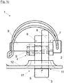
- the Zurranker 1 a first and a second plate-shaped pivoting part 2, 3, which are connected to each other via a hinge 4 and with respect to a going through the hinge 4 pivot axis S are pivotable relative to each other.
- the pivoting parts 2, 3 extend transversely to the pivot axis S.
- Each pivoting part 2, 3 has an extension 5 (only in the figures). It can per swivel part 2, 3 more, preferably mutually parallel extensions 5 may be provided.
- the arranged on different pivot parts 2, 3 extensions 5 extend in different directions. In the second pivoting position of the pivoting parts 2, 3, the extensions 5 extend in at least approximately opposite directions.
- the pivoting parts 2, 3 each have at least one opening 6, 6 ', 7, 7'. Openings 6, 6 ', 7, 7' which are arranged on or in different pivoting parts 2, 3, are aligned in the second pivoting position, so that the pivoting parts 2, 3 in the second pivoting position by inserting a locking means 9 in the aligned openings 6, 7th or possibly 6 ', 7' in relation to a pivoting of the pivoting parts 2, 3 to each other about the pivot axis S are lockable.
- the blocking means 9 may be part of the dresser 1, but this is not absolutely necessary.
- Fig. 1a are the pivot parts 2, 3 in the first pivot position and the arranged on different pivot parts 2, 3 extensions 5 have a minimum distance from each other. In this position, the Zurranker 1 can be inserted into a formed on a perforated plate 12 anchoring opening 17.
- Fig. 1b are the pivoting parts 2, 3 in the second pivot position and arranged on different pivot parts 2, 3 extensions 5 have a maximum distance from each other. So they can engage behind the perforated plate 12 in the region of the anchoring opening 17 at the positions 10, 11 and the Zurranker 1 is anchored to the perforated plate 12.
- the opening 6 is formed as a recess on the first pivot part 2.
- the Zurrantsch 8 is formed in the form of a arranged on the first pivot part 2 eyelet.
- Fig. 1c is a side view along in Fig. 1b shown line A - A and shows the type of locking in this embodiment.
- the pivoting parts 2, 3 are in the second pivoting position.
- a locking means 9 is formed here as a bolt with a securing bracket serving.
- the locking means 9 may be formed, for example, as a spring-loaded pressure piece.
- the blocking means 9 has been introduced by an operator in the second pivoting position of the pivoting parts 2, 3 into an opening 7 of the second pivoting part 3 and protrudes into the opening 6 arranged on the first pivoting part 2.
- Zurranker 1 In the case of a tensile load acting on Zurrantsch 8 Zurranker 1 can be prevented by the introduced into the openings 6, 7 blocking means 9, a pivoting of the pivot parts 2.3 to each other and so the Zurranker 1 are securely anchored in the anchoring opening 17.
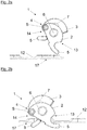
- Fig. 2 shows a further embodiment of the Zurrankers 1, wherein in contrast to the in Fig. 1 embodiment shown, the openings 6, 7th are formed as passage openings in the material of the pivoting parts 2, 3 and in which additionally stops 13, 14 are arranged on the first pivot part 2.
- the Fig. 2a to 2e show a sequence of using the Zurrankers for anchoring a cargo, not shown, to a commercial vehicle, also not shown.
- the pivoting parts 2, 3 in the second pivot position In the Fig. 2d and 2e are the pivoting parts 2, 3 in the second pivot position.
- Fig. 2a 1 shows a pranger 1 which is arranged above a perforated plate 12 which is shown in the region of a selected anchoring opening 17.
- Fig. 2b The stops 13, 14 allow a supporting of the first pivoting part 2 at an upper side of a border of the anchoring opening 17. Because the first pivoting part 2 and thus the dresser 1 at are supported by the border, initially protrude only the extensions 5 of the pivoting parts 2, 3 in the anchoring opening 17 (see. Fig. 2b and 2c ). This prevents falling through of the dresser 1 through the perforated plate 12.
- By further lowering the Zurrankers 1 relative to the perforated plate 12 is a pivoting of the first pivot part 2 relative to the perforated plate 12 and the second pivot part 3.
- Fig. 2d shows the situation after the pivoting parts 2, 3 have been pivoted into the second pivoting position.
- the stops 13, 14 of the first pivoting part 2 are based on the border of the anchoring opening 17 from (due to the location of the in the Fig. 2d selected cutting plane of the perforated plate 12 is the Installation of the pivoting part 2 at the border of the opening of this figure is not apparent, but is for example in Fig. 4d clearly).
- the openings 6, 7 are aligned. In this way, a locking of the pivoting parts 2, 3 relative to each other with respect to a pivoting about the pivot axis S by inserting a locking means 9 (not shown, but see Fig. 2e ) take place in the aligned openings 6, 7.
- Fig. 2e shows the Zurranker 1 in the locked state.
- a hook 16 is inserted, with a lashing strap 18 is connected.
- the openings 6, 7 serve in this embodiment as Zurrantsch eighth
- Fig. 3 shows a further embodiment of the Zurrankers 1, in which as well as in Fig. 2 the openings 6, 7 are formed as passage openings in the material of the pivoting parts 2, 3 and in which also stops 13, 14 are arranged on the first pivot part 2.
- Fig. 2 have the first and the second pivot part 2, 3, a link 19, 20 and the openings 6, 6 ', 7, 7' are formed in the respective scenes 19, 20, wherein in or on the link 19, 20, a blocking means.
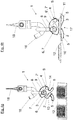
- the Fig. 4a to 4f show a sequence of using the Zurrankers for anchoring a cargo, not shown, to a commercial vehicle, also not shown.
- the Fig. 4g and 4h show rear views of the Fig. 4b or 4e.
- Fig. 4a shows a Zurranker 1 with two pivoted about the pivot axis S in the first pivot position swivel parts 2, 3.
- a closed with a bolt bracket (shackles) forms the Zurrantsch 8 and the locking means 9 from.
- a lashing strap 18 is struck with a hook 16 on the bump stop 8.
- the lashing strap 18 can strike directly on the ratchet 8.
- a captive lashing device can be provided.
- the Zurranker 1 is in Fig. 4a held by its own weight in the first pivot position, since the locking means 9 is located in the release opening 15 of the first pivot member 2 and is urged by the corresponding orientation of the release hole 15 and by the influence of gravity in this.
- the second pivot member 3 has been pivoted (raised) by the entry of the locking means in the release opening 15 of the first pivot member 2 and the limiter 1 thus has been brought into the first pivot position (see also Fig. 4g ).
- the Fig. 4b to 4f show a sequence of anchoring of the anchor 1 in an anchoring opening 17 in a perforated plate 12th
- Fig. 4b In this case, a retainer 1 arranged above a perforated plate 12 shown in the region of a selected anchoring opening 17 is shown.
- Fig. 4g shows a rear view of the Fig. 4b
- Fig. 4c the container 1 has been partially inserted into the anchoring opening 17.
- the release opening 15 of the restraint come to rest at a suspension on Zurrantsch 8 so that the extension 5 of the first pivoting part 2 protrudes when lowering the Zurrankers 1 as the first in the anchoring opening 17, thereby introducing the Zurrankers 1 can be facilitated.
- a further lowering the Zurrankers 1 can this as in Fig. 4d shown with the stop 13 come to rest on a border of the anchoring opening 17 to plant.
- the stops 13, 14 generally allow a supporting of the first pivoting part 2 at an upper side of a border of the anchoring opening 17, whereby a falling through of the dresser 1 through the perforated plate 12 can be prevented.
- a pivoting of the first pivot part 2 relative to the perforated plate 12 and the second pivot part 3 is carried out.
- the second pivot part 3 pivots relative to the perforated plate 12 and the first pivot part 2, so that the extensions 5 engage behind the border of the anchoring opening 17.
- the locking means 9 has been moved in the release opening 15, whereby the Zurranker 1 could be pivoted in the direction of its first pivot position. Upon further pivoting of the pivoting parts 2, 3 to each other, the locking means 9 escape from the release opening 15 of the first pivot member 2 and in the aligned in the first pivot position openings 6, 7 and 6 ', 7' are introduced.
- Fig. 4e shows the situation after further pivoting of the pivoting parts 2, 3 in the second pivot position, wherein the locking means 9 are inserted into the aligned in this first pivotal position openings 6, 7.
- the stops 13, 14 of the first pivoting part 2 are supported on the edge of the anchoring opening 17.
Landscapes
- Engineering & Computer Science (AREA)
- Transportation (AREA)
- Mechanical Engineering (AREA)
- Hooks, Suction Cups, And Attachment By Adhesive Means (AREA)
- Ladders (AREA)
Applications Claiming Priority (1)
| Application Number | Priority Date | Filing Date | Title |
|---|---|---|---|
| AT504532016 | 2016-05-17 |
Publications (2)
| Publication Number | Publication Date |
|---|---|
| EP3246202A1 true EP3246202A1 (fr) | 2017-11-22 |
| EP3246202B1 EP3246202B1 (fr) | 2020-09-09 |
Family
ID=58709360
Family Applications (1)
| Application Number | Title | Priority Date | Filing Date |
|---|---|---|---|
| EP17171044.5A Active EP3246202B1 (fr) | 2016-05-17 | 2017-05-15 | Point d'ancrage |
Country Status (1)
| Country | Link |
|---|---|
| EP (1) | EP3246202B1 (fr) |
Families Citing this family (1)
| Publication number | Priority date | Publication date | Assignee | Title |
|---|---|---|---|---|
| DE102024119235B4 (de) * | 2024-07-05 | 2026-01-22 | Deutsche Post Ag | Vorrichtung zum Bereitstellen von einer Barriere, Verwendung und Rollendeck |
Citations (6)
| Publication number | Priority date | Publication date | Assignee | Title |
|---|---|---|---|---|
| DE2945550A1 (de) * | 1978-11-20 | 1980-05-29 | William L Mccullough | Lastentraggestell |
| US20070207003A1 (en) * | 2006-03-01 | 2007-09-06 | Warren Roh | Cargo restraint anchor device for pick-up trucks |
| US20080304930A1 (en) | 2007-06-08 | 2008-12-11 | Holland Company | Wheel restraint assembly and method |
| US20100143064A1 (en) * | 2008-03-11 | 2010-06-10 | Gomez David L | Adjustable tie-down apparatus for pickup trucks |
| DE202010008543U1 (de) * | 2010-09-15 | 2010-11-25 | MÜNZ-Fahrzeugbau GmbH & Co. KG | Verzurrösenanordnung für ein Fahrzeug mit einem Ladeboden |
| WO2011143042A1 (fr) * | 2010-05-10 | 2011-11-17 | Maaj Research And Development, Inc. | Dispositif d'ancrage portatif et amovible pour rainures de plateforme de camion |
-
2017
- 2017-05-15 EP EP17171044.5A patent/EP3246202B1/fr active Active
Patent Citations (6)
| Publication number | Priority date | Publication date | Assignee | Title |
|---|---|---|---|---|
| DE2945550A1 (de) * | 1978-11-20 | 1980-05-29 | William L Mccullough | Lastentraggestell |
| US20070207003A1 (en) * | 2006-03-01 | 2007-09-06 | Warren Roh | Cargo restraint anchor device for pick-up trucks |
| US20080304930A1 (en) | 2007-06-08 | 2008-12-11 | Holland Company | Wheel restraint assembly and method |
| US20100143064A1 (en) * | 2008-03-11 | 2010-06-10 | Gomez David L | Adjustable tie-down apparatus for pickup trucks |
| WO2011143042A1 (fr) * | 2010-05-10 | 2011-11-17 | Maaj Research And Development, Inc. | Dispositif d'ancrage portatif et amovible pour rainures de plateforme de camion |
| DE202010008543U1 (de) * | 2010-09-15 | 2010-11-25 | MÜNZ-Fahrzeugbau GmbH & Co. KG | Verzurrösenanordnung für ein Fahrzeug mit einem Ladeboden |
Also Published As
| Publication number | Publication date |
|---|---|
| EP3246202B1 (fr) | 2020-09-09 |
Similar Documents
| Publication | Publication Date | Title |
|---|---|---|
| DE3830493C2 (de) | Gurtkraft-Begrenzungsvorrichtung | |
| DE10359226B4 (de) | Rollstuhl-Halterungssystem | |
| DE4325662A1 (de) | Vorrichtung zur Höhenverstellung eines Sicherheitsgurtbeschlages | |
| DE202018106361U1 (de) | Beschlag zur Ladungssicherung | |
| EP3763238B1 (fr) | Fermeture de ceinture, système de fermeture de ceinture et ceinture de sécurité pour avion | |
| DE102019219001A1 (de) | Hakenflasche für einen Kran | |
| DE10106920A1 (de) | Vorrichtung zur Sicherung von Ladegut | |
| EP3246202B1 (fr) | Point d'ancrage | |
| EP3033961B1 (fr) | Systeme de boucle de ceinture | |
| DE10120538A1 (de) | Halteverriegelung zum Befestigen eines Auto-Kindersitzes an einer Verankerung | |
| EP2805083B1 (fr) | Connexion de câble et manchon de câble pour une connexion de câble | |
| AT15807U1 (de) | Verwendung eines Zurrankers zum Verankern eines Zurrmittels | |
| DE102015121796A1 (de) | Rundgreifer | |
| EP3463239B1 (fr) | Aide à la mobilité | |
| DE29716096U1 (de) | Schnellverschluß | |
| AT504478B1 (de) | Niederhalter | |
| DE60027948T2 (de) | Vorrichtung zur Sicherung von Lasten | |
| EP0212322A2 (fr) | Attelage de remorque détachable | |
| EP4132874B1 (fr) | Crochet de transport | |
| DE102012111642A1 (de) | Nutzfahrzeugaufbau mit einer Schiebeplane, Verfahren zur Herstellung eines derartigen Nutzfahrzeugaufbaus und Nutzfahrzeug mit einem derartigen Nutzfahrzeugaufbau | |
| AT523664B1 (de) | Transporthaken | |
| DE202020106208U1 (de) | Modul für einen Förderer und entsprechenden Verbindungsbolzen der Bauteile eines jeden Moduls | |
| DE102006021887B4 (de) | Verriegelungsvorrichtung für einen Fahrzeugsitz | |
| EP3742021B1 (fr) | Griffe de raccourcissement permettant de serrer une chaîne d'amarrage | |
| DE102015109172B4 (de) | Nutzfahrzeugaufbau mit einer Plane, Nutzfahrzeug mit einem derartigen Nutzfahrzeugaufbau und Verfahren zur Herstellung eines Nutzfahrzeugaufbaus |
Legal Events
| Date | Code | Title | Description |
|---|---|---|---|
| PUAI | Public reference made under article 153(3) epc to a published international application that has entered the european phase |
Free format text: ORIGINAL CODE: 0009012 |
|
| STAA | Information on the status of an ep patent application or granted ep patent |
Free format text: STATUS: THE APPLICATION HAS BEEN PUBLISHED |
|
| AK | Designated contracting states |
Kind code of ref document: A1 Designated state(s): AL AT BE BG CH CY CZ DE DK EE ES FI FR GB GR HR HU IE IS IT LI LT LU LV MC MK MT NL NO PL PT RO RS SE SI SK SM TR |
|
| AX | Request for extension of the european patent |
Extension state: BA ME |
|
| STAA | Information on the status of an ep patent application or granted ep patent |
Free format text: STATUS: REQUEST FOR EXAMINATION WAS MADE |
|
| 17P | Request for examination filed |
Effective date: 20180518 |
|
| RBV | Designated contracting states (corrected) |
Designated state(s): AL AT BE BG CH CY CZ DE DK EE ES FI FR GB GR HR HU IE IS IT LI LT LU LV MC MK MT NL NO PL PT RO RS SE SI SK SM TR |
|
| GRAP | Despatch of communication of intention to grant a patent |
Free format text: ORIGINAL CODE: EPIDOSNIGR1 |
|
| STAA | Information on the status of an ep patent application or granted ep patent |
Free format text: STATUS: GRANT OF PATENT IS INTENDED |
|
| RIC1 | Information provided on ipc code assigned before grant |
Ipc: B60P 3/077 20060101AFI20191129BHEP Ipc: B60P 3/079 20060101ALI20191129BHEP Ipc: B60P 7/08 20060101ALI20191129BHEP |
|
| INTG | Intention to grant announced |
Effective date: 20191220 |
|
| GRAS | Grant fee paid |
Free format text: ORIGINAL CODE: EPIDOSNIGR3 |
|
| GRAA | (expected) grant |
Free format text: ORIGINAL CODE: 0009210 |
|
| STAA | Information on the status of an ep patent application or granted ep patent |
Free format text: STATUS: THE PATENT HAS BEEN GRANTED |
|
| AK | Designated contracting states |
Kind code of ref document: B1 Designated state(s): AL AT BE BG CH CY CZ DE DK EE ES FI FR GB GR HR HU IE IS IT LI LT LU LV MC MK MT NL NO PL PT RO RS SE SI SK SM TR |
|
| REG | Reference to a national code |
Ref country code: GB Ref legal event code: FG4D Free format text: NOT ENGLISH |
|
| REG | Reference to a national code |
Ref country code: AT Ref legal event code: REF Ref document number: 1311189 Country of ref document: AT Kind code of ref document: T Effective date: 20200915 Ref country code: CH Ref legal event code: EP |
|
| REG | Reference to a national code |
Ref country code: IE Ref legal event code: FG4D Free format text: LANGUAGE OF EP DOCUMENT: GERMAN |
|
| REG | Reference to a national code |
Ref country code: DE Ref legal event code: R096 Ref document number: 502017007117 Country of ref document: DE |
|
| REG | Reference to a national code |
Ref country code: LT Ref legal event code: MG4D |
|
| PG25 | Lapsed in a contracting state [announced via postgrant information from national office to epo] |
Ref country code: LT Free format text: LAPSE BECAUSE OF FAILURE TO SUBMIT A TRANSLATION OF THE DESCRIPTION OR TO PAY THE FEE WITHIN THE PRESCRIBED TIME-LIMIT Effective date: 20200909 Ref country code: SE Free format text: LAPSE BECAUSE OF FAILURE TO SUBMIT A TRANSLATION OF THE DESCRIPTION OR TO PAY THE FEE WITHIN THE PRESCRIBED TIME-LIMIT Effective date: 20200909 Ref country code: BG Free format text: LAPSE BECAUSE OF FAILURE TO SUBMIT A TRANSLATION OF THE DESCRIPTION OR TO PAY THE FEE WITHIN THE PRESCRIBED TIME-LIMIT Effective date: 20201209 Ref country code: GR Free format text: LAPSE BECAUSE OF FAILURE TO SUBMIT A TRANSLATION OF THE DESCRIPTION OR TO PAY THE FEE WITHIN THE PRESCRIBED TIME-LIMIT Effective date: 20201210 Ref country code: FI Free format text: LAPSE BECAUSE OF FAILURE TO SUBMIT A TRANSLATION OF THE DESCRIPTION OR TO PAY THE FEE WITHIN THE PRESCRIBED TIME-LIMIT Effective date: 20200909 Ref country code: NO Free format text: LAPSE BECAUSE OF FAILURE TO SUBMIT A TRANSLATION OF THE DESCRIPTION OR TO PAY THE FEE WITHIN THE PRESCRIBED TIME-LIMIT Effective date: 20201209 Ref country code: HR Free format text: LAPSE BECAUSE OF FAILURE TO SUBMIT A TRANSLATION OF THE DESCRIPTION OR TO PAY THE FEE WITHIN THE PRESCRIBED TIME-LIMIT Effective date: 20200909 |
|
| PG25 | Lapsed in a contracting state [announced via postgrant information from national office to epo] |
Ref country code: PL Free format text: LAPSE BECAUSE OF FAILURE TO SUBMIT A TRANSLATION OF THE DESCRIPTION OR TO PAY THE FEE WITHIN THE PRESCRIBED TIME-LIMIT Effective date: 20200909 Ref country code: RS Free format text: LAPSE BECAUSE OF FAILURE TO SUBMIT A TRANSLATION OF THE DESCRIPTION OR TO PAY THE FEE WITHIN THE PRESCRIBED TIME-LIMIT Effective date: 20200909 Ref country code: LV Free format text: LAPSE BECAUSE OF FAILURE TO SUBMIT A TRANSLATION OF THE DESCRIPTION OR TO PAY THE FEE WITHIN THE PRESCRIBED TIME-LIMIT Effective date: 20200909 |
|
| PG25 | Lapsed in a contracting state [announced via postgrant information from national office to epo] |
Ref country code: EE Free format text: LAPSE BECAUSE OF FAILURE TO SUBMIT A TRANSLATION OF THE DESCRIPTION OR TO PAY THE FEE WITHIN THE PRESCRIBED TIME-LIMIT Effective date: 20200909 Ref country code: SM Free format text: LAPSE BECAUSE OF FAILURE TO SUBMIT A TRANSLATION OF THE DESCRIPTION OR TO PAY THE FEE WITHIN THE PRESCRIBED TIME-LIMIT Effective date: 20200909 Ref country code: RO Free format text: LAPSE BECAUSE OF FAILURE TO SUBMIT A TRANSLATION OF THE DESCRIPTION OR TO PAY THE FEE WITHIN THE PRESCRIBED TIME-LIMIT Effective date: 20200909 Ref country code: PT Free format text: LAPSE BECAUSE OF FAILURE TO SUBMIT A TRANSLATION OF THE DESCRIPTION OR TO PAY THE FEE WITHIN THE PRESCRIBED TIME-LIMIT Effective date: 20210111 Ref country code: CZ Free format text: LAPSE BECAUSE OF FAILURE TO SUBMIT A TRANSLATION OF THE DESCRIPTION OR TO PAY THE FEE WITHIN THE PRESCRIBED TIME-LIMIT Effective date: 20200909 |
|
| PG25 | Lapsed in a contracting state [announced via postgrant information from national office to epo] |
Ref country code: AL Free format text: LAPSE BECAUSE OF FAILURE TO SUBMIT A TRANSLATION OF THE DESCRIPTION OR TO PAY THE FEE WITHIN THE PRESCRIBED TIME-LIMIT Effective date: 20200909 Ref country code: ES Free format text: LAPSE BECAUSE OF FAILURE TO SUBMIT A TRANSLATION OF THE DESCRIPTION OR TO PAY THE FEE WITHIN THE PRESCRIBED TIME-LIMIT Effective date: 20200909 Ref country code: IS Free format text: LAPSE BECAUSE OF FAILURE TO SUBMIT A TRANSLATION OF THE DESCRIPTION OR TO PAY THE FEE WITHIN THE PRESCRIBED TIME-LIMIT Effective date: 20210109 |
|
| REG | Reference to a national code |
Ref country code: DE Ref legal event code: R097 Ref document number: 502017007117 Country of ref document: DE |
|
| PG25 | Lapsed in a contracting state [announced via postgrant information from national office to epo] |
Ref country code: SK Free format text: LAPSE BECAUSE OF FAILURE TO SUBMIT A TRANSLATION OF THE DESCRIPTION OR TO PAY THE FEE WITHIN THE PRESCRIBED TIME-LIMIT Effective date: 20200909 |
|
| PLBE | No opposition filed within time limit |
Free format text: ORIGINAL CODE: 0009261 |
|
| STAA | Information on the status of an ep patent application or granted ep patent |
Free format text: STATUS: NO OPPOSITION FILED WITHIN TIME LIMIT |
|
| 26N | No opposition filed |
Effective date: 20210610 |
|
| PG25 | Lapsed in a contracting state [announced via postgrant information from national office to epo] |
Ref country code: DK Free format text: LAPSE BECAUSE OF FAILURE TO SUBMIT A TRANSLATION OF THE DESCRIPTION OR TO PAY THE FEE WITHIN THE PRESCRIBED TIME-LIMIT Effective date: 20200909 Ref country code: SI Free format text: LAPSE BECAUSE OF FAILURE TO SUBMIT A TRANSLATION OF THE DESCRIPTION OR TO PAY THE FEE WITHIN THE PRESCRIBED TIME-LIMIT Effective date: 20200909 |
|
| REG | Reference to a national code |
Ref country code: NL Ref legal event code: FP |
|
| REG | Reference to a national code |
Ref country code: CH Ref legal event code: PL |
|
| GBPC | Gb: european patent ceased through non-payment of renewal fee |
Effective date: 20210515 |
|
| PG25 | Lapsed in a contracting state [announced via postgrant information from national office to epo] |
Ref country code: CH Free format text: LAPSE BECAUSE OF NON-PAYMENT OF DUE FEES Effective date: 20210531 Ref country code: LI Free format text: LAPSE BECAUSE OF NON-PAYMENT OF DUE FEES Effective date: 20210531 Ref country code: LU Free format text: LAPSE BECAUSE OF NON-PAYMENT OF DUE FEES Effective date: 20210515 Ref country code: MC Free format text: LAPSE BECAUSE OF FAILURE TO SUBMIT A TRANSLATION OF THE DESCRIPTION OR TO PAY THE FEE WITHIN THE PRESCRIBED TIME-LIMIT Effective date: 20200909 |
|
| REG | Reference to a national code |
Ref country code: BE Ref legal event code: MM Effective date: 20210531 |
|
| PG25 | Lapsed in a contracting state [announced via postgrant information from national office to epo] |
Ref country code: IE Free format text: LAPSE BECAUSE OF NON-PAYMENT OF DUE FEES Effective date: 20210515 Ref country code: GB Free format text: LAPSE BECAUSE OF NON-PAYMENT OF DUE FEES Effective date: 20210515 |
|
| PG25 | Lapsed in a contracting state [announced via postgrant information from national office to epo] |
Ref country code: BE Free format text: LAPSE BECAUSE OF NON-PAYMENT OF DUE FEES Effective date: 20210531 |
|
| PG25 | Lapsed in a contracting state [announced via postgrant information from national office to epo] |
Ref country code: HU Free format text: LAPSE BECAUSE OF FAILURE TO SUBMIT A TRANSLATION OF THE DESCRIPTION OR TO PAY THE FEE WITHIN THE PRESCRIBED TIME-LIMIT; INVALID AB INITIO Effective date: 20170515 |
|
| PG25 | Lapsed in a contracting state [announced via postgrant information from national office to epo] |
Ref country code: CY Free format text: LAPSE BECAUSE OF FAILURE TO SUBMIT A TRANSLATION OF THE DESCRIPTION OR TO PAY THE FEE WITHIN THE PRESCRIBED TIME-LIMIT Effective date: 20200909 |
|
| PG25 | Lapsed in a contracting state [announced via postgrant information from national office to epo] |
Ref country code: MK Free format text: LAPSE BECAUSE OF FAILURE TO SUBMIT A TRANSLATION OF THE DESCRIPTION OR TO PAY THE FEE WITHIN THE PRESCRIBED TIME-LIMIT Effective date: 20200909 |
|
| PG25 | Lapsed in a contracting state [announced via postgrant information from national office to epo] |
Ref country code: TR Free format text: LAPSE BECAUSE OF FAILURE TO SUBMIT A TRANSLATION OF THE DESCRIPTION OR TO PAY THE FEE WITHIN THE PRESCRIBED TIME-LIMIT Effective date: 20200909 |
|
| PG25 | Lapsed in a contracting state [announced via postgrant information from national office to epo] |
Ref country code: MT Free format text: LAPSE BECAUSE OF FAILURE TO SUBMIT A TRANSLATION OF THE DESCRIPTION OR TO PAY THE FEE WITHIN THE PRESCRIBED TIME-LIMIT Effective date: 20200909 |
|
| PGFP | Annual fee paid to national office [announced via postgrant information from national office to epo] |
Ref country code: NL Payment date: 20250530 Year of fee payment: 9 |
|
| PGFP | Annual fee paid to national office [announced via postgrant information from national office to epo] |
Ref country code: DE Payment date: 20250606 Year of fee payment: 9 |
|
| PGFP | Annual fee paid to national office [announced via postgrant information from national office to epo] |
Ref country code: IT Payment date: 20250528 Year of fee payment: 9 |
|
| PGFP | Annual fee paid to national office [announced via postgrant information from national office to epo] |
Ref country code: FR Payment date: 20250527 Year of fee payment: 9 |
|
| PGFP | Annual fee paid to national office [announced via postgrant information from national office to epo] |
Ref country code: AT Payment date: 20250528 Year of fee payment: 9 |