EP4132874B1 - Crochet de transport - Google Patents
Crochet de transport Download PDFInfo
- Publication number
- EP4132874B1 EP4132874B1 EP21716397.1A EP21716397A EP4132874B1 EP 4132874 B1 EP4132874 B1 EP 4132874B1 EP 21716397 A EP21716397 A EP 21716397A EP 4132874 B1 EP4132874 B1 EP 4132874B1
- Authority
- EP
- European Patent Office
- Prior art keywords
- hook
- transport
- section
- securing
- hole
- Prior art date
- Legal status (The legal status is an assumption and is not a legal conclusion. Google has not performed a legal analysis and makes no representation as to the accuracy of the status listed.)
- Active
Links
Images




Classifications
-
- B—PERFORMING OPERATIONS; TRANSPORTING
- B66—HOISTING; LIFTING; HAULING
- B66C—CRANES; LOAD-ENGAGING ELEMENTS OR DEVICES FOR CRANES, CAPSTANS, WINCHES, OR TACKLES
- B66C1/00—Load-engaging elements or devices attached to lifting or lowering gear of cranes or adapted for connection therewith for transmitting lifting forces to articles or groups of articles
- B66C1/10—Load-engaging elements or devices attached to lifting or lowering gear of cranes or adapted for connection therewith for transmitting lifting forces to articles or groups of articles by mechanical means
- B66C1/12—Slings comprising chains, wires, ropes, or bands; Nets
- B66C1/14—Slings with hooks
-
- B—PERFORMING OPERATIONS; TRANSPORTING
- B66—HOISTING; LIFTING; HAULING
- B66C—CRANES; LOAD-ENGAGING ELEMENTS OR DEVICES FOR CRANES, CAPSTANS, WINCHES, OR TACKLES
- B66C1/00—Load-engaging elements or devices attached to lifting or lowering gear of cranes or adapted for connection therewith for transmitting lifting forces to articles or groups of articles
- B66C1/10—Load-engaging elements or devices attached to lifting or lowering gear of cranes or adapted for connection therewith for transmitting lifting forces to articles or groups of articles by mechanical means
- B66C1/22—Rigid members, e.g. L-shaped members, with parts engaging the under surface of the loads; Crane hooks
- B66C1/34—Crane hooks
- B66C1/36—Crane hooks with means, e.g. spring-biased detents, for preventing inadvertent disengagement of loads
-
- B—PERFORMING OPERATIONS; TRANSPORTING
- B66—HOISTING; LIFTING; HAULING
- B66C—CRANES; LOAD-ENGAGING ELEMENTS OR DEVICES FOR CRANES, CAPSTANS, WINCHES, OR TACKLES
- B66C1/00—Load-engaging elements or devices attached to lifting or lowering gear of cranes or adapted for connection therewith for transmitting lifting forces to articles or groups of articles
- B66C1/10—Load-engaging elements or devices attached to lifting or lowering gear of cranes or adapted for connection therewith for transmitting lifting forces to articles or groups of articles by mechanical means
- B66C1/62—Load-engaging elements or devices attached to lifting or lowering gear of cranes or adapted for connection therewith for transmitting lifting forces to articles or groups of articles by mechanical means comprising article-engaging members of a shape complementary to that of the articles to be handled
- B66C1/66—Load-engaging elements or devices attached to lifting or lowering gear of cranes or adapted for connection therewith for transmitting lifting forces to articles or groups of articles by mechanical means comprising article-engaging members of a shape complementary to that of the articles to be handled for engaging holes, recesses, or abutments on articles specially provided for facilitating handling thereof
Definitions
- the invention relates to a transport hook for lifting and moving a load, such as floor elements that are placed close together and are only accessible from above.
- a flooring support structure comprising a plurality of longitudinally aligned boards that are fastened to one another.
- the flooring support structure has at least two coupling openings in the form of elongated holes that run parallel to one another at a predetermined distance.
- the double hook can engage laterally in the flooring support structure.
- a double hook can engage through the holes into the interior of the flooring support structure, and the double hook can be connected to a lifting device.
- the US 9,741,847 B2 discloses an industrial mat having a support structure and two holes.
- the holes can be used to support the industrial mat.
- Other known tools for lifting plate-shaped elements include, for example, channel hooks or pliers-like tools for gripping the plate-shaped element on the outer sides.
- the US 845,724 discloses a pin-shaped element attached to a base for insertion into a drilled hole in a stone block.
- the stone block can be lifted by frictional engagement in the drilled hole.
- the base protrudes laterally over the pin and rests against the surface of the stone block. This creates a wedging effect.
- a self-clamping lifting device for lifting stone blocks comprises a pin-shaped body to which a leg is connected at a right angle.
- a clamping lever is pivotally attached to the leg.
- a coupling element for attaching a rope is provided at one end of the clamping lever.
- the other end of the clamping lever has an edge that is pressed against the surface of a stone block when the pin-shaped section is inserted into a corresponding hole in the stone block.
- the US R E28 709 E relates to a lifting hook adapted to receive an end loop of a suspension rope, and a safety flap pivotally mounted on the lifting hook and shaped to hold the end loop of the suspension rope on the hook.
- a hook according to the preamble of claim 1 comprising an eyelet, a hook element, and a securing element.
- the eyelet is designed to receive a carrying rope or a carabiner.
- the hook element is designed to engage behind a hole in a load, and the securing element is designed to fix the hook in the hole.
- the JP H01 132686 U shows a hook with a particularly wide opening and a pivoting flap to further increase the gripping circumference of the hook, so that relatively large objects can be gripped with the hook.
- a hook is described that can engage a hole in a metal plate to lift it.
- the hook has a narrow opening, and the hole is characterized by its elliptical shape.
- the FR 2 677 969 A1 has a device for suspending a load to be handled. At least three hooks are provided, each of which engages a hole at one of the ends of the load and engages behind a projection on the hole. The hooks are each connected via a rope to a ring, which is lifted.
- a lifting hook is shown which is equipped with a locking pawl.
- the pawl is connected to a pulling element so that the pawl automatically closes an opening in the lifting hook as soon as, for example, a rope has been inserted into the opening.
- the object of the invention is to provide a transport hook and a lifting system with which a load can be securely gripped, lifted, and safely moved within a space.
- a further object is to provide a suitable method.
- the Figure 1 shows a transport hook 1 with which a load 101, for example a floor element of an event tent, can be lifted.
- a load 101 for example a floor element of an event tent
- the transport hook 1 comprises a lever section 2, a hook leg 3 and a retaining tab 6 which is connected to a securing device 7 with which the transport hook 1 can be secured in engagement with and in a partial penetration through a hole 102 of the load 101.
- the lever section 2 has a free end 2a and a coupling opening 4 acting as a coupling element, near a free end 2a remote from the hook shank 3.
- An angled section 14 adjoins the hook shank 3 and connects the hook shank and the lever section 2. The angled section is bent so that the lever section 2 and the hook shank 3 are arranged at an angle to each other.
- the lever section 2 has an engagement region 15 adjacent to the angle section 14, which has substantially the same cross-sectional shape as the angle section 14 and the hook leg 3 in order to engage, as explained in more detail below, in certain situations into a hole 102 of a load 101.
- the engagement region 15, the angled section 14, and the hook leg 3 have an approximately circular cross-section, which has slightly flattened surfaces 16 on the sides.
- the cross-section is formed substantially edge-free, so that it can rotate freely in a hole 102 about a hole axis 105, which runs centrally through the hole 102 and is perpendicular to a plate-shaped section of the load in which the hole 102 is made.
- substantially edge-free means that at edges only an obtuse angle of, for example, more than 100° and in particular more than 150° is formed. With such edges, the risk of hooking with projections formed on the hole edge is low.
- the flattened surfaces 16 in the Fig. 1 In the embodiment shown, the surfaces are approximately circular in cross-section and each have edges 17 which enclose an obtuse angle such that there is no danger of entanglement.
- the hook leg 3 is formed from an engagement portion 3a and a free end 3b remote from the angle portion, which has a blunt shape, for example in the form of a spherical segment.
- the transport hook 1 is formed in one piece or is molded from a single piece. This means that the transport hook 1 was, for example, cut from a sheet material, manufactured using a casting process, pressed from powder, or forged from a semi-finished product.
- the securing device 7 comprises a fastening plate 7a and a securing part, which in the present embodiment is formed from a hollow cylinder 7b and a securing rod 7c with a free end 7d.
- the securing part further comprises a handle 9 connected to the securing rod 7c.
- the hollow cylinder 7b has an internal thread, and the rear region of the securing rod 7c has an external thread, which engage with each other.
- a lock nut 7e fixes the disc-shaped handle 9 to the securing part, and the relative position of the securing rod 7c to the hollow cylinder 7b can be adjusted. This allows the length of the securing part to be adjusted and adapted to the size of the hole 102 of a load 101 to be lifted with the transport hook 1.
- the hollow cylinder 7b is slidably mounted in a through-bore 10 of the retaining tab 6.
- a compression spring (not shown) is arranged in the through-bore 10, which is supported on the mounting plate 7a and applies a force to the securing part 7b, 7c, 7e, which pushes the securing part away from the retaining tab 6.
- the safety rod 7c is slidably mounted in a through-hole 8 which extends through the angle section 14 and is fixed to the retaining tab 6 at the Side on the hook shank 3, so that the safety rod protrudes in a securing position with its free end 7d on the hook shank 3 ( Fig. 1 ).
- the through holes 8, 10 are aligned with each other, i.e. a central axis A10 of the hole 10 coincides with a central axis A8 of the hole 8.
- the handle 9 also serves as a stop to limit the movement of the securing part 7b, 7c, 7e between the securing position and a release position.
- the locking pin 7c protrudes from the hook shank 3 with its free end 7d, and the handle 9 abuts the lever section 2 at the engagement area 15.
- the release position the locking pin 7c is fully retracted with its free end 7d into the through-hole 8 of the transport hook 1, and the handle 9 abuts the retaining tab 6.
- the locking part can thus telescope out and in with respect to the through-hole 10.
- the securing rod can optionally be secured using a locking mechanism (not shown), so that the securing rod is advantageously protected from damage, for example, in storage or during transport of the transport hook to a site of use.
- This locking mechanism can be actuated, for example, by rotating the securing part around its longitudinal axis using handle 9.
- the locking mechanism can also be designed such that the securing part can be secured in the locking position using handle 9 or in another way, preventing it from accidentally moving back into the release position.
- the mounting plate 7a can have a through-hole through which the locking part protrudes rearward beyond the locking plate 7a in the release position. This through-hole then forms a further linear guide for the locking part.
- the mounting plate 7a is designed without a through-hole.
- the mounting plate can form a stop for the locking part to limit its movement into the release position.
- the angle section 14 connects the engagement area 15 with the hook leg 3 at an angle, the angle being less than 90° in the exemplary embodiment. In other Depending on the design of the transport hook, the angle can be approximately 90° or 90°.
- a connecting line V extends through a coupling point and a vertex SP of the angled section 15.
- the coupling point is the connection point at which, for example, a lifting device engages in order to lift the transport hook 1.
- the coupling point is the center point 4A of the coupling opening 4, in which the transport hook 1 can be connected to the lifting device 200.
- the vertex SP is arranged on the inner surface of the angled section.
- a hook line HL runs along the inside of the hook shank 3. The connecting line V and the hook line HL intersect at an angle ⁇ that is less than 90° and preferably less than 85° and in particular less than 80° or less than 75°.
- the hook leg 3 may partially have a sheath or coating 13, which, for example, has an anti-slip surface and/or consists of an elastic material in order to mitigate or prevent damage to the hole edges.
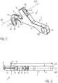
- the Figure 2 shows the transport hook 1 of the Figure 1 in a perspective view without the safety device 7.
- the through hole 10 is visible within a receptacle 6a for the securing device 7, and fastening points 11 in which the fastening plate 7a can be connected to the transport hook 1, for example, screwed or positively received via corresponding connecting elements not shown.
- the Figure 2 the through hole 8 for the safety rod 7c.
- the lever section 2 is designed as a flat body, i.e., it has two flat side walls 12 that run essentially parallel to each other.
- the side walls 12 can also run at an angle to each other, so that a thickness H ( Figure 3 ) and/or a width B of the lever section 2 changes.
- the lever section 2 has a first width B1 directly adjacent to its engagement section 15 and a second width B2 near the free end 2a, which is approximately twice as large as the width B1.
- the transition from the first width B1 to the second width B2 is stepped, but the widening of the lever section 2 over its length can also be continuous.
- the center of the coupling opening 4 can be slightly offset from a central longitudinal axis MLA ( Fig. 4a )) of the remaining lever section 2.
- the offset corresponds approximately to the radius of the coupling opening 4. Since the offset with respect to the central longitudinal axis MLA is directed towards the side on which the hook shank 3 is arranged, the angle ⁇ explained above between the connecting line V and the hook line HL is smaller than without offset, whereby the angling or engagement by the hook shank 3 is more pronounced.
- the Figure 3 shows the transport hook 1 of the Figure 2 in a plan view.
- the transport hook 1 of the exemplary embodiment has a substantially uniform thickness H over its entire length L. This means that a diameter D of the substantially round or circular hook shank 3 corresponds to the thickness of the flat lever section 2.
- the thickness H can also vary, for example, be smaller at the free end 2a than near the free securing end 3c.
- the transport hook 1 is related to a central longitudinal plane MLE (MLE is perpendicular to the plane of the drawing of Fig. 3 ) mirrored. This means that the transport hook 1 can consist of two cast or molded parts that are joined, for example, welded together. This allows the formation of the through holes 8 and 10 in the respective halves, thus eliminating the need for reworking of the transport hook 1.
- MLE central longitudinal plane
- the top view of the Figure 3 shows how the Figure 2 the through hole 8 for the safety rod 7c of the safety device 7, the through hole 10 and the fastening points 11.
- the Figure 4 includes a figure a) showing the transport hook 1 in a side view, a figure b) showing a further embodiment of the transport hook 1 with a free Securing end 3e on the hook shank 3, and a figure c) showing a section through the transport hook 1 of figure a) along the central longitudinal plane MLE and parallel to the side walls 12.
- the transport hook of figure c) comprises an optional magnet 19, in particular a permanent magnet, which additionally secures the transport hook 1 in the hole 102 if the load 101 consists of a magnetic metal or comprises a metal that is attracted by the magnet 19.
- the Figure 4a essentially corresponds to the illustration of the transport hook 1 in the Figure 1 , only without safety device 7. Therefore, please refer to the description of Figure 1 referred to.
- the Figure 4b shows an alternative embodiment of the transport hook 1.
- This transport hook 1 comprises a securing device in the form of a free securing end 3e, which is connected to the engagement section 3c.
- the free securing end 3e protrudes from the engagement section 3c in a direction away from the lever section 2 and extends in the longitudinal direction of the transport hook 1.
- the free securing end 3e and the engagement section 3c thus form a type of double nose, which reliably secures the transport hook 1 in the hole 102 of the load 101 when the transport hook 1 is not or not yet subjected to a tensile force by the transport device.
- the Figure 4c shows a section through the transport hook 1 of the Figure 4a without the securing device 7.
- the paths of the through-holes 8 and 10 within the hook shank 3 and the retaining tab 6 can be seen for the first time.
- the central axis A10 of the through-hole 10 and the central axis A8 of the through-hole 8 are aligned, i.e., the two central axes A8 and A10 coincide. This allows the through-holes 10 and 8 to be created in two work steps from one side, starting with the through-hole 10. It is also possible to drill the through-hole 10 and the through-hole 8 simultaneously with two tools from opposite sides.
- a magnet 14 is further connected to the transport hook 1, for example, glued on or connected by force and/or form fit.
- the magnet 14 forms an additional safeguard if the load 101 to be lifted consists of a magnetic material or comprises magnetic material, for example, metal particles in a reinforced plastic.
- the magnet 14 is preferably a permanent magnet, which Transport hook 1 is secured to the load 101 and which easily detaches from the load 101 when the load 101 is lifted at a preferably predefined weight force.
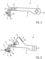
- the Figure 5 shows a transport lever 1 without a retaining tab 6 for connection to a securing device 7.
- the transport hook 1 comprises a securing element 5 in the region of the hook shank 3, which is connected to the engagement section 3c in the pivot joint S.
- the securing element 5 is elastically pretensioned into the illustrated securing position and can be pressed against the tensioning force, for example by hand, against the hook shank 3 in order to be inserted together with the hook shank 3 or the engagement section 3c into the hole 102 of a load 101.
- the securing element 5 Once the securing element 5 has been completely passed through the hole 102, it is automatically moved by the elastic force into the illustrated securing position and thereby secures the transport hook 1 in the hole 102 of the load 101.
- the Figure 6 shows a transport lever 1 with the securing device 7 and the securing element 5, which in this case is elastically pretensioned into a release position in which it rests against the hook shank 3. From this position, it can be moved by the securing device 7 against the elastic force into the illustrated securing position. To do this, the securing rod 7c presses with the free end 7d onto the securing element 5, moving it into the illustrated securing position and securing it in this position.
- the securing rod 7c can be secured in the position shown, for example by means of a locking mechanism (not shown) via the handle 9.
- the handle 9 can be rotated on the securing rod 7c to secure it in the telescopically extended position.
- the elastic restoring force acting on the securing element 5 can then press the securing element 5 back into the release position, whereby the securing rod 7c is simultaneously moved back into the through-hole 8 if the spring force of the securing element 5 is greater than the spring force applied to the securing rod 7c.
- the spring for loading the securing part 7b, 7c, 7e can be omitted entirely. This applies to all of the embodiments explained, since the securing part is then held in a defined position both in the locking position and in the release position without a spring. However, loading with a spring is advantageous, since the securing part always automatically assumes a specific position.
- the spring can also be arranged such that the securing part is pushed into the release position. In this case, however, a locking mechanism should be provided that can fix the securing part in the locking position.
- a transport hook 1 is formed with a movable safety lever 20 on the lever section 2 ( Fig. 9a, 9b ).
- the safety lever 20 is pivotally mounted by means of a pivot joint 21 adjacent to the coupling opening on the side of the lever section 2 from which the hook shank 3 also extends.
- the safety lever 20 can be folded away from the hook shank 3 until the safety lever strikes the hook shank with a stop element 22 and further pivoting movement is blocked ( Fig. 9b ).
- the safety lever 20 rests directly on the lever section 2.
- the transport hook 1 can thus be inserted into a hole 102 of a load 101 with the hook shank 3 and pulled out again, the lever section 2 being arranged approximately parallel to the surface of the load 101 for this purpose.
- the safety lever 20 protrudes from the lever section 2 on the same side as the hook shank 3 ( Fig. 9b ).
- the hook shank engages behind an edge on the hole 102 of a load 101.
- the lever section 2 cannot be brought close to the surface of the load 101, so that the transport hook 1 cannot be removed from the hole 102.
- the safety lever 20 thus forms a movable safety part on the transport hook 1, with which the transport hook can be secured at the hole 102.
- the safety lever can be secured in its end positions with a corresponding fixing device.
- This fixing device can, for example, comprise a spring which is arranged between the lever section 2 and the safety lever 20. is arranged and presses them apart.
- a fixing ring can wrap around the lever section 2 and be moved along the lever section so that it also encloses the safety lever 20 resting against the lever section 2 and holds it in its position resting against the lever section 2 ( Fig. 9a ).
- locking means can be provided which lock the safety lever in its end positions according to Fig. 9a and/or Fig. 9b
- another movable safety part that is not pivotable can also be provided, which can form a projection that can be changed from the lever section 2.
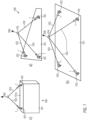
- the Figure 7 shows in the sketch a) by way of example a first lifting system 100, which carries a plate-shaped load 101 or a structure with a plate-shaped section.
- the load 101 comprises three essentially circular holes 102 with a diameter slightly larger than the diameter D of the hook shank 3 ( Figure 3 ) of the transport hooks 1, which pass through the holes 102 of the load 101.
- the transport hooks 1 can be connected via ropes or chains 103 to a lifting device 200, which is shown as a directional arrow in sketch a).
- the ropes 103 can be connected to the lifting device 200, for example, a crane, directly or via a connecting element 104.
- Sketch b) shows a second lifting system 100 that supports a plate-shaped load 101 or a structure with a plate-shaped section.
- the structure 101 comprises four essentially circular holes 102 with a diameter slightly larger than the diameter D of the hook shank 3 ( Figure 3 ) of the transport hooks 1, which pass through the holes 102 of the load 101.
- the transport hooks 1 can be connected via ropes or chains 103 to a lifting device 200, which is shown as a directional arrow in sketch b).
- the ropes 103 can be connected to the lifting device 200, for example, a crane, directly or via a connecting element 104.
- Sketch c) shows a lifting system 100 with a load 101 in the form of a box or a hollow body.
- Two holes 102 are provided in the top side 101 of the load 101, which forms a plate-shaped section, into which transport hooks 1 engage.
- the transport hooks 1 are, as shown in sketches a) and b), Figure 7 connected to a lifting device 200 via ropes 103.
- Sketch a shows the transport hook 1 with the lever section 2 and the hook shank 3, as it is, for example, manually guided to the circular hole 102 of the load 101.
- sketch b shows the hook shank 3 is guided through the circular hole 102 of the load 101 and protrudes downwards from the plate-shaped load 101.
- the lever section 2 of the transport hook 1 lies essentially flat on the upper side 101a of the load 101.
- the transport hook 1 is connected via the coupling opening 4 to a lifting device 200, which is shown in the sketch c) as a directional arrow, for example a crane, and the transport hook 1 is subjected to a tensile force, whereby the transport hook 1 rotates in the hole 102 of the load 101 about a lower edge of the inner circumferential wall 104 and the hook shank 3 is pivoted towards a bottom side 101b of the load 101.
- the position shown in the sketch c) is the final position of the transport hook 1 when the load 101 is lifted with one of the lifting systems 100 of the Figure 7 with several holes 102 and several transport hooks 1.
- the straight line V which connects the point of application of the lifting device 200 on the lever section with the vertex SP of the angle section 14.
- the angle ⁇ between the straight line V and a second straight line on the upper side of the hook shank is less than 90°.
- the single transport hook 1 has been moved by the lifting device 200, which is shown in sketch d) as a directional arrow, into a final position in which the transport hook 1 supports the weight of the load 101.
- the load 101 hangs essentially vertically downwards from the transport hook.
- the plate-shaped section of the load 101 having the hole 102 is thin compared to the hook shank 3.
- a thin load 101 which means that it is thin in the area of the hole 102 compared to the thickness of the hook shank 3, it is sufficient if the hole 102 is only slightly larger than the cross-sectional area or the maximum diameter D of the hook shank 3.
- the maximum hole diameter should preferably not be larger than twice the maximum diameter D of the hook shank 3, in particular not larger than 1.8 times the maximum diameter D of the hook shank 3 or not larger than 1.5 times the maximum diameter D of the hook shank 3 or not larger than 1.3 times the maximum diameter D of the hook shank 3, so that the hook shank and the angle section can be inserted into the hole on the one hand and cannot escape on the other hand when the transport hook is under tension during lifting.
- the thickness of the load in the region of the hole 102 is preferably not greater than 2 times the maximum diameter D of the hook shank 3, in particular not greater than 1.5 times the maximum diameter D of the hook shank 3 or not greater than 1.3 times the maximum diameter D of the hook shank 3.
- the maximum hole diameter should be smaller than one hook shank length HSL (Fig. 3 a)), which is the distance between the free end 3b of the hook shank and the side of the lever section 2 remote from the hook shank 3.
- the maximum diameter of the hole is preferably smaller than 0.8 times the hook shank length HSL, in particular smaller than 0.7 times the hook shank length HSL or smaller than 0.5 times the hook shank length HSL or smaller than 0.3 times the hook shank length HSL. This limits the maximum thickness of the load in the area of the hole.
- the hole 102 is preferably circular. It may also deviate from the circular shape, whereby it is expedient that the smallest hole diameter is different from the largest hole diameter. does not deviate by more than 50%, preferably not more than 25% and in particular not more than 10%.
- the Figures 10a - 10c show the transport hook 1 of the Figure 1 in a modified form.
- the transport hook 1 comprises the lever section 2 with the coupling opening 4 and the hook shank 3, which can pass through a hole 102 of a load 101 (both not shown) in order to lift and transport the load 101 by means of a lifting system 100 (not shown).
- the transport hook 1 comprises a securing device with which it can be secured in the hole 102 or is secured when the transport hook 1 is subjected to a tensile force by the lifting system 100, so that the transport hook 1 cannot be inadvertently moved out of the hole 102 when the securing device is active.
- the transport hook 1 comprises a wing element 18, which can consist of two separate wings 18.1 and 18.2.
- the wing element 18 is connected to the transport hook 1 on an underside 2b of the transport hook 1 facing the hook shank 3, preferably firmly connected by means of adhesion, material or force fit, etc.
- the wings 18.1 and 18.2 are in a plan view of the transport hook 1, as shown in FIG. Figure 10a ) shows, to the side of the transport hook 1.
- the transport hook 1 has a diameter D in the area in which the wing element 18 or the wings 18.1, 18.6 is/are connected to the transport hook 1 (see Figure 2 ).
- the distance AFF between the outer ends 18.1a, 18.2a, i.e., those pointing away from the transport hook 1, can then, for example, correspond approximately to twice the diameter D of the transport hook 1 in this area.
- the distance AFF can also be larger or smaller.
- the distance AFF can also be referred to as the span of the wing element 18.
- the wing element 18 can, in the state connected to the transport hook 1, protrude below the lower surface 2b of the lever section 2 or of the transport hook 1 in the vicinity of the connection area with the wing element 18, as shown, or be arranged in a recess not explicitly shown, so that the wing element 18 does not protrude beyond the underside of the transport hook 1, but is preferably flat with the surrounding surface of the transport hook 1.
- the transport hook 1 further comprises a nose 23, which is formed on an upper side of the transport hook 1.
- the nose 23 is in the illustrated embodiment dormer-shaped from the upper side 2c facing away from the hook leg 3.
- the nose 23 has a flat front side 23a facing the retaining tab 6, which in the illustrated embodiment runs essentially parallel to the outer surface 6b of the retaining tab 6 facing the nose 23.
- the nose 23 is connected to the transport hook 1 in the area in which an opening of the through-bore 8 is located, which forms an opening and guide for the securing rod 7c in the angled section 14.
- the nose 23 extends the through-bore 23, and the front side 23a advantageously forms a flat mounting surface for a drill for creating the through-bore 8 in the angled section 14 of the transport hook 1.
- the nose extends the guide area for the securing rod 7c, and the securing rod 7c is better protected in the extended through-bore 8.
- the upper side of the nose 23 can run parallel to a central longitudinal axis (not shown) of the securing rod 7c.
- the height HN of the nose 23 in the area of the front side 23a, perpendicular to the central axis of the securing rod 7c, can be selected such that the nose 23 completely covers the handle 9 when viewed from the front onto the transport hook 1. This prevents the handle 9 from being accidentally released from the shown securing position when the load is being gripped or transported.
- the last-described nose 23 reliably prevents, for example, a cable of the lifting system 100 or an unevenness of the load 101 from accidentally moving the handle, thus jeopardizing the safety of the transport.
- the nose 23 can have a distance NT from a tangent T, which rests on the surface of a frontmost end of the transport hook 1, which distance depends on the diameter D of the hook shank 3 and/or the angled section 14.
- the distance NT can preferably be approximately twice the diameter D. However, the distance NT can also be smaller or larger than twice the diameter.
- the height HN of the front side 23a can be determined by an extension part 24, which is part of the nose 23 and is formed together with the nose 23 or is formed separately from the nose 23 and subsequently connected to the nose 23.
- the extension part 24 can be made of a material different from the material of the nose 23 made of a different material, such as plastic, and can be replaced if it becomes worn or damaged.
- the nose 23 can also comprise a securing element with which the securing rod 7c can be secured in the securing position and preferably also in the rest position.
- This securing element can be, for example, a slider that engages or snaps into recesses on the securing rod 7c.
- the extension 24 can form the securing element.
- Other known mechanisms for securing the securing rod 7c in fixed positions relative to the through-bore 8 are encompassed by the invention. With such a solution, the retaining tab 6 can be omitted entirely, which leads to material and cost savings.
- Figure 10b shows an embodiment in which the handle 9 forms the end of the safety rod 7c.
- the retaining tab 6 can be plate-shaped, with a thickness in the longitudinal direction of the transport hook 1 which is considerably smaller than in the Figure 10b shown, for example a steel plate with a thickness of 3 mm or 0.5 cm or 1 cm or another dimension.
- the spring element (not shown) which pretensions the securing rod 7c into the securing position or the rest position would lie outside the retaining tab 6 and be supported with one end on an outer side of the retaining tab and with the other end on the handle.
- the spring is preferably a helical spring which encloses the securing rod 7c.
- no fastening plate 7a as provided in the exemplary embodiments explained above, is necessary.
- the spring element can be protected against contamination by an elastic sheath.
Landscapes
- Engineering & Computer Science (AREA)
- Mechanical Engineering (AREA)
- Hooks, Suction Cups, And Attachment By Adhesive Means (AREA)
- Forklifts And Lifting Vehicles (AREA)
- Materials For Medical Uses (AREA)
- Load-Engaging Elements For Cranes (AREA)
Claims (15)
- Crochet de transport (1) pour soulever et déplacer une charge (101),le crochet de transport (1) comprenant une section de levier (2) ayant un élément de couplage (4) permettant de relier le crochet de transport (1) à un dispositif de levage, et une branche de crochet (3) pouvant traverser un trou (102) de la charge (101),la branche de crochet (3) étant reliée à la section de levier (2) par une section angulaire (14),un dispositif de sécurité étant prévu, comprenant une pièce de sécurité (7b, 7c, 7e) disposée de manière mobile sur le crochet de transport (1) de sorte qu'elle puisse former une saillie de sorte qu'une branche de crochet (3) passée à travers le trou (102) ne puisse plus s'échapper du trou (102),caractérisé en ce quela saillie peut être formée sur la branche du crochet,en ce que la pièce de sécurité (7b, 7c, 7e) comprend une tige de sécurité (7c) qui est montée sur le crochet de transport (1) de manière à pouvoir coulisser dans la direction longitudinale, eten ce que la section angulaire (14) comprend un trou traversant (8) formant un guidage pour la pièce de sécurité (7b, 7c, 7e).
- Le crochet de transport (1) selon la revendication 1, sachant que la branche de crochet (3) est reliée à la section de levier (2) par la section angulaire (14) de telle sorte qu'un angle (α) soit formé entre une ligne (L) s'étendant de l'élément de couplage (4) à un sommet (SP) situé sur la surface intérieure de la section angulaire (14) et une ligne (HL) s'étendant le long de la branche de crochet (3), qui est inférieur à 90°,
sachant que la branche de crochet (3) et la section angulaire (14) forment un cordon continu d'épaisseur quasi uniforme, de sorte que, pour soulever et déplacer la charge (101), la branche de crochet (3) et la section angulaire (14) s'engagent dans le trou (102) de la charge (101) et que la branche de crochet (3) ou la section angulaire (14) puisse passer derrière un bord du trou (102). - Le crochet de transport (1) selon la revendication 1 ou 2, sachant qu'au moins la branche de crochet (3) est un corps rond avec une section transversale essentiellement ronde.
- Le crochet de transport (1) selon l'une quelconque des revendications 1 à 3, sachant que l'élément de couplage est réalisé sous forme d'une ouverture de couplage (4) au niveau de la section de levier (2) et/ou que l'élément de couplage (4) est disposé à l'extrémité libre (2a) de la section de levier (2) opposée à la branche de crochet (3).
- Le crochet de transport (1) selon l'une quelconque des revendications 1 à 4, sachant que le crochet de transport (1) est formé d'une seule pièce, par exemple moulé, pressé à partir d'une poudre, usiné à partir d'un matériau plein ou forgé à partir d'un produit semi-fini,
et/ou
sachant que la section de levier (2) est en forme de plaque, avec une longueur (L) plusieurs fois supérieure à une largeur (B) ou une épaisseur (H) de la section de levier (2). - Le crochet de transport (1) selon l'une quelconque des revendications 1 à 5, sachant que la branche de crochet (3) est reliée à la section de levier (2) par la section angulaire (14), ladite section de levier étant formée de manière adjacente à la section angulaire (14) avec une zone d'engagement (15), et sachant que la zone d'engagement (15), la section angulaire (14) et la branche de crochet (3) sont chacune formées comme un corps rond avec une section transversale sensiblement ronde.
- Le crochet de transport (1) selon la revendication 6, sachant que les diamètres (D) de la zone d'engagement (15), de la section angulaire (14) et de la branche de crochet (3) sont sensiblement identiques et correspondent notamment à l'épaisseur (H) de la section de levier en forme de plaque (2).
- Le crochet de transport (1) selon l'une quelconque des revendications 1 à 7, sachant qu'une largeur (B) de la section de levier (2), à une extrémité libre (2a) opposée à la branche de crochet (3), est supérieure à une largeur (B) de la section de levier (2) adjacente à la branche de crochet (3),
et/ou que
la section de levier (2) est plusieurs fois plus longue que la section d'engagement (3c) de la branche de crochet (3). - Le crochet de transport (1) selon l'une quelconque des revendications 1 à 8, sachant que la pièce de sécurité (7b, 7c, 7e) est sollicitée par un ressort, de sorte qu'elle peut être déplacée à l'encontre de l'action du ressort de telle sorte qu'elle ne forme pas de saillie sur la branche de crochet (3) et que celle-ci peut être retirée du trou (102).
- Le crochet de transport (1) selon l'une quelconque des revendications 1 à 9, sachant que la section de levier (2) comprend une patte de retenue (6) conçue pour retenir le dispositif de sécurité (7).
- Le crochet de transport (1) selon l'une quelconque des revendications 1 à 10, sachant que la section de sécurité (7b, 7c, 7e) comprend une poignée (9) pour actionner la section de sécurité (7b, 7c, 7e), la poignée (9) pouvant également être configurée comme une butée pour fixer l'une ou les deux positions extrêmes de la section de sécurité mobile (7b, 7c, 7e).
- Le crochet de transport (1) selon l'une quelconque des revendications 1 à 11, sachant qu'un mécanisme d'encliquetage est prévu pour fixer de manière amovible la pièce de sécurité mobile (7b, 7c, 7e) dans l'une de ses positions extrêmes.
- Le crochet de transport (1) selon l'une quelconque des revendications 1 à 12, sachant que le crochet de transport (1) comprend un élément de blocage (5) qui bloque le crochet de transport (1) dans le trou (102) de la charge (101).
- Le crochet de transport (1) selon la revendication 13, sachant que l'élément de blocage (5) est relié à la branche de crochet (3) par une articulation pivotante (S) et est de préférence précontraint élastiquement dans une position de sécurité dans laquelle il s'écarte de la branche de crochet (3) ou dans une position dans laquelle il est en contact avec la branche de crochet (3).
- Le crochet de transport (1) selon la revendication 13 ou 14, sachant que l'élément de blocage (5) peut être appliqué contre une surface de la branche de crochet (3) lors du passage de la section d'engagement (3c) à travers le trou (102) de la charge (101) et pivote élastiquement dans la position de sécurité après le passage à travers le trou (102).
Applications Claiming Priority (3)
| Application Number | Priority Date | Filing Date | Title |
|---|---|---|---|
| ATA50294/2020A AT523664B1 (de) | 2020-04-06 | 2020-04-06 | Transporthaken |
| DE102020123514 | 2020-09-09 | ||
| PCT/EP2021/058668 WO2021204688A1 (fr) | 2020-04-06 | 2021-04-01 | Crochet de transport |
Publications (3)
| Publication Number | Publication Date |
|---|---|
| EP4132874A1 EP4132874A1 (fr) | 2023-02-15 |
| EP4132874B1 true EP4132874B1 (fr) | 2025-05-07 |
| EP4132874C0 EP4132874C0 (fr) | 2025-05-07 |
Family
ID=75377808
Family Applications (1)
| Application Number | Title | Priority Date | Filing Date |
|---|---|---|---|
| EP21716397.1A Active EP4132874B1 (fr) | 2020-04-06 | 2021-04-01 | Crochet de transport |
Country Status (7)
| Country | Link |
|---|---|
| US (1) | US20230174348A1 (fr) |
| EP (1) | EP4132874B1 (fr) |
| JP (1) | JP2023520738A (fr) |
| CN (1) | CN115485225A (fr) |
| AU (1) | AU2021252089A1 (fr) |
| CA (1) | CA3178866A1 (fr) |
| WO (1) | WO2021204688A1 (fr) |
Family Cites Families (24)
| Publication number | Priority date | Publication date | Assignee | Title |
|---|---|---|---|---|
| US845724A (en) | 1906-05-17 | 1907-02-26 | Frank E Whidden | Lewis. |
| US1373438A (en) | 1920-06-22 | 1921-04-05 | Mcdowell John | Self-locking lifting device |
| US3450428A (en) * | 1967-07-31 | 1969-06-17 | Delbert W Zimmermann | Device for handling workpieces |
| US3652116A (en) * | 1970-05-25 | 1972-03-28 | Dana L Pruitt | Lift chain connector |
| USRE28709E (en) * | 1971-07-30 | 1976-02-10 | American Hoist & Derrick Company | Safety hook |
| US3915487A (en) * | 1974-09-05 | 1975-10-28 | Teledyne Inc | Stabilized coupling link for chain and hook assembly |
| US4148514A (en) * | 1975-06-30 | 1979-04-10 | The United States Of America As Represented By The Secretary Of The Navy | Tension release latch |
| DE2704732C3 (de) * | 1977-02-04 | 1980-01-10 | Windmoeller & Hoelscher, 4540 Lengerich | Tragbügel für gefüllte Säcke |
| US4171842A (en) * | 1978-01-27 | 1979-10-23 | Tolle Manufacturing Co., Inc. | J-hook |
| US4326744A (en) * | 1979-03-07 | 1982-04-27 | Kennecott Corporation | Work hook device |
| US4248469A (en) * | 1979-07-10 | 1981-02-03 | Knox Norman C | Lifting harness |
| JPS5932396B2 (ja) * | 1980-09-20 | 1984-08-08 | 日本鉄板リ−ス株式会社 | 敷鉄板のハンドリング方法 |
| JPS6019099Y2 (ja) * | 1981-02-28 | 1985-06-08 | 清水建設株式会社 | 吊り金具 |
| US4613180A (en) * | 1984-12-17 | 1986-09-23 | Pope Ralph D | Quick-release device |
| US4669618A (en) * | 1985-11-18 | 1987-06-02 | Outboard Marine Corporation | Lifting assembly |
| JPH01132686U (fr) * | 1988-03-01 | 1989-09-08 | ||
| FR2677969B1 (fr) * | 1991-06-21 | 1997-04-18 | Aerospatiale | Dispositif d'accrochage d'une charge a manutentionner sur une elingue de levage. |
| US5997063A (en) * | 1998-03-04 | 1999-12-07 | Columbus Mckinnon | J-hook with shank portion having oval-shaped transverse cross-section |
| NO327971B1 (no) * | 2004-08-27 | 2009-11-02 | Jack Ivan Braten | Anordning ved loftekrok |
| US7473063B1 (en) * | 2006-01-20 | 2009-01-06 | Adams Bill J | Trailer strap bracket system |
| US20080292397A1 (en) | 2007-05-10 | 2008-11-27 | Farney Greg | Ground covering support structure |
| US20100207410A1 (en) * | 2009-02-19 | 2010-08-19 | Life-Pack Technologies, Inc. | Opposed Spring-Loaded Anchor Hook Supporting Device |
| US9741847B2 (en) | 2015-11-30 | 2017-08-22 | Globalfoundries Inc. | Methods of forming a contact structure for a vertical channel semiconductor device and the resulting device |
| DE102016222787A1 (de) | 2016-11-18 | 2018-05-24 | Robert Bosch Gmbh | Transporthaken mit Sicherung |
-
2021
- 2021-04-01 US US17/917,275 patent/US20230174348A1/en active Pending
- 2021-04-01 JP JP2023503515A patent/JP2023520738A/ja active Pending
- 2021-04-01 EP EP21716397.1A patent/EP4132874B1/fr active Active
- 2021-04-01 WO PCT/EP2021/058668 patent/WO2021204688A1/fr not_active Ceased
- 2021-04-01 AU AU2021252089A patent/AU2021252089A1/en not_active Abandoned
- 2021-04-01 CN CN202180031359.3A patent/CN115485225A/zh active Pending
- 2021-04-01 CA CA3178866A patent/CA3178866A1/fr active Pending
Also Published As
| Publication number | Publication date |
|---|---|
| CA3178866A1 (fr) | 2021-10-14 |
| WO2021204688A1 (fr) | 2021-10-14 |
| JP2023520738A (ja) | 2023-05-18 |
| CN115485225A (zh) | 2022-12-16 |
| EP4132874A1 (fr) | 2023-02-15 |
| AU2021252089A1 (en) | 2022-11-10 |
| EP4132874C0 (fr) | 2025-05-07 |
| AU2021252089A2 (en) | 2022-12-22 |
| US20230174348A1 (en) | 2023-06-08 |
Similar Documents
| Publication | Publication Date | Title |
|---|---|---|
| DE102018103897A1 (de) | Gerüst mit einer Aushebesicherungsvorrichtung und Verfahren zur Sicherung eines Gerüstbodens gegen Ausheben | |
| DE202010003033U1 (de) | Hebezeug zur Positionierung eines Rotorblatts einer Windenergieanlage | |
| EP2607290B1 (fr) | Bascule pour suspension avec dispositif d'affichage | |
| DE2119951B2 (de) | Scharnierhebeklaue | |
| DE60311129T2 (de) | Verriegelungsmittel für einen spannverschluss | |
| DE10100993A1 (de) | Einrichtung zum Verstellen einer Länge eines als Endlosschlinge ausgebildeten Anschlagmittels und Vorrichtung zum Heben von Lasten | |
| EP1939132A2 (fr) | Cintre ou crochet de charge pouvant être actionné à distance | |
| DE102016205836A1 (de) | Haken zum Versetzen von Schalungselementen | |
| DE29623539U1 (de) | Hebeverbindungsvorrichtung | |
| EP4132874B1 (fr) | Crochet de transport | |
| EP3299332B1 (fr) | Patte d'arrêt ou d'arrimage, support de fixation pour une patte d'arrêt ou d'arrimage ainsi que point d'arrêt ou d'arrimage pourvue d'une patte d'arrêt ou d'arrimage et support de fixation | |
| DE102012108486A1 (de) | Lastaufnahmevorrichtung, insbesondere Unterflasche für ein Hebezeug | |
| AT523664B1 (de) | Transporthaken | |
| DE1481800B1 (de) | Hebeklaue | |
| DE202019103087U1 (de) | Transportvorrichtung mit translatorisch beweglichem Verstellelement | |
| EP3246202B1 (fr) | Point d'ancrage | |
| DE60027948T2 (de) | Vorrichtung zur Sicherung von Lasten | |
| DE2044502C3 (de) | Verbindungshaken | |
| WO2012062865A1 (fr) | Moyen d'amarrage et dispositif comprenant un tel moyen d'amarrage pour le levage de charges lourdes | |
| DE2617866C3 (de) | Aiischlagvorrichtung für Betonfertigteile | |
| DE19502225C2 (de) | Anhängevorrichtung zum Anhängen wenigstens einer Schaltafel an ein Hebezeug | |
| EP2408706A1 (fr) | Élément de butée et combinaison d'un élément de butée et d'un moyen de fixation | |
| DE3712227A1 (de) | Seilsicherung fuer ein bergsteiger-kletterseil | |
| DE1456464B2 (de) | Selbsttätige Verriegelungseinrichtung für Tragschlingen, insbesondere Sacktragschiingen | |
| DE102016116773B4 (de) | Nocken und Einrichtung zum Anschlagen eines Spann- oder Anschlagmittels an einem Untergrund sowie Boden oder Wand für ein Nutzfahrzeug mit einer Einrichtung zum Anschlagen eines Spann- oder Anschlagmittels |
Legal Events
| Date | Code | Title | Description |
|---|---|---|---|
| STAA | Information on the status of an ep patent application or granted ep patent |
Free format text: STATUS: UNKNOWN |
|
| STAA | Information on the status of an ep patent application or granted ep patent |
Free format text: STATUS: THE INTERNATIONAL PUBLICATION HAS BEEN MADE |
|
| PUAI | Public reference made under article 153(3) epc to a published international application that has entered the european phase |
Free format text: ORIGINAL CODE: 0009012 |
|
| STAA | Information on the status of an ep patent application or granted ep patent |
Free format text: STATUS: REQUEST FOR EXAMINATION WAS MADE |
|
| 17P | Request for examination filed |
Effective date: 20221107 |
|
| AK | Designated contracting states |
Kind code of ref document: A1 Designated state(s): AL AT BE BG CH CY CZ DE DK EE ES FI FR GB GR HR HU IE IS IT LI LT LU LV MC MK MT NL NO PL PT RO RS SE SI SK SM TR |
|
| DAV | Request for validation of the european patent (deleted) | ||
| DAX | Request for extension of the european patent (deleted) | ||
| REG | Reference to a national code |
Ref country code: DE Free format text: PREVIOUS MAIN CLASS: B66C0001360000 Ipc: B66C0001140000 Ref country code: DE Ref legal event code: R079 Ref document number: 502021007409 Country of ref document: DE Free format text: PREVIOUS MAIN CLASS: B66C0001360000 Ipc: B66C0001140000 |
|
| GRAP | Despatch of communication of intention to grant a patent |
Free format text: ORIGINAL CODE: EPIDOSNIGR1 |
|
| STAA | Information on the status of an ep patent application or granted ep patent |
Free format text: STATUS: GRANT OF PATENT IS INTENDED |
|
| RIC1 | Information provided on ipc code assigned before grant |
Ipc: B66C 1/66 20060101ALI20241122BHEP Ipc: B66C 1/36 20060101ALI20241122BHEP Ipc: B66C 1/14 20060101AFI20241122BHEP |
|
| INTG | Intention to grant announced |
Effective date: 20241211 |
|
| GRAS | Grant fee paid |
Free format text: ORIGINAL CODE: EPIDOSNIGR3 |
|
| GRAA | (expected) grant |
Free format text: ORIGINAL CODE: 0009210 |
|
| STAA | Information on the status of an ep patent application or granted ep patent |
Free format text: STATUS: THE PATENT HAS BEEN GRANTED |
|
| AK | Designated contracting states |
Kind code of ref document: B1 Designated state(s): AL AT BE BG CH CY CZ DE DK EE ES FI FR GB GR HR HU IE IS IT LI LT LU LV MC MK MT NL NO PL PT RO RS SE SI SK SM TR |
|
| REG | Reference to a national code |
Ref country code: GB Ref legal event code: FG4D Free format text: NOT ENGLISH |
|
| REG | Reference to a national code |
Ref country code: CH Ref legal event code: EP |
|
| REG | Reference to a national code |
Ref country code: DE Ref legal event code: R096 Ref document number: 502021007409 Country of ref document: DE |
|
| REG | Reference to a national code |
Ref country code: IE Ref legal event code: FG4D Free format text: LANGUAGE OF EP DOCUMENT: GERMAN |
|
| U01 | Request for unitary effect filed |
Effective date: 20250603 |
|
| U07 | Unitary effect registered |
Designated state(s): AT BE BG DE DK EE FI FR IT LT LU LV MT NL PT RO SE SI Effective date: 20250610 |
|
| PG25 | Lapsed in a contracting state [announced via postgrant information from national office to epo] |
Ref country code: ES Free format text: LAPSE BECAUSE OF FAILURE TO SUBMIT A TRANSLATION OF THE DESCRIPTION OR TO PAY THE FEE WITHIN THE PRESCRIBED TIME-LIMIT Effective date: 20250507 |
|
| PG25 | Lapsed in a contracting state [announced via postgrant information from national office to epo] |
Ref country code: GR Free format text: LAPSE BECAUSE OF FAILURE TO SUBMIT A TRANSLATION OF THE DESCRIPTION OR TO PAY THE FEE WITHIN THE PRESCRIBED TIME-LIMIT Effective date: 20250808 Ref country code: NO Free format text: LAPSE BECAUSE OF FAILURE TO SUBMIT A TRANSLATION OF THE DESCRIPTION OR TO PAY THE FEE WITHIN THE PRESCRIBED TIME-LIMIT Effective date: 20250807 |
|
| PG25 | Lapsed in a contracting state [announced via postgrant information from national office to epo] |
Ref country code: PL Free format text: LAPSE BECAUSE OF FAILURE TO SUBMIT A TRANSLATION OF THE DESCRIPTION OR TO PAY THE FEE WITHIN THE PRESCRIBED TIME-LIMIT Effective date: 20250507 |
|
| PG25 | Lapsed in a contracting state [announced via postgrant information from national office to epo] |
Ref country code: HR Free format text: LAPSE BECAUSE OF FAILURE TO SUBMIT A TRANSLATION OF THE DESCRIPTION OR TO PAY THE FEE WITHIN THE PRESCRIBED TIME-LIMIT Effective date: 20250507 |
|
| PG25 | Lapsed in a contracting state [announced via postgrant information from national office to epo] |
Ref country code: RS Free format text: LAPSE BECAUSE OF FAILURE TO SUBMIT A TRANSLATION OF THE DESCRIPTION OR TO PAY THE FEE WITHIN THE PRESCRIBED TIME-LIMIT Effective date: 20250807 |
|
| PG25 | Lapsed in a contracting state [announced via postgrant information from national office to epo] |
Ref country code: IS Free format text: LAPSE BECAUSE OF FAILURE TO SUBMIT A TRANSLATION OF THE DESCRIPTION OR TO PAY THE FEE WITHIN THE PRESCRIBED TIME-LIMIT Effective date: 20250907 |
|
| PG25 | Lapsed in a contracting state [announced via postgrant information from national office to epo] |
Ref country code: SM Free format text: LAPSE BECAUSE OF FAILURE TO SUBMIT A TRANSLATION OF THE DESCRIPTION OR TO PAY THE FEE WITHIN THE PRESCRIBED TIME-LIMIT Effective date: 20250507 |
|
| PG25 | Lapsed in a contracting state [announced via postgrant information from national office to epo] |
Ref country code: CZ Free format text: LAPSE BECAUSE OF FAILURE TO SUBMIT A TRANSLATION OF THE DESCRIPTION OR TO PAY THE FEE WITHIN THE PRESCRIBED TIME-LIMIT Effective date: 20250507 |
|
| PG25 | Lapsed in a contracting state [announced via postgrant information from national office to epo] |
Ref country code: SK Free format text: LAPSE BECAUSE OF FAILURE TO SUBMIT A TRANSLATION OF THE DESCRIPTION OR TO PAY THE FEE WITHIN THE PRESCRIBED TIME-LIMIT Effective date: 20250507 |
|
| PLBE | No opposition filed within time limit |
Free format text: ORIGINAL CODE: 0009261 |
|
| STAA | Information on the status of an ep patent application or granted ep patent |
Free format text: STATUS: NO OPPOSITION FILED WITHIN TIME LIMIT |
|
| REG | Reference to a national code |
Ref country code: CH Ref legal event code: L10 Free format text: ST27 STATUS EVENT CODE: U-0-0-L10-L00 (AS PROVIDED BY THE NATIONAL OFFICE) Effective date: 20260318 |
|
| 26N | No opposition filed |
Effective date: 20260210 |
|
| U20 | Renewal fee for the european patent with unitary effect paid |
Year of fee payment: 6 Effective date: 20260320 |