EP3246437A1 - Dispositif de blocage d'une petite bande fibrillee - Google Patents
Dispositif de blocage d'une petite bande fibrillee Download PDFInfo
- Publication number
- EP3246437A1 EP3246437A1 EP16170505.8A EP16170505A EP3246437A1 EP 3246437 A1 EP3246437 A1 EP 3246437A1 EP 16170505 A EP16170505 A EP 16170505A EP 3246437 A1 EP3246437 A1 EP 3246437A1
- Authority
- EP
- European Patent Office
- Prior art keywords
- deflection
- hollow shaft
- ribbon
- fibrillated
- rotation
- Prior art date
- Legal status (The legal status is an assumption and is not a legal conclusion. Google has not performed a legal analysis and makes no representation as to the accuracy of the status listed.)
- Granted
Links
Images

Classifications
-
- D—TEXTILES; PAPER
- D01—NATURAL OR MAN-MADE THREADS OR FIBRES; SPINNING
- D01D—MECHANICAL METHODS OR APPARATUS IN THE MANUFACTURE OF ARTIFICIAL FILAMENTS, THREADS, FIBRES, BRISTLES OR RIBBONS
- D01D5/00—Formation of filaments, threads, or the like
- D01D5/08—Melt spinning methods
-
- D—TEXTILES; PAPER
- D01—NATURAL OR MAN-MADE THREADS OR FIBRES; SPINNING
- D01H—SPINNING OR TWISTING
- D01H7/00—Spinning or twisting arrangements
- D01H7/02—Spinning or twisting arrangements for imparting permanent twist
- D01H7/86—Multiple-twist arrangements, e.g. two-for-one twisting devices ; Threading of yarn; Devices in hollow spindles for imparting false twist
- D01H7/868—Yarn guiding means, e.g. guiding tubes
-
- B—PERFORMING OPERATIONS; TRANSPORTING
- B29—WORKING OF PLASTICS; WORKING OF SUBSTANCES IN A PLASTIC STATE IN GENERAL
- B29C—SHAPING OR JOINING OF PLASTICS; SHAPING OF MATERIAL IN A PLASTIC STATE, NOT OTHERWISE PROVIDED FOR; AFTER-TREATMENT OF THE SHAPED PRODUCTS, e.g. REPAIRING
- B29C48/00—Extrusion moulding, i.e. expressing the moulding material through a die or nozzle which imparts the desired form; Apparatus therefor
- B29C48/001—Combinations of extrusion moulding with other shaping operations
- B29C48/0019—Combinations of extrusion moulding with other shaping operations combined with shaping by flattening, folding or bending
-
- B—PERFORMING OPERATIONS; TRANSPORTING
- B29—WORKING OF PLASTICS; WORKING OF SUBSTANCES IN A PLASTIC STATE IN GENERAL
- B29C—SHAPING OR JOINING OF PLASTICS; SHAPING OF MATERIAL IN A PLASTIC STATE, NOT OTHERWISE PROVIDED FOR; AFTER-TREATMENT OF THE SHAPED PRODUCTS, e.g. REPAIRING
- B29C48/00—Extrusion moulding, i.e. expressing the moulding material through a die or nozzle which imparts the desired form; Apparatus therefor
- B29C48/001—Combinations of extrusion moulding with other shaping operations
- B29C48/0022—Combinations of extrusion moulding with other shaping operations combined with cutting
-
- D—TEXTILES; PAPER
- D02—YARNS; MECHANICAL FINISHING OF YARNS OR ROPES; WARPING OR BEAMING
- D02G—CRIMPING OR CURLING FIBRES, FILAMENTS, THREADS, OR YARNS; YARNS OR THREADS
- D02G3/00—Yarns or threads, e.g. fancy yarns; Processes or apparatus for the production thereof, not otherwise provided for
- D02G3/22—Yarns or threads characterised by constructional features, e.g. blending, filament/fibre
- D02G3/38—Threads in which fibres, filaments, or yarns are wound with other yarns or filaments, e.g. wrap yarns, i.e. strands of filaments or staple fibres are wrapped by a helically wound binder yarn
- D02G3/385—Threads in which fibres, filaments, or yarns are wound with other yarns or filaments, e.g. wrap yarns, i.e. strands of filaments or staple fibres are wrapped by a helically wound binder yarn using hollow spindles, e.g. making coverspun yarns
-
- E—FIXED CONSTRUCTIONS
- E01—CONSTRUCTION OF ROADS, RAILWAYS, OR BRIDGES
- E01C—CONSTRUCTION OF, OR SURFACES FOR, ROADS, SPORTS GROUNDS, OR THE LIKE; MACHINES OR AUXILIARY TOOLS FOR CONSTRUCTION OR REPAIR
- E01C13/00—Pavings or foundations specially adapted for playgrounds or sports grounds; Drainage, irrigation or heating of sports grounds
- E01C13/08—Surfaces simulating grass ; Grass-grown sports grounds
-
- D—TEXTILES; PAPER
- D10—INDEXING SCHEME ASSOCIATED WITH SUBLASSES OF SECTION D, RELATING TO TEXTILES
- D10B—INDEXING SCHEME ASSOCIATED WITH SUBLASSES OF SECTION D, RELATING TO TEXTILES
- D10B2505/00—Industrial
- D10B2505/20—Industrial for civil engineering, e.g. geotextiles
- D10B2505/202—Artificial grass
Definitions
- the invention relates to a device for twisting a fibrillated ribbon for producing an artificial turf.
- Well-known artificial turf are made of either monofilaments or flat, fibrillated tapes.
- Flat and fibrillated tapes can be produced, for example, as follows: Normally, a film about 2 m wide is extruded, which is then cut with a knife bar into strips about 20 mm wide. Thereafter, the ribbons are reheated and linear stretched.
- the stretched ribbons are then cut through a fibrilator.
- fibrillating the ribbon is cut in sections in the longitudinal direction, so that forms a honeycomb pattern by the individual steps when pulling in the width of the fibrillated ribbon.
- a fibrillated ribbon After fibrillation, the ribbon is reheated and shrunk by 10-30% in a controlled manner (reiaxation).
- a fibrillated ribbon has a width of 6 - 12 mm and a thickness of 0.1 - 0.14 mm.
- the shape of the fibrillated ribbon is rectangular and flat if not stretched.
- this fibrillated ribbon is then wound up on a spool.
- One fibrillated ribbon is always wound up per bobbin.
- Such a coil will be used in the next production step where the fibrillated tapes are tufted into an artificial turf carpet in a tufting process.
- the fibrillated tapes must be guided through the needles of the tufting machine.
- the fibrillated bands are guided through the eyelet of the tufting needle, the eyelet typically has a diameter of about 5 - 6 mm.
- the flat and fibrillated ribbons can be up to 12mm wide, they will thus stick in the eye of the needle.
- the tapes are typically twisted.
- the ribbon is twisted with about 30 revolutions per meter, making the flat ribbon is brought into a more round shape in order to fit better through the eye of the needle in this way.
- a device for twisting a flat, fibrillated strip for the production of an artificial turf comprises: a hollow shaft having a central axis of rotation in the hollow shaft cavity, wherein the hollow shaft is designed so that the flat, fibrillated ribbon continuously through the cavity of the hollow shaft feasible is; a mounted on the hollow shaft, pivotably mounted deflection element having a deflection region, wherein a pivot axis of the deflection element of the central axis of rotation of the hollow shaft is arranged offset so that the deflection of the deflection at a rotation of the hollow shaft about its central axis of rotation by the resulting centrifugal force to the outside of the central axis of rotation is deflected away into a deflection position, whereby the flat, fibrillated strip bears against the deflection area and is guided by the deflection area in a concentric path about the central axis of rotation; and a limiting element which is arranged on the hollow shaft, that the flat, fibrillated strip in the de
- the device further comprises a planar fastening element for attaching the deflection element to the hollow shaft, wherein the fastening element is attached to an outlet end of the hollow shaft from which the continuous ribbon emerges from the hollow shaft, and is aligned substantially orthogonal to the central axis of rotation; wherein the pivot axis of the deflection element is attached to the fastening element; and wherein the fastening element has a recess for passing through the fibrillated ribbon, wherein a region of the recess of the fastening element forms the limiting element.
- the fastening element By means of the fastening element, the attachment of the deflection element is facilitated with its pivot axis to the hollow shaft. Furthermore, the limiting element can be provided in a simple manner.
- the deflection element has a planar design and has a recess for passing through the fibrillated ribbon, wherein a region of the recess of the deflection element forms the deflection region.
- the ribbon can be guided well through the deflection element or the hollow shaft and the fastening element and at the same time the deflection region can be provided.
- the recess of the fastening element is arranged around the central axis of rotation of the hollow shaft; wherein in a rest position of the deflection element, in which the hollow shaft does not rotate, the recess of the deflection element and the recess of the fastening element are arranged one above the other and form the passage area; and wherein in the deflection position of the deflection element, in which the hollow shaft rotates, the recess of the deflection element so shifted to the recess of the fastener is that the passage area is reduced.
- the lead-through surface in the rest position is preferably chosen to be so large that the flat and fibrillated ribbon can be passed through the hollow shaft, the fastening element and the deflection element at the beginning of the twisting without getting caught.
- shooting the tape with air is possible.
- the fact that the lead-through surface is then reduced, the deformation according to the invention is provided during rotation without additional elements.
- the recess of the deflection element is formed substantially circular; wherein the recess of the fastening element is formed substantially circular and has an additional notch, wherein the notch forms the limiting element.
- the circular formation of the recesses facilitates the insertion of the ribbon.
- the shape of the additional notch, the lead-through area and thus the desired deformation can be further adjusted.
- the fastening element has at least one stop element for limiting the deflection of the deflection element.
- a first stop element may limit the deflection of the deflection element in the rest position, so that the recesses of the deflection element and the fastening element are arranged uniformly about the axis of rotation of the hollow shaft.
- a second stop element can limit the deflection of the deflection element in the deflection position, so that the lead-through surface and thus the desired deformation are predetermined.
- a system for twisting a flat, fibrillated ribbon for making an artificial turf comprises a flat, fibrillated ribbon; a device according to one of the above embodiments; and guide means for continuously passing the fibrillated ribbon through the hollow shaft.
- This system provides extremely even twisting and deformation of the flat and fibrillated ribbon.
- the system further comprises a yarn package with wraparound yarn; wherein the hollow shaft at least partially disposed within the yarn package is; and wherein the guide means are adapted to wrap around the twisted and deformed ribbon with the Umwindegarn.
- the yarn package can be driven by the hollow shaft at the same time, wherein the Umwindegarn is then used on the yarn package for fixing the twisted and deformed ribbon. Furthermore, by wrapping around with the Umwindegarn the deformation of the ribbon can be further enhanced.
- the system further comprises a take-up device for winding the ribbon wrapped around the wrap-around yarn.
- the ribbon can be wound up and thus pre-produced and stored.
- the ribbon does not need to be additionally deformed immediately before the tufting process, which makes the tufting process simpler, less expensive, and with fewer devices.
- a method of twisting a fibrillated ribbon for making an artificial turf comprises: providing a device according to any one of the above embodiments; continuously passing the fibrillated ribbon through the hollow shaft; and rotating the hollow shaft so that the deflection element is in the deflection position and the fibrillated ribbon is guided and deformed with the deflection region in the concentric circular path about the central axis of rotation.
- This method provides extremely even twisting and deformation of the flat and fibrillated ribbon.
- the hollow shaft is at least partially disposed within a yarn package with wraparound yarn, and the method further comprises: wrapping the fibrillated and twisted ribbon around the wraparound yarn after passing the ribbon on the concentric web.
- the yarn package can be driven by the hollow shaft at the same time, the Umwindegarn is then used on the yarn package for fixing the twisted and deformed ribbon. Furthermore, by wrapping around with the Umwindegarn the deformation of the ribbon can be further enhanced.
- the method further comprises: winding the ribbon wrapped in the wraparound yarn.
- the ribbon can be wound up and thus pre-produced and stored.
- the ribbon does not have to be deformed immediately before the tufting process, which makes the tufting process simpler, cost-effective and with fewer devices.
- system is the rotational speed at which the wraparound yarn is looped around the twisted and deformed ribbon is equal to the rotational speed of the hollow shaft.
- the twisted and deformed ribbon can be wrapped particularly well and uniformly with the wraparound yarn, so that in a simple manner an advantageous fixation of the twisted and deformed ribbon is achieved.
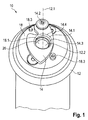
- FIG. 1 shows an embodiment of an apparatus 10 according to the invention for rotating a flat, fibrillated ribbon 22 for the production of an artificial turf, which comprises a hollow shaft 12 with a central axis of rotation 12.1 in its cavity 12.2, a deflection element 14 and a fastening element 18.
- the fastening element 18 is formed, for example, flat and with two screws at an outlet end of the hollow shaft 12, from which the continuous ribbon 22 exits the hollow shaft 12, attached.
- the fastening element 18 is aligned substantially orthogonal to the central axis of rotation 12.1.
- the fastening element 18 has a recess 18. 1, which more clearly in the Figures 3 and 5 you can see.
- the recess 18.1 may moreover have a circular flattening (not shown). This flattening is arranged for example on the side facing the hollow shaft 12. The inner surface of the recess 18.1 then does not run parallel to the axis of rotation 12.1 in the region of the flattening but is arranged angled relative to the axis of rotation 12.1. Thus, the continuous guiding or insertion of the ribbon is facilitated by the recess 18.1.
- the deflection element 14 is connected to the fastening element 18 via a pivot axis 14. Furthermore, the deflection element 14 has a recess 14.3.
- a part of the recess 14.3 forms a deflection region 14.1.
- This deflection range 14.1 is as in FIG. 5 to see in a deflection position of the deflection element 14, the ribbon 22 at.
- the flattening 14.4 may be disposed on the side facing away from the hollow shaft 12. However, a second flattening can also be arranged on the side facing the hollow shaft 12 (not shown). In the deflection region 14.1, the flats on both or only on one of the two sides can be more flattened in order to be able to guide the ribbon 22 even better.
- the fastening element 18 further has, in this embodiment, two stop elements 18.3, which limit the deflection of the deflection element 14 in a rest position and in a deflection position.
- FIGS. 2 and 3 show for illustrative purposes in a plan view only the fastening element 18 and the deflection element 14 in the rest position (FIG. FIG. 2 ) and in the deflection position ( FIG. 3 ).
- the hollow shaft 12 does not rotate about its central axis of rotation 12.1.
- the deflection element 14 is in the rest position.
- the recesses 14.3 and 18.1 are preferably concentric in this rest position and arranged one above the other about the central axis of rotation 12.1.
- an enlarged lead-through surface 20 is formed, through which the flat and fibrillated ribbon 22 can be carried out very well.
- this enlarged passage area 20 is so large that the ribbon 22 can be shot through with air. The start of the twisting process with the shooting of the ribbon 22 by air production is particularly advantageous.
- FIG. 3 the hollow shaft 12 rotates about its central axis of rotation 12.1 in the arrow direction. Due to the resulting centrifugal force, the deflection element 14 is deflected into the deflection position.
- FIG. 3 is to see an edge of the recess 18.1 of the fastener 18, which forms a limiting element 16 in this case. In this area, the recess 18.1 of the fastening element 18 preferably has an additional notch 18.2.
- the passage area 20 between the delimiting element 16 and the deflection area 14.1 is reduced in comparison to the rest position.
- the lead-through surface 20 in the deflection position of the deflection element 14 is dimensioned so that the flat and fibrillated ribbon 22 is deformed when it is guided or pulled through the lead-through surface 20.
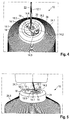
- FIGS. 4 and 5 show the inventive device 10 in a system that also has the fibrillated ribbon 22 and a yarn package 24 with Umwindegarn 24.1.
- the hollow shaft 12 is at least partially received in the yarn package 24.
- FIG. 4 shows the system in the rest position without rotation of the hollow shaft 12 with the yarn package 24th
- FIG. 5 shows the system in the deflection position at which the hollow shaft 12 rotates with the yarn package 24.
- the ribbon 22 abuts on the deflection region 14.1 and becomes as in FIG. 5 shown guided with the deflection region 14.1 to the limiting element 16 until it rests on this.
- the mass of the deflection element 14 is chosen so that the resulting centrifugal force is sufficient to push the continuously guided ribbon 22 outwards.
- the ribbon 22 Since the ribbon 22 is continuously guided by the hollow shaft 12 with known guide means (rollers, drives, etc., not shown), it is deformed by the reduced lead-through surface 20. Since the ribbon 22 bears against the limiting element 16, it is offset in this area from the central axis of rotation 12.1 of the hollow shaft 12. As a result of the rotational movement of the device 10 according to the invention, the ribbon 22 is thus guided on a circular path B parallel to the deflection plane of the deflection element 14. The ribbon 22 is guided by the guide means to a guide point (not shown) over an exit end of the hollow shaft 12. Consequently, the ribbon 22 is additionally twisted by the circular motion on the circular path B. In other words, the ribbon 22 thus moves over the exit end of the hollow shaft 12 substantially on a conical surface (dashed lines). In the guide point, the ribbon 22 is continuously guided so fixing that the twisting or deformation substantially does not unfold again.
- the Umwindegarn 24.1 is preferably deducted overhead and wrapped around the twisted and deformed ribbon 22 in the region of the guide point. This wrapping with the Umwindegarn 24.1 fixes the state of twisting and deformation of the ribbon 22nd
- the fixed ribbon 22 is preferably wound on a spool, etc. and transported to the tufting system.
- the ribbon 22 can be prepared separately from the tufting process for the tufting process, which results in further logistical advantages and cost advantages.
- the deflecting element 14 may also be arranged in the hollow space 12. 2 of the hollow shaft 12 (not shown). In another embodiment (not shown), it is also conceivable that the deflection element 14 is mounted directly on the hollow shaft 12 and an inner region of the hollow shaft 12 forms the limiting element 16. This simplified embodiment does not require the attachment via the fastener 18 and the guide or deformation by the notch 18.2. Depending on Tändchenart 22 and rotational speed is therefore possible to apply this embodiment of the invention.
Landscapes
- Engineering & Computer Science (AREA)
- Mechanical Engineering (AREA)
- Textile Engineering (AREA)
- Architecture (AREA)
- Civil Engineering (AREA)
- Structural Engineering (AREA)
- Yarns And Mechanical Finishing Of Yarns Or Ropes (AREA)
- Decoration Of Textiles (AREA)
- Treatment Of Fiber Materials (AREA)
Priority Applications (4)
| Application Number | Priority Date | Filing Date | Title |
|---|---|---|---|
| EP16170505.8A EP3246437B1 (fr) | 2016-05-19 | 2016-05-19 | Dispositif de blocage d'une petite bande fibrillee |
| ES16170505T ES2703986T3 (es) | 2016-05-19 | 2016-05-19 | Dispositivo para torcer una cinta fibrilada |
| US15/598,992 US10697091B2 (en) | 2016-05-19 | 2017-05-18 | Device for twisting a fibrillated strip |
| PCT/CA2017/050600 WO2017197520A1 (fr) | 2016-05-19 | 2017-05-18 | Dispositif de torsion de bande fibrillée |
Applications Claiming Priority (1)
| Application Number | Priority Date | Filing Date | Title |
|---|---|---|---|
| EP16170505.8A EP3246437B1 (fr) | 2016-05-19 | 2016-05-19 | Dispositif de blocage d'une petite bande fibrillee |
Publications (2)
| Publication Number | Publication Date |
|---|---|
| EP3246437A1 true EP3246437A1 (fr) | 2017-11-22 |
| EP3246437B1 EP3246437B1 (fr) | 2018-10-31 |
Family
ID=56087126
Family Applications (1)
| Application Number | Title | Priority Date | Filing Date |
|---|---|---|---|
| EP16170505.8A Active EP3246437B1 (fr) | 2016-05-19 | 2016-05-19 | Dispositif de blocage d'une petite bande fibrillee |
Country Status (4)
| Country | Link |
|---|---|
| US (1) | US10697091B2 (fr) |
| EP (1) | EP3246437B1 (fr) |
| ES (1) | ES2703986T3 (fr) |
| WO (1) | WO2017197520A1 (fr) |
Families Citing this family (1)
| Publication number | Priority date | Publication date | Assignee | Title |
|---|---|---|---|---|
| CN116446090B (zh) * | 2023-04-26 | 2024-01-12 | 河南省彩锦纺织有限公司 | 一种高效率的纺纱包芯装置 |
Citations (3)
| Publication number | Priority date | Publication date | Assignee | Title |
|---|---|---|---|---|
| EP1126051A1 (fr) * | 1999-04-08 | 2001-08-22 | Galan I llongueras, Jordi | Procede permettant d'obtenir un fil pour la confection de tissus speciaux et systeme permettant de realiser ce procede |
| WO2010102921A2 (fr) * | 2009-03-12 | 2010-09-16 | Oerlikon Textile Gmbh & Co. Kg | Procédé et dispositif pour la fabrication d'un fil d'herbe |
| WO2012164059A2 (fr) * | 2011-06-03 | 2012-12-06 | Oerlikon Textile Gmbh & Co. Kg | Procédé et dispositif de fabrication de fibres herbeuses synthétiques |
Family Cites Families (2)
| Publication number | Priority date | Publication date | Assignee | Title |
|---|---|---|---|---|
| US3899867A (en) | 1972-08-11 | 1975-08-19 | Spanco Yarns | Method and apparatus for forming helically wrapped yarns |
| US8999213B2 (en) | 2011-10-20 | 2015-04-07 | Tarkett, Inc. | Process for making artificial turf fibers |
-
2016
- 2016-05-19 ES ES16170505T patent/ES2703986T3/es active Active
- 2016-05-19 EP EP16170505.8A patent/EP3246437B1/fr active Active
-
2017
- 2017-05-18 US US15/598,992 patent/US10697091B2/en active Active
- 2017-05-18 WO PCT/CA2017/050600 patent/WO2017197520A1/fr not_active Ceased
Patent Citations (3)
| Publication number | Priority date | Publication date | Assignee | Title |
|---|---|---|---|---|
| EP1126051A1 (fr) * | 1999-04-08 | 2001-08-22 | Galan I llongueras, Jordi | Procede permettant d'obtenir un fil pour la confection de tissus speciaux et systeme permettant de realiser ce procede |
| WO2010102921A2 (fr) * | 2009-03-12 | 2010-09-16 | Oerlikon Textile Gmbh & Co. Kg | Procédé et dispositif pour la fabrication d'un fil d'herbe |
| WO2012164059A2 (fr) * | 2011-06-03 | 2012-12-06 | Oerlikon Textile Gmbh & Co. Kg | Procédé et dispositif de fabrication de fibres herbeuses synthétiques |
Also Published As
| Publication number | Publication date |
|---|---|
| WO2017197520A1 (fr) | 2017-11-23 |
| EP3246437B1 (fr) | 2018-10-31 |
| ES2703986T3 (es) | 2019-03-13 |
| US20170335490A1 (en) | 2017-11-23 |
| US10697091B2 (en) | 2020-06-30 |
Similar Documents
| Publication | Publication Date | Title |
|---|---|---|
| DE3138308A1 (de) | Verfahren und vorrichtung zum pneumatischen spleissen gesponnener faeden | |
| DE69921357T2 (de) | Spule für lichtwellenleiter bei der das innere ende des aufgewickelten leiters zugänglich ist | |
| DE3220402A1 (de) | Verfahren und vorrichtung zum erhoehen der haarigkeit und voluminositaet eines fadens | |
| DD154616A5 (de) | Verfahren und vorrichtung zum andrehen zweier faeden | |
| DE3133712A1 (de) | Pneumatische fadenspleissvorrichtung fuer gesponnene faeden | |
| CH660723A5 (de) | Pneumatische garnspleisseinrichtung zum spleissen von gesponnenen garnen. | |
| EP3246437B1 (fr) | Dispositif de blocage d'une petite bande fibrillee | |
| DE3607206C2 (de) | Verfahren und Vorrichtung zum Herstellen einer Spleißverbindung | |
| DE1660223C3 (de) | Verfahren zur Herstellung endloser fadenartiger Gebilde mit thermoplastischen Kunststoffen | |
| DE2854256C2 (de) | Abzugsvorrichtung für die Stoffbahn an einer Textilmaschine, insbesondere Webmaschine | |
| DE2348168A1 (de) | Vorrichtung zum einhaengen eines textilfadens an einem drehend angetriebenen traeger | |
| DE2429582C3 (de) | Bandkassette | |
| DE2543983B1 (de) | Garnpruefvorrichtung fuer Textilmaschinen | |
| DE69221211T2 (de) | Kassette für einen photographischen Film mit Lichtverschlusselementen sowie Verfahren zum Bearbeiten der Lichtverschlusselemente | |
| DE2347801A1 (de) | Verfahren zur herstellung vororientierter endlosfaeden | |
| DE2934762A1 (de) | Gekraeuseltes mischfilamentgarn und verfahren zu seiner herstellung | |
| WO2004005594A1 (fr) | Procede de filature | |
| DE102020103825B4 (de) | Verfahren zum maschinellen Wickeln eines kugelförmigen Wollknäuels | |
| DE2128504A1 (de) | Verfahren und Vorrichtung zum Auf wickeln fortlaufender Faden | |
| DE2128838A1 (de) | Vorrichtung und Verfahren zum Kräuseln von Fadenmaterial | |
| EP0929706B1 (fr) | Procede et dispositif pour vriller au moins deux fils en deplacement l'un autour de l'autre | |
| DE4222662B4 (de) | Vorrichtung zum Vorbereiten von Fadenenden | |
| DE3735752C2 (de) | Verfahren zur Herstellung von Glattgarn aus Polyamid oder Polyester | |
| EP1758807A1 (fr) | Procede et dispositif pour enrouler une bobine de fil | |
| DE585603C (de) | Abzugvorrichtung fuer Maschinen zur Herstellung elektrischer Kabel |
Legal Events
| Date | Code | Title | Description |
|---|---|---|---|
| PUAI | Public reference made under article 153(3) epc to a published international application that has entered the european phase |
Free format text: ORIGINAL CODE: 0009012 |
|
| STAA | Information on the status of an ep patent application or granted ep patent |
Free format text: STATUS: THE APPLICATION HAS BEEN PUBLISHED |
|
| AK | Designated contracting states |
Kind code of ref document: A1 Designated state(s): AL AT BE BG CH CY CZ DE DK EE ES FI FR GB GR HR HU IE IS IT LI LT LU LV MC MK MT NL NO PL PT RO RS SE SI SK SM TR |
|
| AX | Request for extension of the european patent |
Extension state: BA ME |
|
| STAA | Information on the status of an ep patent application or granted ep patent |
Free format text: STATUS: REQUEST FOR EXAMINATION WAS MADE |
|
| 17P | Request for examination filed |
Effective date: 20180522 |
|
| RBV | Designated contracting states (corrected) |
Designated state(s): AL AT BE BG CH CY CZ DE DK EE ES FI FR GB GR HR HU IE IS IT LI LT LU LV MC MK MT NL NO PL PT RO RS SE SI SK SM TR |
|
| GRAP | Despatch of communication of intention to grant a patent |
Free format text: ORIGINAL CODE: EPIDOSNIGR1 |
|
| STAA | Information on the status of an ep patent application or granted ep patent |
Free format text: STATUS: GRANT OF PATENT IS INTENDED |
|
| INTG | Intention to grant announced |
Effective date: 20180706 |
|
| GRAS | Grant fee paid |
Free format text: ORIGINAL CODE: EPIDOSNIGR3 |
|
| GRAA | (expected) grant |
Free format text: ORIGINAL CODE: 0009210 |
|
| STAA | Information on the status of an ep patent application or granted ep patent |
Free format text: STATUS: THE PATENT HAS BEEN GRANTED |
|
| AK | Designated contracting states |
Kind code of ref document: B1 Designated state(s): AL AT BE BG CH CY CZ DE DK EE ES FI FR GB GR HR HU IE IS IT LI LT LU LV MC MK MT NL NO PL PT RO RS SE SI SK SM TR |
|
| REG | Reference to a national code |
Ref country code: CH Ref legal event code: EP Ref country code: GB Ref legal event code: FG4D Free format text: NOT ENGLISH |
|
| REG | Reference to a national code |
Ref country code: AT Ref legal event code: REF Ref document number: 1059506 Country of ref document: AT Kind code of ref document: T Effective date: 20181115 |
|
| REG | Reference to a national code |
Ref country code: DE Ref legal event code: R096 Ref document number: 502016002357 Country of ref document: DE |
|
| REG | Reference to a national code |
Ref country code: IE Ref legal event code: FG4D Free format text: LANGUAGE OF EP DOCUMENT: GERMAN |
|
| REG | Reference to a national code |
Ref country code: NL Ref legal event code: FP |
|
| REG | Reference to a national code |
Ref country code: CH Ref legal event code: NV Representative=s name: RENTSCH PARTNER AG, CH |
|
| REG | Reference to a national code |
Ref country code: LT Ref legal event code: MG4D |
|
| REG | Reference to a national code |
Ref country code: ES Ref legal event code: FG2A Ref document number: 2703986 Country of ref document: ES Kind code of ref document: T3 Effective date: 20190313 |
|
| PG25 | Lapsed in a contracting state [announced via postgrant information from national office to epo] |
Ref country code: FI Free format text: LAPSE BECAUSE OF FAILURE TO SUBMIT A TRANSLATION OF THE DESCRIPTION OR TO PAY THE FEE WITHIN THE PRESCRIBED TIME-LIMIT Effective date: 20181031 Ref country code: LV Free format text: LAPSE BECAUSE OF FAILURE TO SUBMIT A TRANSLATION OF THE DESCRIPTION OR TO PAY THE FEE WITHIN THE PRESCRIBED TIME-LIMIT Effective date: 20181031 Ref country code: IS Free format text: LAPSE BECAUSE OF FAILURE TO SUBMIT A TRANSLATION OF THE DESCRIPTION OR TO PAY THE FEE WITHIN THE PRESCRIBED TIME-LIMIT Effective date: 20190228 Ref country code: HR Free format text: LAPSE BECAUSE OF FAILURE TO SUBMIT A TRANSLATION OF THE DESCRIPTION OR TO PAY THE FEE WITHIN THE PRESCRIBED TIME-LIMIT Effective date: 20181031 Ref country code: NO Free format text: LAPSE BECAUSE OF FAILURE TO SUBMIT A TRANSLATION OF THE DESCRIPTION OR TO PAY THE FEE WITHIN THE PRESCRIBED TIME-LIMIT Effective date: 20190131 Ref country code: BG Free format text: LAPSE BECAUSE OF FAILURE TO SUBMIT A TRANSLATION OF THE DESCRIPTION OR TO PAY THE FEE WITHIN THE PRESCRIBED TIME-LIMIT Effective date: 20190131 Ref country code: PL Free format text: LAPSE BECAUSE OF FAILURE TO SUBMIT A TRANSLATION OF THE DESCRIPTION OR TO PAY THE FEE WITHIN THE PRESCRIBED TIME-LIMIT Effective date: 20181031 Ref country code: LT Free format text: LAPSE BECAUSE OF FAILURE TO SUBMIT A TRANSLATION OF THE DESCRIPTION OR TO PAY THE FEE WITHIN THE PRESCRIBED TIME-LIMIT Effective date: 20181031 |
|
| PG25 | Lapsed in a contracting state [announced via postgrant information from national office to epo] |
Ref country code: AL Free format text: LAPSE BECAUSE OF FAILURE TO SUBMIT A TRANSLATION OF THE DESCRIPTION OR TO PAY THE FEE WITHIN THE PRESCRIBED TIME-LIMIT Effective date: 20181031 Ref country code: PT Free format text: LAPSE BECAUSE OF FAILURE TO SUBMIT A TRANSLATION OF THE DESCRIPTION OR TO PAY THE FEE WITHIN THE PRESCRIBED TIME-LIMIT Effective date: 20190301 Ref country code: SE Free format text: LAPSE BECAUSE OF FAILURE TO SUBMIT A TRANSLATION OF THE DESCRIPTION OR TO PAY THE FEE WITHIN THE PRESCRIBED TIME-LIMIT Effective date: 20181031 Ref country code: GR Free format text: LAPSE BECAUSE OF FAILURE TO SUBMIT A TRANSLATION OF THE DESCRIPTION OR TO PAY THE FEE WITHIN THE PRESCRIBED TIME-LIMIT Effective date: 20190201 Ref country code: RS Free format text: LAPSE BECAUSE OF FAILURE TO SUBMIT A TRANSLATION OF THE DESCRIPTION OR TO PAY THE FEE WITHIN THE PRESCRIBED TIME-LIMIT Effective date: 20181031 |
|
| PG25 | Lapsed in a contracting state [announced via postgrant information from national office to epo] |
Ref country code: CZ Free format text: LAPSE BECAUSE OF FAILURE TO SUBMIT A TRANSLATION OF THE DESCRIPTION OR TO PAY THE FEE WITHIN THE PRESCRIBED TIME-LIMIT Effective date: 20181031 Ref country code: IT Free format text: LAPSE BECAUSE OF FAILURE TO SUBMIT A TRANSLATION OF THE DESCRIPTION OR TO PAY THE FEE WITHIN THE PRESCRIBED TIME-LIMIT Effective date: 20181031 Ref country code: DK Free format text: LAPSE BECAUSE OF FAILURE TO SUBMIT A TRANSLATION OF THE DESCRIPTION OR TO PAY THE FEE WITHIN THE PRESCRIBED TIME-LIMIT Effective date: 20181031 |
|
| REG | Reference to a national code |
Ref country code: DE Ref legal event code: R097 Ref document number: 502016002357 Country of ref document: DE |
|
| PG25 | Lapsed in a contracting state [announced via postgrant information from national office to epo] |
Ref country code: EE Free format text: LAPSE BECAUSE OF FAILURE TO SUBMIT A TRANSLATION OF THE DESCRIPTION OR TO PAY THE FEE WITHIN THE PRESCRIBED TIME-LIMIT Effective date: 20181031 Ref country code: SM Free format text: LAPSE BECAUSE OF FAILURE TO SUBMIT A TRANSLATION OF THE DESCRIPTION OR TO PAY THE FEE WITHIN THE PRESCRIBED TIME-LIMIT Effective date: 20181031 Ref country code: RO Free format text: LAPSE BECAUSE OF FAILURE TO SUBMIT A TRANSLATION OF THE DESCRIPTION OR TO PAY THE FEE WITHIN THE PRESCRIBED TIME-LIMIT Effective date: 20181031 Ref country code: SK Free format text: LAPSE BECAUSE OF FAILURE TO SUBMIT A TRANSLATION OF THE DESCRIPTION OR TO PAY THE FEE WITHIN THE PRESCRIBED TIME-LIMIT Effective date: 20181031 |
|
| PLBE | No opposition filed within time limit |
Free format text: ORIGINAL CODE: 0009261 |
|
| STAA | Information on the status of an ep patent application or granted ep patent |
Free format text: STATUS: NO OPPOSITION FILED WITHIN TIME LIMIT |
|
| 26N | No opposition filed |
Effective date: 20190801 |
|
| PG25 | Lapsed in a contracting state [announced via postgrant information from national office to epo] |
Ref country code: SI Free format text: LAPSE BECAUSE OF FAILURE TO SUBMIT A TRANSLATION OF THE DESCRIPTION OR TO PAY THE FEE WITHIN THE PRESCRIBED TIME-LIMIT Effective date: 20181031 |
|
| REG | Reference to a national code |
Ref country code: CH Ref legal event code: PL |
|
| REG | Reference to a national code |
Ref country code: NL Ref legal event code: MM Effective date: 20190601 |
|
| PG25 | Lapsed in a contracting state [announced via postgrant information from national office to epo] |
Ref country code: CH Free format text: LAPSE BECAUSE OF NON-PAYMENT OF DUE FEES Effective date: 20190531 Ref country code: LI Free format text: LAPSE BECAUSE OF NON-PAYMENT OF DUE FEES Effective date: 20190531 Ref country code: MC Free format text: LAPSE BECAUSE OF FAILURE TO SUBMIT A TRANSLATION OF THE DESCRIPTION OR TO PAY THE FEE WITHIN THE PRESCRIBED TIME-LIMIT Effective date: 20181031 |
|
| REG | Reference to a national code |
Ref country code: BE Ref legal event code: MM Effective date: 20190531 |
|
| PG25 | Lapsed in a contracting state [announced via postgrant information from national office to epo] |
Ref country code: LU Free format text: LAPSE BECAUSE OF NON-PAYMENT OF DUE FEES Effective date: 20190519 |
|
| PG25 | Lapsed in a contracting state [announced via postgrant information from national office to epo] |
Ref country code: TR Free format text: LAPSE BECAUSE OF FAILURE TO SUBMIT A TRANSLATION OF THE DESCRIPTION OR TO PAY THE FEE WITHIN THE PRESCRIBED TIME-LIMIT Effective date: 20181031 |
|
| PG25 | Lapsed in a contracting state [announced via postgrant information from national office to epo] |
Ref country code: IE Free format text: LAPSE BECAUSE OF NON-PAYMENT OF DUE FEES Effective date: 20190519 Ref country code: NL Free format text: LAPSE BECAUSE OF NON-PAYMENT OF DUE FEES Effective date: 20190601 |
|
| PG25 | Lapsed in a contracting state [announced via postgrant information from national office to epo] |
Ref country code: BE Free format text: LAPSE BECAUSE OF NON-PAYMENT OF DUE FEES Effective date: 20190531 |
|
| PG25 | Lapsed in a contracting state [announced via postgrant information from national office to epo] |
Ref country code: FR Free format text: LAPSE BECAUSE OF NON-PAYMENT OF DUE FEES Effective date: 20190531 |
|
| REG | Reference to a national code |
Ref country code: ES Ref legal event code: FD2A Effective date: 20200925 |
|
| PG25 | Lapsed in a contracting state [announced via postgrant information from national office to epo] |
Ref country code: ES Free format text: LAPSE BECAUSE OF NON-PAYMENT OF DUE FEES Effective date: 20190520 |
|
| PG25 | Lapsed in a contracting state [announced via postgrant information from national office to epo] |
Ref country code: CY Free format text: LAPSE BECAUSE OF FAILURE TO SUBMIT A TRANSLATION OF THE DESCRIPTION OR TO PAY THE FEE WITHIN THE PRESCRIBED TIME-LIMIT Effective date: 20181031 |
|
| PG25 | Lapsed in a contracting state [announced via postgrant information from national office to epo] |
Ref country code: HU Free format text: LAPSE BECAUSE OF FAILURE TO SUBMIT A TRANSLATION OF THE DESCRIPTION OR TO PAY THE FEE WITHIN THE PRESCRIBED TIME-LIMIT; INVALID AB INITIO Effective date: 20160519 Ref country code: MT Free format text: LAPSE BECAUSE OF FAILURE TO SUBMIT A TRANSLATION OF THE DESCRIPTION OR TO PAY THE FEE WITHIN THE PRESCRIBED TIME-LIMIT Effective date: 20181031 |
|
| PG25 | Lapsed in a contracting state [announced via postgrant information from national office to epo] |
Ref country code: MK Free format text: LAPSE BECAUSE OF FAILURE TO SUBMIT A TRANSLATION OF THE DESCRIPTION OR TO PAY THE FEE WITHIN THE PRESCRIBED TIME-LIMIT Effective date: 20181031 |
|
| PGFP | Annual fee paid to national office [announced via postgrant information from national office to epo] |
Ref country code: AT Payment date: 20220425 Year of fee payment: 7 |
|
| REG | Reference to a national code |
Ref country code: AT Ref legal event code: MM01 Ref document number: 1059506 Country of ref document: AT Kind code of ref document: T Effective date: 20230519 |
|
| PG25 | Lapsed in a contracting state [announced via postgrant information from national office to epo] |
Ref country code: AT Free format text: LAPSE BECAUSE OF NON-PAYMENT OF DUE FEES Effective date: 20230519 |
|
| PGFP | Annual fee paid to national office [announced via postgrant information from national office to epo] |
Ref country code: DE Payment date: 20250325 Year of fee payment: 10 |
|
| PGFP | Annual fee paid to national office [announced via postgrant information from national office to epo] |
Ref country code: GB Payment date: 20260312 Year of fee payment: 11 |