EP3246470A1 - Appareil de traitement des sols et procede de production de lamelles de paroi - Google Patents
Appareil de traitement des sols et procede de production de lamelles de paroi Download PDFInfo
- Publication number
- EP3246470A1 EP3246470A1 EP16169918.6A EP16169918A EP3246470A1 EP 3246470 A1 EP3246470 A1 EP 3246470A1 EP 16169918 A EP16169918 A EP 16169918A EP 3246470 A1 EP3246470 A1 EP 3246470A1
- Authority
- EP
- European Patent Office
- Prior art keywords
- drilling
- mixing tools
- conveyor coil
- soil
- mixing
- Prior art date
- Legal status (The legal status is an assumption and is not a legal conclusion. Google has not performed a legal analysis and makes no representation as to the accuracy of the status listed.)
- Granted
Links
Images
Classifications
-
- E—FIXED CONSTRUCTIONS
- E02—HYDRAULIC ENGINEERING; FOUNDATIONS; SOIL SHIFTING
- E02D—FOUNDATIONS; EXCAVATIONS; EMBANKMENTS; UNDERGROUND OR UNDERWATER STRUCTURES
- E02D5/00—Bulkheads, piles, or other structural elements specially adapted to foundation engineering
- E02D5/18—Bulkheads or similar walls made solely of concrete in situ
-
- E—FIXED CONSTRUCTIONS
- E02—HYDRAULIC ENGINEERING; FOUNDATIONS; SOIL SHIFTING
- E02D—FOUNDATIONS; EXCAVATIONS; EMBANKMENTS; UNDERGROUND OR UNDERWATER STRUCTURES
- E02D17/00—Excavations; Bordering of excavations; Making embankments
- E02D17/13—Foundation slots or slits; Implements for making these slots or slits
-
- E—FIXED CONSTRUCTIONS
- E02—HYDRAULIC ENGINEERING; FOUNDATIONS; SOIL SHIFTING
- E02D—FOUNDATIONS; EXCAVATIONS; EMBANKMENTS; UNDERGROUND OR UNDERWATER STRUCTURES
- E02D3/00—Improving or preserving soil or rock, e.g. preserving permafrost soil
- E02D3/12—Consolidating by placing solidifying or pore-filling substances in the soil
- E02D3/126—Consolidating by placing solidifying or pore-filling substances in the soil and mixing by rotating blades
-
- E—FIXED CONSTRUCTIONS
- E02—HYDRAULIC ENGINEERING; FOUNDATIONS; SOIL SHIFTING
- E02D—FOUNDATIONS; EXCAVATIONS; EMBANKMENTS; UNDERGROUND OR UNDERWATER STRUCTURES
- E02D5/00—Bulkheads, piles, or other structural elements specially adapted to foundation engineering
- E02D5/18—Bulkheads or similar walls made solely of concrete in situ
- E02D5/187—Bulkheads or similar walls made solely of concrete in situ the bulkheads or walls being made continuously, e.g. excavating and constructing bulkheads or walls in the same process, without joints
Definitions
- the invention relates to a harrow with at least two mutually parallel, elongated drilling and mixing tools, comprising a rod-shaped body, on which a first conveyor coil and at least one second conveyor coil are arranged, which is axially spaced from the first conveyor coil, according to the preamble of Claim 1.
- the invention further relates to a method for producing wall lamellae in a floor having at least two mutually parallel, elongated drilling and mixing tools, which have a lower first conveyor coil and at least one upper second conveyor coil, wherein the drilling and mixing tools are driven in rotation and in the Soil are sunk, while soil material is removed and the removed soil material is mixed with a supplied binder suspension to a soil mortar, which hardens after pulling the drilling and mixing tools from the ground to the wall lamella, according to the preamble of claim 12th
- the individual wall lamellae must be created with a very exact position to each other.
- drilling and mixing tools to use, which have a corresponding length.
- the risk of drilling and mixing tools sinking into the ground increases. This not only affects the sealing performance of the entire wall. Rather, considerable transverse and bending forces can be exerted on the typically 10 to 20 m long drilling and mixing tools by running the individual rod-shaped drilling and mixing tools.
- the dynamic load during the rotating drive of the tools leads to a significant wear on the conveyor coils, the bar-shaped base body and the pivot bearings of the individual tools when bleeding.
- the invention has for its object to provide a harrow and a method for producing wall lamella, with which wall lamellae can be produced efficiently and wear.
- the soil cultivation device is characterized in that at least at a drilling and mixing element at a lower end of the first conveyor coil is formed with an outer diameter which is larger than an outer diameter of the second conveyor coil, which is arranged above the first conveyor coil.
- the lower first conveyor coil is provided with a larger outer diameter, through which the bore diameter the created hole is determined. It is advantageous according to a finding of the invention that the overlying second conveyor coil, which is used primarily for the transport and mixing of the removed soil material, has a smaller diameter. Thus, the second conveyor coil when drilling the hole is not or hardly in frictional contact with the bore wall. Even with a bleeding of the rod-shaped drilling and mixing tool, the upper second conveying helix does not necessarily reach a wear-resistant frictional contact with the bore wall.
- the different design of the first conveyor coil and the second conveyor coil leads to a reduction of the Reibungsverschl constituentes on the second conveyor coil and, accordingly, to a reduction in the force acting on the rod-shaped base body and on the pivot bearing lateral forces.
- the first conveyor coil can be designed with an arbitrary length.
- the lower first conveyor coil comprises a half to two helix turns, preferably a single helix rotation.
- the axial length of the lower first conveyor coil remains relatively small, so that the friction wear occurring there is small.
- the formation of a half to two spiral turns is sufficient for the function of the first conveyor coil for reliable removal of removed soil material from the bottom of the hole upwards.
- a further preferred embodiment of the invention consists in that at least one transverse yoke, which connects the drilling and mixing tools, is arranged between the lower first conveying spiral and the upper, second conveying spiral.
- at least one transverse yoke which connects the drilling and mixing tools, is arranged between the lower first conveying spiral and the upper, second conveying spiral.
- two or more yokes may be provided.
- At least one transverse yoke is arranged directly above the first conveyor helix.
- the sections are combined with the lower first conveyor coils of the at least two drilling and mixing tools via at least one transverse yoke to a replaceable unit, which are detachably and non-rotatably connected via releasable connection means each with the rod-shaped bodies of the overlying second conveyor coils can.
- a replaceable unit which are detachably and non-rotatably connected via releasable connection means each with the rod-shaped bodies of the overlying second conveyor coils can.
- a particularly good stiffening of the overall arrangement is achieved according to a variant in that the drilling and mixing tools are rotatably mounted in the at least one transverse yoke.
- mixing and / or stirring elements are additionally arranged at least in the region of the upper second conveying spiral.
- the mixing and stirring elements may be formed, for example, by paddles, rods or other mechanical stirring elements.
- the second conveyor coil may be formed by a plurality of sections. Between the individual sections of the conveyor spiral, the individual, preferably radially extending mixing and / or stirring elements may be attached to the rod-shaped base body.
- a removal device for removing soil material is attached to a lower tip of the drilling and mixing tools.
- the removal device can have one or more removal teeth.
- the removal device preferably extends radially outward from a central region. Preferably, the removal device can extend over the entire bore diameter.
- An outer diameter of the conveyor coil of the intermediate element may be smaller than or equal to the outer diameter of the upper second conveyor coil of the adjacent mixing and drilling tools.
- the intermediate element it is particularly advantageous for the intermediate element to have a smaller outer diameter, at least in its lower region than the adjacent drilling and mixing tools.
- the lower region of the intermediate element may be free of a lower conveying spiral.
- individual mixing and / or stirring elements may be arranged in the lower region of the intermediate element.
- a removal device for removing soil material in the intermediate region between the adjacent drilling and mixing tools may be provided.
- the intermediate element and / or the rod-shaped basic body may be formed as tubes, via which binder suspension is fed into the bore.
- a preferred embodiment of a soil cultivation device is characterized in that a mast is provided, along which a carriage is movably guided, on which the drilling and mixing tools are rotatably mounted. With the carriage so the drilling and mixing tools can be moved together as a tool unit together.
- At least one rotary drive for rotating driving of the drilling and mixing tools is arranged on the carriage.
- the rotary drive is preferably a hydraulic motor.
- the carrier device is in particular a tracked vehicle with a superstructure rotatably mounted thereon, on which the vertically directed mast is mounted with the tool unit.
- the method according to the invention is characterized in that a drill diameter which is greater than an outer diameter of the upper second delivery helix is produced by the lower first delivery helix on at least one drilling and mixing tool, wherein the upper second delivery helix is spaced from a bore wall.
- a soil cultivating device is used, as previously described.
- wall lamellae can be produced in the soil in an efficient way.
- the occurring wear on the drilling and mixing tools and the tillage equipment is kept low overall.
- the smaller diameter second conveyor coil is sufficient to the floor mortar to mix and to keep the solid components in suspension.
- Due to the distance from the wall, an annular channel is formed around the second conveying spiral, which promotes an advantageous circulation in the bore.
- a difference in diameter may be between 5 cm and 50 cm, preferably in the range of about 20 cm.
- the invention will be described in more detail below with reference to a preferred embodiment, which is shown schematically in the drawing.
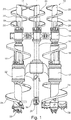
- the single drawing shows a front view of a lower part of a harrow 10 according to the invention.
- the soil cultivation device 10 according to the invention is constructed with respect to the carrier device, not shown, with a mast, as it is known from EP 2 395 153 B1 is known.
- a tool unit 11 with two elongated drilling and mixing tools 20 are mounted vertically movable in the soil cultivation device 10 according to the invention.
- a central, rod-shaped intermediate element 30 is arranged between the two parallel drilling and mixing tools 20, a central, rod-shaped intermediate element 30 is arranged.
- the two drilling and mixing tools 20 are coupled together with the intermediate element 30 via a lower first transverse yoke 12 and an upper second transverse yoke 14.
- first transverse yoke 12 and the second transverse yoke 14 the drilling and mixing tools 20 and the rod-shaped intermediate member 30 are rotatably mounted in each case via pivot bearings.
- the two drilling and mixing tools 20 each have a lower first conveying helix 24 on their rod-shaped base body 22.
- the first conveying spiral 24 extends from a removal device 28 with soil removal teeth over a turn to the lower end of the first transverse yoke 12.
- the two drilling and mixing tools 20 each have an upper second conveying spiral 26, which each have several turns.
- an outer diameter of the lower first delivery helix 24 is greater than an outer diameter of the upper second delivery helix 26.
- a bore having a first bore diameter in the bottom is created together with the lower first conveying helix 24. Due to the larger outer diameter of the lower first conveyor coil 24, the smaller-diameter upper second conveyor coils 26 do not contact the bore wall during drilling. As a result, friction when drilling the bore is avoided, which has a positive effect on the drive power and the friction wear on the drilling and mixing tools 20.
- the rod-shaped intermediate element 30 is also provided at its lower end with a removal device 28 with Abtragszähnen. In its lower region, the intermediate element 30 is held free of a conveyor coil. In an intermediate region between the first transverse yoke 12 and the second transverse yoke 14 further Abtragszähne 32 are mounted, which extend approximately radially to the axis of rotation of the intermediate member 30 to the outside and below.
- a tubular base body of the rod-shaped intermediate element 30 is provided with a delivery helix 36.
- the delivery helix 36 can have the same direction of rotation and configuration as the second delivery helix 26 of the right-side drilling and mixing tool 20, while the second delivery helix 26 of the left-side drilling and mixing tool 20 has an opposite helical rotation.
- a binder suspension can be introduced into the bore, preferably under pressure, from outside the borehole.
- the region of the lower first conveying helix 24 with the removal devices 28 of the two drilling and mixing tools 20 is detachably attached to the rod-shaped basic bodies 22 via a first connecting device 16.
- the first connecting device 16 is a splined axial spline. This lower region is connected to one another via the first transverse yoke 12 and constitutes a replaceable unit.
- a further segment of the drilling and mixing tools 20 and the intermediate element 30 can be easily detachably attached to the respective rod-shaped base bodies 22.
Landscapes
- Engineering & Computer Science (AREA)
- Structural Engineering (AREA)
- Mining & Mineral Resources (AREA)
- Life Sciences & Earth Sciences (AREA)
- Civil Engineering (AREA)
- Paleontology (AREA)
- General Life Sciences & Earth Sciences (AREA)
- General Engineering & Computer Science (AREA)
- Agronomy & Crop Science (AREA)
- Environmental & Geological Engineering (AREA)
- Soil Sciences (AREA)
- Bulkheads Adapted To Foundation Construction (AREA)
- Soil Working Implements (AREA)
- Consolidation Of Soil By Introduction Of Solidifying Substances Into Soil (AREA)
Priority Applications (2)
| Application Number | Priority Date | Filing Date | Title |
|---|---|---|---|
| EP16169918.6A EP3246470B1 (fr) | 2016-05-17 | 2016-05-17 | Appareil de traîtement des sols et procédé de production de lamelles de paroi |
| US15/583,840 US10100481B2 (en) | 2016-05-17 | 2017-05-01 | Ground-working machine and method for producing wall panels |
Applications Claiming Priority (1)
| Application Number | Priority Date | Filing Date | Title |
|---|---|---|---|
| EP16169918.6A EP3246470B1 (fr) | 2016-05-17 | 2016-05-17 | Appareil de traîtement des sols et procédé de production de lamelles de paroi |
Publications (2)
| Publication Number | Publication Date |
|---|---|
| EP3246470A1 true EP3246470A1 (fr) | 2017-11-22 |
| EP3246470B1 EP3246470B1 (fr) | 2018-12-19 |
Family
ID=56026670
Family Applications (1)
| Application Number | Title | Priority Date | Filing Date |
|---|---|---|---|
| EP16169918.6A Active EP3246470B1 (fr) | 2016-05-17 | 2016-05-17 | Appareil de traîtement des sols et procédé de production de lamelles de paroi |
Country Status (2)
| Country | Link |
|---|---|
| US (1) | US10100481B2 (fr) |
| EP (1) | EP3246470B1 (fr) |
Citations (3)
| Publication number | Priority date | Publication date | Assignee | Title |
|---|---|---|---|---|
| US5368415A (en) * | 1993-02-18 | 1994-11-29 | S. M. W. Seiko | Spiral flights for improved soil mixing and efficient boring for use on multi-shaft auger soil mixing apparatus |
| DE10238646B3 (de) | 2002-08-23 | 2004-04-01 | Bauer Spezialtiefbau Gmbh | Dichte Mixed-in-Place-Wände |
| EP2395153B1 (fr) | 2010-06-11 | 2013-03-27 | Bauer Spezialtiefbau GmbH | Procédé et dispositif de fabrication de lamelles murales dans le sol |
Family Cites Families (3)
| Publication number | Priority date | Publication date | Assignee | Title |
|---|---|---|---|---|
| US4906142A (en) * | 1988-03-23 | 1990-03-06 | S.M.W. Seiko, Inc. | Side cutting blades for multi-shaft auger system and improved soil mixing wall formation process |
| US5118223A (en) * | 1988-03-23 | 1992-06-02 | Osamu Taki | Multi-shaft auger apparatus and process for forming soilcrete columns and walls and grids in situ in soil |
| US5575345A (en) | 1994-11-15 | 1996-11-19 | Chemical Grouting Company. Ltd. | Multi shaft drilling unit |
-
2016
- 2016-05-17 EP EP16169918.6A patent/EP3246470B1/fr active Active
-
2017
- 2017-05-01 US US15/583,840 patent/US10100481B2/en active Active
Patent Citations (3)
| Publication number | Priority date | Publication date | Assignee | Title |
|---|---|---|---|---|
| US5368415A (en) * | 1993-02-18 | 1994-11-29 | S. M. W. Seiko | Spiral flights for improved soil mixing and efficient boring for use on multi-shaft auger soil mixing apparatus |
| DE10238646B3 (de) | 2002-08-23 | 2004-04-01 | Bauer Spezialtiefbau Gmbh | Dichte Mixed-in-Place-Wände |
| EP2395153B1 (fr) | 2010-06-11 | 2013-03-27 | Bauer Spezialtiefbau GmbH | Procédé et dispositif de fabrication de lamelles murales dans le sol |
Also Published As
| Publication number | Publication date |
|---|---|
| US20170335535A1 (en) | 2017-11-23 |
| EP3246470B1 (fr) | 2018-12-19 |
| US10100481B2 (en) | 2018-10-16 |
Similar Documents
| Publication | Publication Date | Title |
|---|---|---|
| DE10308538B4 (de) | Verfahren zum Herstellen einer Schlitzwand im Boden, Schlitzwandfräse und Schlitzwandfräsvorrichtung | |
| EP1640509B2 (fr) | Procédé et appareil pour creuser des tranchées dans le sol | |
| EP2133507B1 (fr) | Dispositif et procédé de forage | |
| EP3336301B1 (fr) | Perforatrice rotative et procédé de fabrication d'un alésage | |
| EP0699888A2 (fr) | Détermination du diamètre ou de l'épaisseur d'éléments d'une paroi | |
| EP0855489B1 (fr) | Perçoir qui déplace la terre | |
| DE2717013C2 (de) | Zahnärztliches Handstück | |
| EP1580327B1 (fr) | Appareil pour creuser des tranchées dans le sol | |
| DE2439063C3 (de) | Vorrichtung zum Herstellen von Bohrlöchern im Boden | |
| EP2876246B1 (fr) | Tarière pour le forage terrestre | |
| EP2011958B1 (fr) | Tarière | |
| DE2624079C2 (de) | Verfahren und Bohrgerät zur Herstellung von Gesteins- und Erdbohrlöchern besonderen Querschnitts | |
| EP2423388A1 (fr) | Procédé et dispositif de fabrication d'une paroi moulée | |
| DE10258605A1 (de) | Bohrwerkzeug mit abrasiven Schneidelementen und eine dieses antreibende Bohrmaschine | |
| EP4013564B1 (fr) | Scie à câble | |
| EP2395153B1 (fr) | Procédé et dispositif de fabrication de lamelles murales dans le sol | |
| EP3246470B1 (fr) | Appareil de traîtement des sols et procédé de production de lamelles de paroi | |
| EP3456914B1 (fr) | Dispositif de forage double tête et procédé de réalisation d'un forage | |
| DE4114457C1 (fr) | ||
| DE8803902U1 (de) | Vorrichtung zur Bodenbearbeitung | |
| DE4014752C2 (de) | Längsschneidarm für Vortriebs- und Abbauzwecke u. dgl. | |
| EP2520756B1 (fr) | Elément de mât pour un appareil de forage | |
| AT393292B (de) | Vorrichtung zur herstellung von durch zugabe von binde- oder abdichtemitteln verdichteten bodenabschnitten | |
| DE2946873C2 (de) | Drehangetriebenes Erdbohrgerät | |
| EP2666911B1 (fr) | Procédé de fabrication d'une paroi en mortier fixée dans le sol |
Legal Events
| Date | Code | Title | Description |
|---|---|---|---|
| PUAI | Public reference made under article 153(3) epc to a published international application that has entered the european phase |
Free format text: ORIGINAL CODE: 0009012 |
|
| STAA | Information on the status of an ep patent application or granted ep patent |
Free format text: STATUS: THE APPLICATION HAS BEEN PUBLISHED |
|
| AK | Designated contracting states |
Kind code of ref document: A1 Designated state(s): AL AT BE BG CH CY CZ DE DK EE ES FI FR GB GR HR HU IE IS IT LI LT LU LV MC MK MT NL NO PL PT RO RS SE SI SK SM TR |
|
| AX | Request for extension of the european patent |
Extension state: BA ME |
|
| RAP1 | Party data changed (applicant data changed or rights of an application transferred) |
Owner name: BAUER SPEZIALTIEFBAU GMBH |
|
| STAA | Information on the status of an ep patent application or granted ep patent |
Free format text: STATUS: REQUEST FOR EXAMINATION WAS MADE |
|
| 17P | Request for examination filed |
Effective date: 20180328 |
|
| RBV | Designated contracting states (corrected) |
Designated state(s): AL AT BE BG CH CY CZ DE DK EE ES FI FR GB GR HR HU IE IS IT LI LT LU LV MC MK MT NL NO PL PT RO RS SE SI SK SM TR |
|
| RIC1 | Information provided on ipc code assigned before grant |
Ipc: E02D 5/18 20060101ALI20180613BHEP Ipc: E02D 17/13 20060101ALI20180613BHEP Ipc: E02D 3/12 20060101AFI20180613BHEP |
|
| GRAP | Despatch of communication of intention to grant a patent |
Free format text: ORIGINAL CODE: EPIDOSNIGR1 |
|
| STAA | Information on the status of an ep patent application or granted ep patent |
Free format text: STATUS: GRANT OF PATENT IS INTENDED |
|
| INTG | Intention to grant announced |
Effective date: 20180730 |
|
| GRAS | Grant fee paid |
Free format text: ORIGINAL CODE: EPIDOSNIGR3 |
|
| GRAA | (expected) grant |
Free format text: ORIGINAL CODE: 0009210 |
|
| STAA | Information on the status of an ep patent application or granted ep patent |
Free format text: STATUS: THE PATENT HAS BEEN GRANTED |
|
| AK | Designated contracting states |
Kind code of ref document: B1 Designated state(s): AL AT BE BG CH CY CZ DE DK EE ES FI FR GB GR HR HU IE IS IT LI LT LU LV MC MK MT NL NO PL PT RO RS SE SI SK SM TR |
|
| REG | Reference to a national code |
Ref country code: GB Ref legal event code: FG4D Free format text: NOT ENGLISH |
|
| REG | Reference to a national code |
Ref country code: CH Ref legal event code: EP |
|
| REG | Reference to a national code |
Ref country code: IE Ref legal event code: FG4D Free format text: LANGUAGE OF EP DOCUMENT: GERMAN |
|
| REG | Reference to a national code |
Ref country code: DE Ref legal event code: R096 Ref document number: 502016002881 Country of ref document: DE |
|
| REG | Reference to a national code |
Ref country code: AT Ref legal event code: REF Ref document number: 1078860 Country of ref document: AT Kind code of ref document: T Effective date: 20190115 |
|
| REG | Reference to a national code |
Ref country code: CH Ref legal event code: NV Representative=s name: BOGENSBERGER PATENT- AND MARKENBUERO DR. BURKH, LI |
|
| REG | Reference to a national code |
Ref country code: NL Ref legal event code: FP |
|
| PG25 | Lapsed in a contracting state [announced via postgrant information from national office to epo] |
Ref country code: HR Free format text: LAPSE BECAUSE OF FAILURE TO SUBMIT A TRANSLATION OF THE DESCRIPTION OR TO PAY THE FEE WITHIN THE PRESCRIBED TIME-LIMIT Effective date: 20181219 Ref country code: LT Free format text: LAPSE BECAUSE OF FAILURE TO SUBMIT A TRANSLATION OF THE DESCRIPTION OR TO PAY THE FEE WITHIN THE PRESCRIBED TIME-LIMIT Effective date: 20181219 Ref country code: BG Free format text: LAPSE BECAUSE OF FAILURE TO SUBMIT A TRANSLATION OF THE DESCRIPTION OR TO PAY THE FEE WITHIN THE PRESCRIBED TIME-LIMIT Effective date: 20190319 Ref country code: FI Free format text: LAPSE BECAUSE OF FAILURE TO SUBMIT A TRANSLATION OF THE DESCRIPTION OR TO PAY THE FEE WITHIN THE PRESCRIBED TIME-LIMIT Effective date: 20181219 Ref country code: LV Free format text: LAPSE BECAUSE OF FAILURE TO SUBMIT A TRANSLATION OF THE DESCRIPTION OR TO PAY THE FEE WITHIN THE PRESCRIBED TIME-LIMIT Effective date: 20181219 Ref country code: NO Free format text: LAPSE BECAUSE OF FAILURE TO SUBMIT A TRANSLATION OF THE DESCRIPTION OR TO PAY THE FEE WITHIN THE PRESCRIBED TIME-LIMIT Effective date: 20190319 |
|
| REG | Reference to a national code |
Ref country code: LT Ref legal event code: MG4D |
|
| PG25 | Lapsed in a contracting state [announced via postgrant information from national office to epo] |
Ref country code: RS Free format text: LAPSE BECAUSE OF FAILURE TO SUBMIT A TRANSLATION OF THE DESCRIPTION OR TO PAY THE FEE WITHIN THE PRESCRIBED TIME-LIMIT Effective date: 20181219 Ref country code: AL Free format text: LAPSE BECAUSE OF FAILURE TO SUBMIT A TRANSLATION OF THE DESCRIPTION OR TO PAY THE FEE WITHIN THE PRESCRIBED TIME-LIMIT Effective date: 20181219 Ref country code: SE Free format text: LAPSE BECAUSE OF FAILURE TO SUBMIT A TRANSLATION OF THE DESCRIPTION OR TO PAY THE FEE WITHIN THE PRESCRIBED TIME-LIMIT Effective date: 20181219 Ref country code: GR Free format text: LAPSE BECAUSE OF FAILURE TO SUBMIT A TRANSLATION OF THE DESCRIPTION OR TO PAY THE FEE WITHIN THE PRESCRIBED TIME-LIMIT Effective date: 20190320 |
|
| PG25 | Lapsed in a contracting state [announced via postgrant information from national office to epo] |
Ref country code: PL Free format text: LAPSE BECAUSE OF FAILURE TO SUBMIT A TRANSLATION OF THE DESCRIPTION OR TO PAY THE FEE WITHIN THE PRESCRIBED TIME-LIMIT Effective date: 20181219 Ref country code: ES Free format text: LAPSE BECAUSE OF FAILURE TO SUBMIT A TRANSLATION OF THE DESCRIPTION OR TO PAY THE FEE WITHIN THE PRESCRIBED TIME-LIMIT Effective date: 20181219 Ref country code: PT Free format text: LAPSE BECAUSE OF FAILURE TO SUBMIT A TRANSLATION OF THE DESCRIPTION OR TO PAY THE FEE WITHIN THE PRESCRIBED TIME-LIMIT Effective date: 20190419 Ref country code: CZ Free format text: LAPSE BECAUSE OF FAILURE TO SUBMIT A TRANSLATION OF THE DESCRIPTION OR TO PAY THE FEE WITHIN THE PRESCRIBED TIME-LIMIT Effective date: 20181219 |
|
| PG25 | Lapsed in a contracting state [announced via postgrant information from national office to epo] |
Ref country code: SK Free format text: LAPSE BECAUSE OF FAILURE TO SUBMIT A TRANSLATION OF THE DESCRIPTION OR TO PAY THE FEE WITHIN THE PRESCRIBED TIME-LIMIT Effective date: 20181219 Ref country code: EE Free format text: LAPSE BECAUSE OF FAILURE TO SUBMIT A TRANSLATION OF THE DESCRIPTION OR TO PAY THE FEE WITHIN THE PRESCRIBED TIME-LIMIT Effective date: 20181219 Ref country code: SM Free format text: LAPSE BECAUSE OF FAILURE TO SUBMIT A TRANSLATION OF THE DESCRIPTION OR TO PAY THE FEE WITHIN THE PRESCRIBED TIME-LIMIT Effective date: 20181219 Ref country code: IS Free format text: LAPSE BECAUSE OF FAILURE TO SUBMIT A TRANSLATION OF THE DESCRIPTION OR TO PAY THE FEE WITHIN THE PRESCRIBED TIME-LIMIT Effective date: 20190419 Ref country code: RO Free format text: LAPSE BECAUSE OF FAILURE TO SUBMIT A TRANSLATION OF THE DESCRIPTION OR TO PAY THE FEE WITHIN THE PRESCRIBED TIME-LIMIT Effective date: 20181219 |
|
| REG | Reference to a national code |
Ref country code: DE Ref legal event code: R097 Ref document number: 502016002881 Country of ref document: DE |
|
| PLBE | No opposition filed within time limit |
Free format text: ORIGINAL CODE: 0009261 |
|
| STAA | Information on the status of an ep patent application or granted ep patent |
Free format text: STATUS: NO OPPOSITION FILED WITHIN TIME LIMIT |
|
| PG25 | Lapsed in a contracting state [announced via postgrant information from national office to epo] |
Ref country code: DK Free format text: LAPSE BECAUSE OF FAILURE TO SUBMIT A TRANSLATION OF THE DESCRIPTION OR TO PAY THE FEE WITHIN THE PRESCRIBED TIME-LIMIT Effective date: 20181219 |
|
| 26N | No opposition filed |
Effective date: 20190920 |
|
| PG25 | Lapsed in a contracting state [announced via postgrant information from national office to epo] |
Ref country code: MC Free format text: LAPSE BECAUSE OF FAILURE TO SUBMIT A TRANSLATION OF THE DESCRIPTION OR TO PAY THE FEE WITHIN THE PRESCRIBED TIME-LIMIT Effective date: 20181219 |
|
| REG | Reference to a national code |
Ref country code: BE Ref legal event code: MM Effective date: 20190531 |
|
| PG25 | Lapsed in a contracting state [announced via postgrant information from national office to epo] |
Ref country code: SI Free format text: LAPSE BECAUSE OF FAILURE TO SUBMIT A TRANSLATION OF THE DESCRIPTION OR TO PAY THE FEE WITHIN THE PRESCRIBED TIME-LIMIT Effective date: 20181219 Ref country code: LU Free format text: LAPSE BECAUSE OF NON-PAYMENT OF DUE FEES Effective date: 20190517 |
|
| PG25 | Lapsed in a contracting state [announced via postgrant information from national office to epo] |
Ref country code: TR Free format text: LAPSE BECAUSE OF FAILURE TO SUBMIT A TRANSLATION OF THE DESCRIPTION OR TO PAY THE FEE WITHIN THE PRESCRIBED TIME-LIMIT Effective date: 20181219 |
|
| PG25 | Lapsed in a contracting state [announced via postgrant information from national office to epo] |
Ref country code: IE Free format text: LAPSE BECAUSE OF NON-PAYMENT OF DUE FEES Effective date: 20190517 |
|
| PG25 | Lapsed in a contracting state [announced via postgrant information from national office to epo] |
Ref country code: BE Free format text: LAPSE BECAUSE OF NON-PAYMENT OF DUE FEES Effective date: 20190531 |
|
| GBPC | Gb: european patent ceased through non-payment of renewal fee |
Effective date: 20200517 |
|
| PG25 | Lapsed in a contracting state [announced via postgrant information from national office to epo] |
Ref country code: GB Free format text: LAPSE BECAUSE OF NON-PAYMENT OF DUE FEES Effective date: 20200517 |
|
| PG25 | Lapsed in a contracting state [announced via postgrant information from national office to epo] |
Ref country code: CY Free format text: LAPSE BECAUSE OF FAILURE TO SUBMIT A TRANSLATION OF THE DESCRIPTION OR TO PAY THE FEE WITHIN THE PRESCRIBED TIME-LIMIT Effective date: 20181219 |
|
| PG25 | Lapsed in a contracting state [announced via postgrant information from national office to epo] |
Ref country code: MT Free format text: LAPSE BECAUSE OF FAILURE TO SUBMIT A TRANSLATION OF THE DESCRIPTION OR TO PAY THE FEE WITHIN THE PRESCRIBED TIME-LIMIT Effective date: 20181219 Ref country code: HU Free format text: LAPSE BECAUSE OF FAILURE TO SUBMIT A TRANSLATION OF THE DESCRIPTION OR TO PAY THE FEE WITHIN THE PRESCRIBED TIME-LIMIT; INVALID AB INITIO Effective date: 20160517 |
|
| PG25 | Lapsed in a contracting state [announced via postgrant information from national office to epo] |
Ref country code: MK Free format text: LAPSE BECAUSE OF FAILURE TO SUBMIT A TRANSLATION OF THE DESCRIPTION OR TO PAY THE FEE WITHIN THE PRESCRIBED TIME-LIMIT Effective date: 20181219 |
|
| P01 | Opt-out of the competence of the unified patent court (upc) registered |
Effective date: 20230511 |
|
| PGFP | Annual fee paid to national office [announced via postgrant information from national office to epo] |
Ref country code: NL Payment date: 20250522 Year of fee payment: 10 |
|
| PGFP | Annual fee paid to national office [announced via postgrant information from national office to epo] |
Ref country code: DE Payment date: 20250530 Year of fee payment: 10 |
|
| PGFP | Annual fee paid to national office [announced via postgrant information from national office to epo] |
Ref country code: IT Payment date: 20250530 Year of fee payment: 10 |
|
| PGFP | Annual fee paid to national office [announced via postgrant information from national office to epo] |
Ref country code: FR Payment date: 20250523 Year of fee payment: 10 |
|
| PGFP | Annual fee paid to national office [announced via postgrant information from national office to epo] |
Ref country code: CH Payment date: 20250601 Year of fee payment: 10 |
|
| PGFP | Annual fee paid to national office [announced via postgrant information from national office to epo] |
Ref country code: AT Payment date: 20250519 Year of fee payment: 10 |