EP3246556B1 - Belüftungs- und leckdetektionssystem - Google Patents
Belüftungs- und leckdetektionssystem Download PDFInfo
- Publication number
- EP3246556B1 EP3246556B1 EP17170593.2A EP17170593A EP3246556B1 EP 3246556 B1 EP3246556 B1 EP 3246556B1 EP 17170593 A EP17170593 A EP 17170593A EP 3246556 B1 EP3246556 B1 EP 3246556B1
- Authority
- EP
- European Patent Office
- Prior art keywords
- enclosure
- ventilation duct
- ventilation
- fuel
- interior chamber
- Prior art date
- Legal status (The legal status is an assumption and is not a legal conclusion. Google has not performed a legal analysis and makes no representation as to the accuracy of the status listed.)
- Active
Links
Images


Classifications
-
- G—PHYSICS
- G01—MEASURING; TESTING
- G01M—TESTING STATIC OR DYNAMIC BALANCE OF MACHINES OR STRUCTURES; TESTING OF STRUCTURES OR APPARATUS, NOT OTHERWISE PROVIDED FOR
- G01M3/00—Investigating fluid-tightness of structures
- G01M3/02—Investigating fluid-tightness of structures by using fluid or vacuum
-
- F—MECHANICAL ENGINEERING; LIGHTING; HEATING; WEAPONS; BLASTING
- F23—COMBUSTION APPARATUS; COMBUSTION PROCESSES
- F23R—GENERATING COMBUSTION PRODUCTS OF HIGH PRESSURE OR HIGH VELOCITY, e.g. GAS-TURBINE COMBUSTION CHAMBERS
- F23R3/00—Continuous combustion chambers using liquid or gaseous fuel
- F23R3/02—Continuous combustion chambers using liquid or gaseous fuel characterised by the air-flow or gas-flow configuration
- F23R3/26—Controlling the air flow
-
- F—MECHANICAL ENGINEERING; LIGHTING; HEATING; WEAPONS; BLASTING
- F01—MACHINES OR ENGINES IN GENERAL; ENGINE PLANTS IN GENERAL; STEAM ENGINES
- F01D—NON-POSITIVE DISPLACEMENT MACHINES OR ENGINES, e.g. STEAM TURBINES
- F01D21/00—Shutting-down of machines or engines, e.g. in emergency; Regulating, controlling, or safety means not otherwise provided for
- F01D21/003—Arrangements for testing or measuring
-
- F—MECHANICAL ENGINEERING; LIGHTING; HEATING; WEAPONS; BLASTING
- F02—COMBUSTION ENGINES; HOT-GAS OR COMBUSTION-PRODUCT ENGINE PLANTS
- F02C—GAS-TURBINE PLANTS; AIR INTAKES FOR JET-PROPULSION PLANTS; CONTROLLING FUEL SUPPLY IN AIR-BREATHING JET-PROPULSION PLANTS
- F02C7/00—Features, components parts, details or accessories, not provided for in, or of interest apart form groups F02C1/00 - F02C6/00; Air intakes for jet-propulsion plants
- F02C7/20—Mounting or supporting of plant; Accommodating heat expansion or creep
-
- F—MECHANICAL ENGINEERING; LIGHTING; HEATING; WEAPONS; BLASTING
- F02—COMBUSTION ENGINES; HOT-GAS OR COMBUSTION-PRODUCT ENGINE PLANTS
- F02K—JET-PROPULSION PLANTS
- F02K9/00—Rocket-engine plants, i.e. plants carrying both fuel and oxidant therefor; Control thereof
- F02K9/08—Rocket-engine plants, i.e. plants carrying both fuel and oxidant therefor; Control thereof using solid propellants
- F02K9/32—Constructional parts; Details not otherwise provided for
- F02K9/38—Safety devices, e.g. to prevent accidental ignition
-
- F—MECHANICAL ENGINEERING; LIGHTING; HEATING; WEAPONS; BLASTING
- F23—COMBUSTION APPARATUS; COMBUSTION PROCESSES
- F23R—GENERATING COMBUSTION PRODUCTS OF HIGH PRESSURE OR HIGH VELOCITY, e.g. GAS-TURBINE COMBUSTION CHAMBERS
- F23R3/00—Continuous combustion chambers using liquid or gaseous fuel
- F23R3/28—Continuous combustion chambers using liquid or gaseous fuel characterised by the fuel supply
-
- F—MECHANICAL ENGINEERING; LIGHTING; HEATING; WEAPONS; BLASTING
- F24—HEATING; RANGES; VENTILATING
- F24F—AIR-CONDITIONING; AIR-HUMIDIFICATION; VENTILATION; USE OF AIR CURRENTS FOR SCREENING
- F24F7/00—Ventilation
- F24F7/04—Ventilation with ducting systems, e.g. by double walls; with natural circulation
- F24F7/06—Ventilation with ducting systems, e.g. by double walls; with natural circulation with forced air circulation, e.g. by fan positioning of a ventilator in or against a conduit
-
- G—PHYSICS
- G01—MEASURING; TESTING
- G01M—TESTING STATIC OR DYNAMIC BALANCE OF MACHINES OR STRUCTURES; TESTING OF STRUCTURES OR APPARATUS, NOT OTHERWISE PROVIDED FOR
- G01M15/00—Testing of engines
- G01M15/14—Testing gas-turbine engines or jet-propulsion engines
-
- G—PHYSICS
- G01—MEASURING; TESTING
- G01M—TESTING STATIC OR DYNAMIC BALANCE OF MACHINES OR STRUCTURES; TESTING OF STRUCTURES OR APPARATUS, NOT OTHERWISE PROVIDED FOR
- G01M3/00—Investigating fluid-tightness of structures
- G01M3/02—Investigating fluid-tightness of structures by using fluid or vacuum
- G01M3/04—Investigating fluid-tightness of structures by using fluid or vacuum by detecting the presence of fluid at the leakage point
Definitions
- the present disclosure relates generally to hazardous gas enclosures and, more specifically, to an integrated ventilation and leak detection system for use with a gas fuel module in a gas turbine fuel system.
- a gas turbine fuel system delivers fuel, such as propane, to a turbine combustion chamber to be combusted for power generation.
- fuel such as propane
- Known components of such gas fuel systems include gas control valves and gas stop ratio valves housed in a gas fuel module enclosure.
- any enclosure that contains hazardous gas, such as a gas fuel module includes a ventilation system to dilute minor gas leaks within the enclosure. Additionally, a separate leak detection or scavenging system is used to detect any potential fuel leakage from within the enclosure.
- At least some known gas fuel modules include a ventilation system located outside of the enclosure to provide ventilation therein.
- the ventilation system includes vent fans that extract air from the enclosure.
- some known gas fuel modules also include a separate low point scavenging system within the enclosure.
- the scavenging system extracts a combination of air and gas from the bottom of the enclosure through a ducting system and is used to identify a presence of hazardous gas.
- a use of two separate systems within the gas fuel module increases a cost of equipment, installation, and/or maintenance of the gas fuel module.
- US 2015/308915 is concerned with a fuel leak detection system.
- US 2014/099876 is concerned with a flow balancing ventilation system and method of balancing a flow.
- a ventilation and leak detection system for use in an enclosure.
- the system includes a ventilation duct extending at least partially through an interior chamber defined in the enclosure.
- the ventilation duct includes at least one inlet end positioned within a lower portion of the interior chamber and an outlet end.
- the at least one inlet end includes at least one opening defined therein and sized to enable air and fuel within the enclosure to be drawn into the ventilation duct to ventilate the enclosure.
- the system further includes a detection unit coupled in flow communication with the ventilation duct proximate to the outlet end for detecting fuel entrained within flow drawn into the ventilation duct.
- a gas fuel module is provided.
- the gas fuel module includes a gas fuel module enclosure defining an interior chamber.
- a ventilation duct extending at least partially through the interior chamber, the ventilation duct includes at least one inlet end positioned within a lower portion of the interior chamber and an outlet end.
- the at least one inlet end includes at least one opening defined therein and sized to enable air and fuel within the enclosure to be drawn into the ventilation duct to ventilate the enclosure.
- the system further includes a detection unit coupled in flow communication with the ventilation duct proximate to the outlet end for detecting fuel entrained within flow drawn into the ventilation duct.
- a method of assembling a ventilation and leak detection system for use in an enclosure includes coupling a ventilation duct within an interior chamber defined in the enclosure.
- the ventilation duct includes at least one inlet end positioned within a lower portion of the interior chamber and an outlet end.
- the at least one inlet end includes at least one opening defined therein and sized to enable air and fuel within the enclosure to be drawn into the ventilation duct to ventilate the enclosure.
- the method further includes coupling a detection unit in flow communication with the ventilation duct proximate to the outlet end, the detection unit is configured to detect fuel entrained within flow drawn into the ventilation duct.
- approximating language such as “generally,” “substantially,” and “about,” as used herein indicates that the term so modified may apply to only an approximate degree, as would be recognized by one of ordinary skill in the art, rather than to an absolute or perfect degree. Approximating language may be applied to modify any quantitative representation that could permissibly vary without resulting in a change in the basic function to which it is related.
- first ⁇ ⁇ ⁇ ⁇ ⁇ ⁇ ⁇ ⁇ ⁇ ⁇ ⁇ ⁇ ⁇ ⁇ ⁇ ⁇ ⁇ ⁇ ⁇ ⁇ ⁇ ⁇ ⁇ ⁇ ⁇ ⁇ ⁇ ⁇ ⁇ ⁇ ⁇ ⁇ ⁇ ⁇ ⁇ ⁇ ⁇ ⁇ ⁇ ⁇ ⁇ ⁇ ⁇ ⁇ ⁇ ⁇ ⁇ ⁇ ⁇ ⁇ ⁇ ⁇ ⁇ ⁇ ⁇ ⁇ ⁇ ⁇ ⁇ ⁇ ⁇ ⁇ ⁇ ⁇ ⁇ ⁇ ⁇ ⁇ ⁇ ⁇ ⁇ ⁇ ⁇ ⁇ ⁇ ⁇ ⁇ ⁇ ⁇ ⁇ ⁇ ⁇ ⁇ ⁇ ⁇ ⁇ ⁇ ⁇ ⁇ ⁇ ⁇ ⁇ ⁇ ⁇ ⁇ ⁇ ⁇ ⁇ ⁇ ⁇ ⁇ ⁇ ⁇ ⁇ ⁇ ⁇ ⁇ ⁇ ⁇ ⁇ ⁇ ⁇ ⁇ ⁇ ⁇ ⁇ ⁇ ⁇ ⁇ ⁇ ⁇ ⁇ ⁇ ⁇ ⁇ ⁇
- the exemplary integrated ventilation and leak detection systems and methods described herein overcome at least some of the disadvantages associated with known systems and methods for enclosure ventilation systems and leak detection systems.
- the embodiments described herein include a ventilation duct that is sized to enable air and fuel to be drawn into the duct to provide ventilation to an enclosure.
- a detection unit at an outlet of the ventilation duct facilitates the detection of fuel within the ventilation flow.
- the ventilation duct includes at least one inlet end positioned within a lower portion of the enclosure to enable potential fuel leaks to be drawn into the ventilation duct and channeled through the detection unit.
- FIG. 1 is a schematic illustration of an exemplary gas turbine 100.
- gas turbine 100 includes a compressor 106, a combustor section 108, and a turbine 110.
- Turbine 110 is coupled to compressor 106 via a rotor assembly 112.
- Gas turbine 100 is further coupled to a load 114, for example, an electric generator, via rotor assembly 112.
- Gas turbine 100 further includes a fuel system 116 in serial-flow relationship with combustor section 108.
- Fuel system 116 includes a gas fuel module enclosure 118 which in part houses control valves (not shown) for fuel system 116.
- intake air 120 is drawn into compressor 106.
- Intake air 120 is at ambient air temperature.
- Compressor 106 compresses intake air 120 to higher pressures and temperatures prior to it being discharged as compressed air 124 towards combustor section 108.
- Compressed air 124 is mixed with fuel 126 supplied from fuel system 116 and the resulting mixture is burned within combustor section 108, generating combustion gases 128 that are directed towards turbine 110.
- Turbine 110 converts thermal energy within combustion gases 128 to mechanical rotational energy that is used to drive rotor assembly 112. A portion of the rotational energy is used to drive compressor 106, and the balance is used to drive load 114, for example to generate electric power.
- a hot exhaust gas mixture 130 is discharged from turbine 110 and, for example, channeled to either the atmosphere or to a Heat Recovery Steam Generator (not shown).
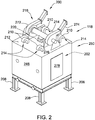
- FIG. 2 is a perspective view of an exemplary gas fuel module enclosure 118 that may be used with gas turbine 100 (shown in FIG. 1 ).
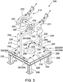
- FIG. 3 is a perspective view of an exemplary integrated ventilation and leak detection system 200 that may be used within gas fuel module enclosure 118 (shown in FIG. 1 ).
- gas fuel module enclosure 118 defines an interior chamber 202 that is sized to receive at least a portion of fuel system 116.
- enclosure 118 is sized to receive fuel piping, purge piping, and associated valves (all not shown) that facilitate channeling fuel 126 towards combustor section 108.
- a gas fuel flange may be a potential fuel leak source.
- other potential fuel leak sources may be located anywhere within fuel system 116 that is enclosed by gas fuel module enclosure 118.
- Fuel system 116 channels fuel toward combustor section 108 that enables gas turbine power system 100 to function as described herein.
- fuel system 116 may channel a fuel such as, but not limited to, butane and propane. Such fuels are generally heavier than air and will tend to accumulate at a floor 204 of enclosure 118 should a leak 206 occur within fuel system 116.
- gas fuel module enclosure 118 is generally box-shaped and includes a plurality of supports 208 that support floor 204.
- Gas fuel module enclosure 118 also includes at least one inlet vent 210 coupled to a roof 212 of enclosure 118 in flow communication with interior chamber 202. More specifically, in the exemplary embodiment, enclosure 118 includes a set of four inlet vents 210 that are generally positioned at each corner of roof 212.
- enclosure 118 may include any suitable number of inlet vents 210 each positioned in any suitable location that enables inlet vents 210 to function as described herein, for example inlet vents 210 may be coupled to a side wall of enclosure 118.
- each inlet vent 210 is J-shaped with an opening 214 that is offset from roof 212 and that faces towards roof 212 such that debris and moisture from the ambient air is restricted from entering enclosure 118.
- each inlet vent 210 has any suitable shape that enables inlet vents 210 to function as described herein.
- interior chamber 202 is also sized to receive at least a portion of integrated ventilation and leak detection system 200 therein.
- ventilation and leak detection system 200 includes a ventilation duct 216 that extends within interior chamber 202, a fan assembly 218 coupled in flow communication with ventilation duct 216, and a hazardous gas detection unit 220.
- Ventilation duct 216 includes at least one inlet end 222 positioned within a lower portion of interior chamber 202, such as adjacent to floor 204. Ventilation duct 216 further includes at least one outlet end 224 positioned proximate to roof 212 of enclosure 118, and in flow communication with detection unit 220.
- Inlet end 222 includes at least one opening 226 that is sized to enable air 228 from within interior chamber 202 to be drawn into inlet end 222 of ventilation duct 216.
- inlet and outlet ends 222 and 224 are positioned at any other location within enclosure 118 that enables ventilation and leak detection system 200 to function as described herein.
- fan assembly 218 creates a negative pressure within enclosure 118 such that air 228 within interior chamber 202 is drawn through opening 226 and into ventilation duct 216 as ventilation flow 230.
- fuel 232 is also drawn through opening 226 and into ventilation duct 216.
- such fuel 232 is entrained within ventilation flow 230.
- Ventilation flow 230 including enclosure air 228 and any entrained fuel 232, is channeled through ventilation duct 216 from inlet end 222 towards outlet end 224.
- ventilation flow 230 is channeled through detection unit 220, which detects whether fuel 232 is contained within ventilation flow 230.
- ventilation duct 216 includes a first leg 234 and an opposing second leg 236. More specifically, first leg 234 is adjacent to a wall 248 of enclosure 118, and second leg 236 is adjacent to an opposing wall 250 of enclosure 118.
- Each leg 234 and 236 is substantially T-shaped and includes a vertical member 238 and 240, respectively, and a horizontal member 242 and 244, respectively, such that horizontal members 242 and 244 extend generally parallel to floor 204, and below fuel system 116 located within interior chamber 202.
- Ventilation duct 216 also includes a cross duct 246 that couples vertical members 238 and 240 in flow communication and that forms a substantially U-shaped ventilation duct 216.
- cross duct 246 is adjacent to roof 212 to facilitate reducing its footprint (i.e. the amount of space ventilation duct 216 occupies) within interior chamber 202.
- Outlet end 224 is positioned along cross duct 246 and is coupled in flow communication with detection unit 220.
- ventilation duct 216 may have any other shape and/or structure that enables ventilation duct 216 to function as described herein.
- each horizontal member 242 and 244 includes a respective first inlet end 252 and 254 that includes a first opening 256 and 258, respectively, defined therein.
- each horizontal member 242 and 244 includes an opposite second inlet end 260 and 262, respectively, that includes a respective second opening 264 and 266.
- ventilation duct 216 includes a total of four inlet ends 222 including four total openings 226. Openings 256, 258, 264, and 266 each have any shape and/or orientation that enables ventilation and leak detection system 200 to function as described herein.
- ventilation duct 216 includes any suitable number of inlet ends 222 and openings 226 that enables ventilation duct 216 to function as described herein.
- first leg horizontal member 242 is adjacent to wall 248 and second leg horizontal member 244 is adjacent to wall 250 such that ventilation duct 216 includes openings 256, 258, 264, and 266 that are generally located at each of the four corners of floor 204.
- inlet ends 222 and openings 226 are located, with respect to floor 204, in any suitable arrangement that enables ventilation duct 216 to function as described herein.
- a location of openings 226 within a lower portion of interior chamber 202, such as adjacent to floor 204, and a location of inlet vents 210 on roof 212, facilitates circulation of enclosure air 228 throughout enclosure 118 for ventilation. More specifically, ambient air (not shown) is drawn into interior chamber 202 through inlet vents 210 coupled on roof 212 via the negative pressure induced by fan assembly 218. Enclosure air 228 flows throughout interior chamber 202 and is drawn into ventilation duct openings 226, channeled through ventilation duct 216, and returns to the ambient air via fan assembly 218.
- openings 226 within a lower section of interior chamber 202 increases a likelihood that any leaked fuel 232 is drawn into ventilation duct 216 for detection by detection unit 220.
- openings 226 and inlet vents 210 are located in any suitable location and/or orientation that enables ventilation and leak detection system 200 to function as described herein.
- a cross-sectional area of each portion of ventilation duct 216 is sized to provide a consistent ventilation flow 230 therein and to facilitate consistent ventilation within enclosure 118.
- the design of ventilation and leak detection system 200 reduces a volume of enclosure air 228 that stagnates within interior chamber 202.
- a cross-sectional area of cross duct 246 is approximately the same size as a combined cross-sectional area of first leg vertical member 238 and second leg vertical member 240, and is approximately the same size as a combined cross-sectional area of each inlet end 252, 254, 260, and 262 of horizontal members 242 and 244.
- enclosure air 228 is drawn at approximately the same rate and generally equally from all corners of interior chamber 202.
- each portion of ventilation duct 216 may have any cross-sectional area and/or shape that enables ventilation and leak detection system 200 to function as described herein.
- ventilation duct 216 also includes a middle inlet 268 extending between roof 212 and floor 204 of enclosure 118 on each respective leg 234 and 236. Middle inlet 268 further facilitates the ventilation of a middle section of interior chamber 202. Additionally or alternatively, ventilation duct 216 may include an upper inlet 270 on cross duct 246 and adjacent to roof 212. Upper inlet 270 enhances the ventilation of an upper section of interior chamber 202.
- hazardous gas detection unit 220 is coupled in flow communication with ventilation duct 216 proximate to outlet end 224 and adjacent to enclosure roof 212.
- detection unit 220 is coupled to an exterior surface of enclosure 118.
- Detection unit 220 detects fuel 232 within ventilation flow 230 that passes through before being discharged at fan assembly 218 into the ambient air. Because detection unit 220 is at outlet end 224, detection unit 220 can detect fuel leaks adjacent to any of inlet ends 222.
- Detection unit 220 may be any fuel detection mechanism that enables ventilation and leak detection system 200 to function as described herein.
- detection unit 220 includes at least one sample probe 276 that is coupled in flow communication with a sensor system 278. Sample probes 276 are positioned adjacent to outlet end 224 and within ventilation flow 230. Sample probes 276 include a nozzle that extracts a small mass of air from ventilation flow 230 and channels the air to sensor system 278.
- Sensor system 278 is positioned at an exterior wall of enclosure 118 and includes, for example, but not by way of limitation, at least one of infrared, catalytic bead, semiconductor, and oxidation sensor systems, which facilitate detecting fuel 232 within the air extracted by sample probes 276.
- detection unit 220 including sample probes 276 and sensor system 278, may be positioned at any other location that enables ventilation and leak detection system 200 to function as described herein.
- detection unit 220 determines an occurrence of potential fuel leaks when a concentration of fuel 232 in ventilation flow 230 is above a predetermined threshold. For example, if detection unit 220 determines that a lower explosive limit for fuel 232 is exceeded within interior chamber 202, then a signal is sent to operations control (not shown) and gas fuel module 118 is shut down or fuel system 116 is switched to another fuel source.
- detection unit 220 determines that a concentration of fuel 232 is greater than about 18% of the lower explosive limit for fuel 232, then a first alarm level signal is sent to operations control, and if detection unit 220 determines that a concentration of fuel 232 is greater than about 8% of the lower explosive limit for fuel 232, then a second alarm level signal is sent to operations control. In alternative embodiments, detection unit 220 may trigger any suitable number of alarm level signals in response to any suitable corresponding detected concentration of fuel 232.
- fan assembly 218 includes two fans 272 and 274 in flow communication with ventilation duct 216 and detection unit 220.
- each fan 272 and 274 is downstream of ventilation duct 216 and coupled to an exterior surface of roof 212.
- two fans 272 and 274 are provided such that one can be in operation and the other is reserved for back up, thereby facilitating constant ventilation of enclosure 118.
- fan assembly 218 includes any suitable number of fans located at any suitable position that enables system 200 to function as described herein. In operation, fan assembly 218 creates a negative pressure within enclosure 118 such that ambient air is drawn into interior chamber 202 via inlet vents 210, enclosure air 228 is drawn into ventilation duct 216, and ventilation flow 230 is exhausted back out to the ambient air.
- exemplary method 400 of assembling an integrated ventilation and leak detection system is illustrated in the flow diagram of FIG. 4 .
- exemplary method 400 includes coupling 402 a ventilation duct, such as ventilation duct 216, within an interior chamber defined in an enclosure, such as interior chamber 202 of gas fuel module enclosure 118.
- method 400 includes coupling 404 a detection unit, such as detection unit 220, in flow communication with the ventilation duct.
- method 400 includes coupling 406 a fan assembly, such as fan assembly 218, in flow communication with the ventilation duct.
- method 400 includes coupling 408 the detection unit that is configured to determine a concentration of the fuel, such as fuel 232, and to signal a potential fuel leak.
- method 400 includes positioning 410 a plurality of inlet ends, such as inlet ends 252, 254, 260, and 262, adjacent to a respective corner of the interior chamber.
- method 400 further includes coupling 412 at least one inlet vent, such as inlet vent 210, in flow communication with the interior chamber.
- Exemplary embodiments of integrated ventilation and leak detection systems and methods are described above in detail and provide a system that ventilates an enclosure as well as detecting potential fuel leaks.
- the embodiments described herein include a ventilation duct that is sized to enable air and fuel to be drawn into the duct and exhausted, while providing ventilation to the enclosure.
- a detection unit is proximate to an outlet of the ventilation duct to detect fuel entrained within the ventilation flow.
- fuels used in gas turbines are heavier than air
- the ventilation duct includes at least one inlet end positioned within a lower portion of the enclosure such that potential fuel leaks can be drawn into the ventilation duct and channeled through the detection unit.
- the integrated ventilation and leak detection system facilitates reducing equipment, installation, and maintenance costs by combining what are typically two separate systems, a ventilation system and a hazardous gas detection system. Furthermore, the system described herein maintains the reliability of gas leak detection for heavy gas fuels in a single integrated system with enclosure ventilation.
- An exemplary technical effect of the methods, systems, and apparatus described herein includes at least one of: (a) simplify an integrated ventilation and leak detection system; (b) maintain ventilation within an enclosure containing heavy gas fuels; (c) maintain reliability for gas leak detection; (d) reduce equipment costs; (e) reduce installation costs; and (f) reduce maintenance costs.
Landscapes
- Engineering & Computer Science (AREA)
- Chemical & Material Sciences (AREA)
- Combustion & Propulsion (AREA)
- Mechanical Engineering (AREA)
- General Engineering & Computer Science (AREA)
- Physics & Mathematics (AREA)
- General Physics & Mathematics (AREA)
- Examining Or Testing Airtightness (AREA)
- Investigating Or Analysing Materials By Optical Means (AREA)
Claims (14)
- Belüftungs- und Leckdetektionssystem (200) zur Verwendung in einem Gehäuse (118), wobei das System umfasst:einen Lüftungskanal (216), der sich bei Verwendung mindestens teilweise durch eine innere Kammer (202) erstreckt, die in dem Gehäuse definiert ist, wobei der Lüftungskanal eine Vielzahl von Einlassenden (252, 254, 260, 262), die innerhalb eines unteren Abschnitts (204) der inneren Kammer positioniert sind, und ein Auslassende (224) umfasst, wobei jedes der Vielzahl von Einlassenden bei Verwendung benachbart zu einer jeweiligen Ecke der inneren Kammer (202) ist und mindestens eine Öffnung (256, 258, 264, 266) umfasst, die darin definiert und dimensioniert ist, um zu ermöglichen, dass Luft (228) und Brennstoff (232) in dem Gehäuse in den Lüftungskanal gesogen werden, um das Gehäuse zu belüften; undeine Detektionseinheit (220), die nahe dem Auslassende in Strömungsverbindung mit dem Lüftungskanal gekoppelt ist, um Brennstoff zu erkennen, der in der Strömung (230), die in den Lüftungskanal gesogen wird, mitgeführt wird.
- System (200) nach Anspruch 1, ferner umfassend eine Gebläseanordnung (218), die in Strömungsverbindung mit dem Lüftungskanal gekoppelt ist, wobei die Gebläseanordnung konfiguriert ist, um:einen Unterdruck in dem Gehäuse zu erzeugen, um die Strömung in den Lüftungskanal zu saugen; unddie Strömung in dem Lüftungskanal an eine außen liegende Stelle abzugeben.
- System (200) nach Anspruch 2, wobei die Gebläseanordnung ein erstes Gebläse (272) und ein zweites Gebläse (274) umfasst, wobei jedes Gebläse mit einem Gehäusedach (212) gekoppelt ist.
- System (200) nach Anspruch 1, 2 oder 3, wobei die Detektionseinheit in der Lage ist:eine Konzentration des in der Strömung mitgeführten Brennstoffs zu bestimmen; undein potentielles Brennstoffleck zu signalisieren, wenn die Brennstoffkonzentration größer als ein vorbestimmter Schwellenwert ist.
- System (200) nach einem der Ansprüche 1 bis 4, wobei die Detektionseinheit einen Infrarotsensor umfasst.
- System (200) nach einem der Ansprüche 1 bis 4, wobei die Detektionseinheit einen katalytischen Sensor umfasst.
- System (200) nach einem der vorstehenden Ansprüche, wobei mindestens ein Abschnitt des Lüftungskanals nahe dem mindestens einen Einlassende sich im Wesentlichen parallel zu einem Boden des Gehäuses erstreckt.
- System (200) nach einem der vorstehenden Ansprüche, wobei der Lüftungskanal ferner mindestens einen mittleren Einlass (268) umfasst, der sich in einem mittleren Abschnitt der inneren Kammer erstreckt.
- System (200) nach einem der vorstehenden Ansprüche, wobei der Lüftungskanal ferner mindestens einen oberen Einlass (270) umfasst, der innerhalb eines oberen Abschnitts der inneren Kammer definiert ist.
- System (200) nach einem der vorstehenden Ansprüche, ferner umfassend mindestens einen Einlassschlitz (210) in Strömungsverbindung mit der inneren Kammer, wobei der mindestens eine Einlassschlitz konfiguriert ist, um Umgebungsluft in die innere Kammer zu leiten.
- Gasbrennstoffmodul (118), umfassend:ein Belüftungs- und Leckdetektionssystem (200) nach Anspruch 1; undein Gasbrennstoffmodulgehäuse (118), das eine innere Kammer (202) definiert, wobei die innere Kammer (202) des Gasbrennstoffmodulgehäuses (118) die innere Kammer (202) des Belüftungs- und Leckdetektionssystems (200) definiert.
- Gasbrennstoffmodul (118) nach Anspruch 11, ferner umfassend eine Gebläseanordnung (218), die in Strömungsverbindung mit dem Lüftungskanal gekoppelt ist, wobei die Gebläseanordnung konfiguriert ist, um:einen Unterdruck innerhalb des Gehäuses zu erzeugen, um die Strömung in den Lüftungskanal zu saugen; unddie Strömung in dem Lüftungskanal an eine außen liegende Stelle abzugeben.
- Gasbrennstoffmodul (118) nach Anspruch 11 oder 12, wobei die Detektionseinheit in der Lage ist:eine Konzentration des in der Strömung mitgeführten Brennstoffs zu bestimmen; undein potentielles Brennstoffleck zu signalisieren, wenn die Brennstoffkonzentration größer als ein vorbestimmter Schwellenwert ist.
- Gasbrennstoffmodul (118) nach Anspruch 12 oder 13, ferner umfassend mindestens einen Einlassschlitz (210), der mit einem Gehäusedach (212) gekoppelt ist, das in Strömungsverbindung mit der inneren Kammer steht, wobei der mindestens eine Einlassschlitz in der Lage ist, Umgebungsluft in die innere Kammer zu leiten.
Applications Claiming Priority (1)
| Application Number | Priority Date | Filing Date | Title |
|---|---|---|---|
| US15/155,928 US10101238B2 (en) | 2016-05-16 | 2016-05-16 | Integrated ventilation and leak detection system and method of assembly |
Publications (2)
| Publication Number | Publication Date |
|---|---|
| EP3246556A1 EP3246556A1 (de) | 2017-11-22 |
| EP3246556B1 true EP3246556B1 (de) | 2020-02-26 |
Family
ID=58709268
Family Applications (1)
| Application Number | Title | Priority Date | Filing Date |
|---|---|---|---|
| EP17170593.2A Active EP3246556B1 (de) | 2016-05-16 | 2017-05-11 | Belüftungs- und leckdetektionssystem |
Country Status (5)
| Country | Link |
|---|---|
| US (1) | US10101238B2 (de) |
| EP (1) | EP3246556B1 (de) |
| JP (1) | JP7038490B2 (de) |
| KR (2) | KR20170129064A (de) |
| CN (1) | CN107448974B (de) |
Families Citing this family (11)
| Publication number | Priority date | Publication date | Assignee | Title |
|---|---|---|---|---|
| US12198215B2 (en) | 2014-05-28 | 2025-01-14 | Mitek Systems, Inc. | Self-sovereign identity systems and methods for identification documents |
| US11461567B2 (en) | 2014-05-28 | 2022-10-04 | Mitek Systems, Inc. | Systems and methods of identification verification using hybrid near-field communication and optical authentication |
| US11640582B2 (en) * | 2014-05-28 | 2023-05-02 | Mitek Systems, Inc. | Alignment of antennas on near field communication devices for communication |
| ES2980278T3 (es) * | 2018-11-09 | 2024-09-30 | Carrier Corp | Armario de ventas refrigerado |
| JP2022172445A (ja) | 2021-05-04 | 2022-11-16 | ゼネラル・エレクトリック・カンパニイ | ガスタービン区画内の有害な燃料ガス漏れの効率的な検出のためのシステムおよび方法 |
| CN113062880B (zh) * | 2021-05-19 | 2023-07-25 | 中电(四会)热电有限责任公司 | 一种燃机罩壳风机的节能控制方法 |
| US11846568B2 (en) | 2021-06-09 | 2023-12-19 | Pratt & Whitney Canada Corp. | Leak detection for pressurized fluid systems |
| US12000758B2 (en) | 2021-06-09 | 2024-06-04 | Pratt & Whitney Canada Corp. | Leak detection for pressurized fluid systems |
| US11773781B2 (en) * | 2021-06-11 | 2023-10-03 | Pratt & Whitney Canada Corp. | Means for handling gaseous fuel |
| US12305576B2 (en) | 2022-12-29 | 2025-05-20 | Ge Vernova Infrastructure Technology Llc | Radiation shield for a gaseous fuel circuit |
| US12129799B2 (en) * | 2022-12-29 | 2024-10-29 | Ge Infrastructure Technology Llc | Thermal radiation shield for a gaseous fuel circuit |
Family Cites Families (35)
| Publication number | Priority date | Publication date | Assignee | Title |
|---|---|---|---|---|
| US4491779A (en) | 1983-10-12 | 1985-01-01 | General Motors Corporation | Motor vehicle electrical system |
| JPS6291830A (ja) * | 1985-10-18 | 1987-04-27 | Ohbayashigumi Ltd | 気密保持室内における気密性能の評価方法 |
| US5637788A (en) | 1995-08-03 | 1997-06-10 | Motorola Inc. | Apparatus and method of detecting a leak in an evaporative emissions system |
| US6360741B2 (en) | 1998-11-25 | 2002-03-26 | Respironics, Inc. | Pressure support system with a low leak alarm and method of using same |
| US6357221B1 (en) * | 2000-07-21 | 2002-03-19 | General Electric Company | Ventilation for an enclosure of a gas turbine and related method |
| JP2002058950A (ja) * | 2000-08-22 | 2002-02-26 | Hitachi Plant Eng & Constr Co Ltd | 有害ガス換気吸収装置 |
| US6578361B1 (en) * | 2001-08-30 | 2003-06-17 | General Electric Co. | Methods and apparatus for determining engine cavity leakage |
| JP2003107073A (ja) * | 2001-09-28 | 2003-04-09 | Mitsubishi Heavy Ind Ltd | ガス検知装置及び石炭ガス化複合発電プラント |
| US6626133B2 (en) * | 2002-02-19 | 2003-09-30 | Edwards Systems Technology, Inc | Explosion protection sensor for gas appliances |
| US7107820B2 (en) | 2003-05-02 | 2006-09-19 | Praxair S.T. Technology, Inc. | Integrated gas supply and leak detection system |
| WO2005047843A1 (en) | 2003-11-17 | 2005-05-26 | The Refrigerant Oil Company (Singapore) Pte Ltd | Method and system for leak detection |
| EP1961439B1 (de) | 2007-02-23 | 2009-12-16 | General Electric Company | Beatmungssystem für die Anästhesie und Verfahren zur Leckerkennung bei dem Beatmungssystem für die Anästhesie |
| EP2168623B1 (de) | 2008-09-26 | 2011-09-21 | General Electric Company | Anordnung zur Detektion eines Lecks in einem Anästhesiesystem |
| US8240427B2 (en) * | 2008-10-01 | 2012-08-14 | General Electric Company | Sound attenuation systems and methods |
| CN202133061U (zh) * | 2008-11-26 | 2012-02-01 | 德尔福技术有限公司 | 制冷剂泄漏探测系统及其制冷剂传感器组件 |
| US20100326171A1 (en) | 2009-06-26 | 2010-12-30 | Gene Stauffer | Smoke generation and leak detection system |
| WO2014036561A2 (en) | 2012-08-31 | 2014-03-06 | Holtec International, Inc. | System and method for storing and leak testing a radioactive materials storage canister |
| US20120090383A1 (en) | 2010-10-14 | 2012-04-19 | Audra Lopez | System and method for detecting a refrigerant leak and chemicals produced as a result of heating of the refrigerant |
| CN201951709U (zh) * | 2010-11-07 | 2011-08-31 | 沪东中华造船(集团)有限公司 | 一种双燃料lng船燃气输送管路的通风系统 |
| US8922379B1 (en) | 2011-07-05 | 2014-12-30 | John Meyer | Centralized water leak detection system |
| US20130125626A1 (en) | 2011-11-17 | 2013-05-23 | John L. PRITCHETT | Leak detection apparatus, system, and method |
| US9038441B2 (en) | 2012-01-20 | 2015-05-26 | TLI Enterprises, Inc. | High speed helium leak detection system and method |
| JP2013174222A (ja) * | 2012-02-27 | 2013-09-05 | Toshiba Corp | 換気システムおよびその運用方法 |
| US9498590B2 (en) | 2012-03-05 | 2016-11-22 | Sonarmed, Inc. | Leak detection system and method for tube or catheter placement |
| US20140080403A1 (en) | 2012-09-14 | 2014-03-20 | General Electric Company | Methods and system design for providing leak detection of volatile liquid hydrocarbon vapors |
| US9382843B2 (en) * | 2012-10-08 | 2016-07-05 | General Electric Company | Flow balancing ventilation system and method of balancing a flow |
| US9239008B2 (en) * | 2012-10-16 | 2016-01-19 | General Electric Company | Turbine leak detection system |
| US9739248B2 (en) | 2013-03-15 | 2017-08-22 | Ford Global Technologies, Llc | Fuel system leak detection using passive valves |
| US9322342B2 (en) | 2013-04-17 | 2016-04-26 | Ford Global Technologies, Llc | Hybrid vehicle fuel system leak detection |
| DE102013209438A1 (de) * | 2013-05-22 | 2014-11-27 | Inficon Gmbh | Schnüffellecksucher mit nanoporöser Membrane |
| PL405434A1 (pl) * | 2013-09-24 | 2015-03-30 | General Electric Company | Układ i sposób zapewniania zasadniczo jednorodnego przepływu powietrza wentylacyjnego wewnątrz obudowy silnika turbospalinowego |
| FR3016948B1 (fr) | 2014-01-24 | 2016-12-09 | Airbus Operations Sas | Dispositif d'attache de cordons de detection, notamment pour un systeme de detection de fuites et de surchauffe sur un conduit de gaz dans un aeronef |
| US9822737B2 (en) | 2014-04-08 | 2017-11-21 | Ford Global Technologies, Llc | System and methods for a leak check module comprising a reversible vacuum pump |
| US9506835B2 (en) * | 2014-04-23 | 2016-11-29 | General Electric Company | Fuel leak detection system for use in a turbine enclosure |
| US20150360860A1 (en) * | 2014-06-12 | 2015-12-17 | Derrick Ernest Hilton | Cylinder ventilation device |
-
2016
- 2016-05-16 US US15/155,928 patent/US10101238B2/en active Active
-
2017
- 2017-05-11 JP JP2017094330A patent/JP7038490B2/ja active Active
- 2017-05-11 EP EP17170593.2A patent/EP3246556B1/de active Active
- 2017-05-15 KR KR1020170060033A patent/KR20170129064A/ko not_active Ceased
- 2017-05-16 CN CN201710346157.3A patent/CN107448974B/zh active Active
-
2023
- 2023-04-10 KR KR1020230046835A patent/KR20230053570A/ko not_active Ceased
Non-Patent Citations (1)
| Title |
|---|
| None * |
Also Published As
| Publication number | Publication date |
|---|---|
| CN107448974A (zh) | 2017-12-08 |
| EP3246556A1 (de) | 2017-11-22 |
| KR20170129064A (ko) | 2017-11-24 |
| JP7038490B2 (ja) | 2022-03-18 |
| CN107448974B (zh) | 2021-03-23 |
| US20170328805A1 (en) | 2017-11-16 |
| US10101238B2 (en) | 2018-10-16 |
| KR20230053570A (ko) | 2023-04-21 |
| JP2017207064A (ja) | 2017-11-24 |
Similar Documents
| Publication | Publication Date | Title |
|---|---|---|
| EP3246556B1 (de) | Belüftungs- und leckdetektionssystem | |
| EP3165295B1 (de) | Gasakkumulationsdetektion und belüftung in einem gasturbinengehäuse | |
| US9506835B2 (en) | Fuel leak detection system for use in a turbine enclosure | |
| US20020127446A1 (en) | Fuel cell generation system and method | |
| CN107387265A (zh) | 高压燃气双壁管通风系统 | |
| US20200173366A1 (en) | Liquid fuel leak detection system and related method | |
| JP2006253020A (ja) | 燃料電池発電装置及び吸排気装置 | |
| US12202622B2 (en) | Means for handling gaseous fuel | |
| US12305575B2 (en) | Means for handling gaseous fuel | |
| US12399093B2 (en) | Test chamber and method | |
| JP3432575B2 (ja) | 燃料電池発電設備 | |
| CN105317557A (zh) | 用于利用燃气涡轮机室通风排放空气的系统和方法 | |
| US20140080403A1 (en) | Methods and system design for providing leak detection of volatile liquid hydrocarbon vapors | |
| CN120604025A (zh) | 燃气涡轮机组通风系统和用于对燃气涡轮机组进行通风的方法 | |
| Oh et al. | Numerical assessment of the effect of ventilation capability of kitchen hoods depending on operating conditions, design parameters, and installation location | |
| US20240229718A9 (en) | Gas turbine fire detection system including cooling system upstream of aspirating smoke detector, and related method | |
| US20220397063A1 (en) | Means for handling gaseous fuel | |
| US10578323B2 (en) | Systems for dehumidifying air and methods of assembling the same | |
| JP2015031287A (ja) | エンクロージャのための空気撹乱システム | |
| JP2006046766A (ja) | 排気システム及び排気方法 | |
| RU158471U1 (ru) | Блок силовой газоперекачивающего агрегата | |
| CN119481167A (zh) | 一种燃料电池发动机通风系统 | |
| Bertotto et al. | ISS node 2 environmental control design | |
| IT202100000395A1 (it) | Dispositivo di contenimento per sistemi a celle a combustibile. | |
| TH69177B (th) | ชุดเครื่องปรับอากาศ |
Legal Events
| Date | Code | Title | Description |
|---|---|---|---|
| PUAI | Public reference made under article 153(3) epc to a published international application that has entered the european phase |
Free format text: ORIGINAL CODE: 0009012 |
|
| STAA | Information on the status of an ep patent application or granted ep patent |
Free format text: STATUS: THE APPLICATION HAS BEEN PUBLISHED |
|
| AK | Designated contracting states |
Kind code of ref document: A1 Designated state(s): AL AT BE BG CH CY CZ DE DK EE ES FI FR GB GR HR HU IE IS IT LI LT LU LV MC MK MT NL NO PL PT RO RS SE SI SK SM TR |
|
| AX | Request for extension of the european patent |
Extension state: BA ME |
|
| STAA | Information on the status of an ep patent application or granted ep patent |
Free format text: STATUS: REQUEST FOR EXAMINATION WAS MADE |
|
| 17P | Request for examination filed |
Effective date: 20180522 |
|
| RBV | Designated contracting states (corrected) |
Designated state(s): AL AT BE BG CH CY CZ DE DK EE ES FI FR GB GR HR HU IE IS IT LI LT LU LV MC MK MT NL NO PL PT RO RS SE SI SK SM TR |
|
| GRAP | Despatch of communication of intention to grant a patent |
Free format text: ORIGINAL CODE: EPIDOSNIGR1 |
|
| STAA | Information on the status of an ep patent application or granted ep patent |
Free format text: STATUS: GRANT OF PATENT IS INTENDED |
|
| RIC1 | Information provided on ipc code assigned before grant |
Ipc: F01D 21/00 20060101ALI20190814BHEP Ipc: G01M 3/04 20060101ALI20190814BHEP Ipc: F02C 7/20 20060101ALI20190814BHEP Ipc: G01M 3/02 20060101ALI20190814BHEP Ipc: F02K 9/38 20060101AFI20190814BHEP |
|
| INTG | Intention to grant announced |
Effective date: 20190913 |
|
| GRAS | Grant fee paid |
Free format text: ORIGINAL CODE: EPIDOSNIGR3 |
|
| GRAA | (expected) grant |
Free format text: ORIGINAL CODE: 0009210 |
|
| STAA | Information on the status of an ep patent application or granted ep patent |
Free format text: STATUS: THE PATENT HAS BEEN GRANTED |
|
| AK | Designated contracting states |
Kind code of ref document: B1 Designated state(s): AL AT BE BG CH CY CZ DE DK EE ES FI FR GB GR HR HU IE IS IT LI LT LU LV MC MK MT NL NO PL PT RO RS SE SI SK SM TR |
|
| REG | Reference to a national code |
Ref country code: GB Ref legal event code: FG4D |
|
| REG | Reference to a national code |
Ref country code: CH Ref legal event code: EP |
|
| REG | Reference to a national code |
Ref country code: AT Ref legal event code: REF Ref document number: 1237925 Country of ref document: AT Kind code of ref document: T Effective date: 20200315 |
|
| REG | Reference to a national code |
Ref country code: IE Ref legal event code: FG4D |
|
| REG | Reference to a national code |
Ref country code: DE Ref legal event code: R096 Ref document number: 602017012131 Country of ref document: DE |
|
| PG25 | Lapsed in a contracting state [announced via postgrant information from national office to epo] |
Ref country code: NO Free format text: LAPSE BECAUSE OF FAILURE TO SUBMIT A TRANSLATION OF THE DESCRIPTION OR TO PAY THE FEE WITHIN THE PRESCRIBED TIME-LIMIT Effective date: 20200526 Ref country code: FI Free format text: LAPSE BECAUSE OF FAILURE TO SUBMIT A TRANSLATION OF THE DESCRIPTION OR TO PAY THE FEE WITHIN THE PRESCRIBED TIME-LIMIT Effective date: 20200226 Ref country code: RS Free format text: LAPSE BECAUSE OF FAILURE TO SUBMIT A TRANSLATION OF THE DESCRIPTION OR TO PAY THE FEE WITHIN THE PRESCRIBED TIME-LIMIT Effective date: 20200226 |
|
| REG | Reference to a national code |
Ref country code: NL Ref legal event code: MP Effective date: 20200226 |
|
| REG | Reference to a national code |
Ref country code: LT Ref legal event code: MG4D |
|
| PG25 | Lapsed in a contracting state [announced via postgrant information from national office to epo] |
Ref country code: IS Free format text: LAPSE BECAUSE OF FAILURE TO SUBMIT A TRANSLATION OF THE DESCRIPTION OR TO PAY THE FEE WITHIN THE PRESCRIBED TIME-LIMIT Effective date: 20200626 Ref country code: GR Free format text: LAPSE BECAUSE OF FAILURE TO SUBMIT A TRANSLATION OF THE DESCRIPTION OR TO PAY THE FEE WITHIN THE PRESCRIBED TIME-LIMIT Effective date: 20200527 Ref country code: LV Free format text: LAPSE BECAUSE OF FAILURE TO SUBMIT A TRANSLATION OF THE DESCRIPTION OR TO PAY THE FEE WITHIN THE PRESCRIBED TIME-LIMIT Effective date: 20200226 Ref country code: SE Free format text: LAPSE BECAUSE OF FAILURE TO SUBMIT A TRANSLATION OF THE DESCRIPTION OR TO PAY THE FEE WITHIN THE PRESCRIBED TIME-LIMIT Effective date: 20200226 Ref country code: HR Free format text: LAPSE BECAUSE OF FAILURE TO SUBMIT A TRANSLATION OF THE DESCRIPTION OR TO PAY THE FEE WITHIN THE PRESCRIBED TIME-LIMIT Effective date: 20200226 Ref country code: BG Free format text: LAPSE BECAUSE OF FAILURE TO SUBMIT A TRANSLATION OF THE DESCRIPTION OR TO PAY THE FEE WITHIN THE PRESCRIBED TIME-LIMIT Effective date: 20200526 |
|
| PG25 | Lapsed in a contracting state [announced via postgrant information from national office to epo] |
Ref country code: NL Free format text: LAPSE BECAUSE OF FAILURE TO SUBMIT A TRANSLATION OF THE DESCRIPTION OR TO PAY THE FEE WITHIN THE PRESCRIBED TIME-LIMIT Effective date: 20200226 |
|
| PG25 | Lapsed in a contracting state [announced via postgrant information from national office to epo] |
Ref country code: ES Free format text: LAPSE BECAUSE OF FAILURE TO SUBMIT A TRANSLATION OF THE DESCRIPTION OR TO PAY THE FEE WITHIN THE PRESCRIBED TIME-LIMIT Effective date: 20200226 Ref country code: PT Free format text: LAPSE BECAUSE OF FAILURE TO SUBMIT A TRANSLATION OF THE DESCRIPTION OR TO PAY THE FEE WITHIN THE PRESCRIBED TIME-LIMIT Effective date: 20200719 Ref country code: DK Free format text: LAPSE BECAUSE OF FAILURE TO SUBMIT A TRANSLATION OF THE DESCRIPTION OR TO PAY THE FEE WITHIN THE PRESCRIBED TIME-LIMIT Effective date: 20200226 Ref country code: LT Free format text: LAPSE BECAUSE OF FAILURE TO SUBMIT A TRANSLATION OF THE DESCRIPTION OR TO PAY THE FEE WITHIN THE PRESCRIBED TIME-LIMIT Effective date: 20200226 Ref country code: SM Free format text: LAPSE BECAUSE OF FAILURE TO SUBMIT A TRANSLATION OF THE DESCRIPTION OR TO PAY THE FEE WITHIN THE PRESCRIBED TIME-LIMIT Effective date: 20200226 Ref country code: CZ Free format text: LAPSE BECAUSE OF FAILURE TO SUBMIT A TRANSLATION OF THE DESCRIPTION OR TO PAY THE FEE WITHIN THE PRESCRIBED TIME-LIMIT Effective date: 20200226 Ref country code: EE Free format text: LAPSE BECAUSE OF FAILURE TO SUBMIT A TRANSLATION OF THE DESCRIPTION OR TO PAY THE FEE WITHIN THE PRESCRIBED TIME-LIMIT Effective date: 20200226 Ref country code: RO Free format text: LAPSE BECAUSE OF FAILURE TO SUBMIT A TRANSLATION OF THE DESCRIPTION OR TO PAY THE FEE WITHIN THE PRESCRIBED TIME-LIMIT Effective date: 20200226 Ref country code: SK Free format text: LAPSE BECAUSE OF FAILURE TO SUBMIT A TRANSLATION OF THE DESCRIPTION OR TO PAY THE FEE WITHIN THE PRESCRIBED TIME-LIMIT Effective date: 20200226 |
|
| REG | Reference to a national code |
Ref country code: AT Ref legal event code: MK05 Ref document number: 1237925 Country of ref document: AT Kind code of ref document: T Effective date: 20200226 |
|
| REG | Reference to a national code |
Ref country code: DE Ref legal event code: R097 Ref document number: 602017012131 Country of ref document: DE |
|
| PLBE | No opposition filed within time limit |
Free format text: ORIGINAL CODE: 0009261 |
|
| STAA | Information on the status of an ep patent application or granted ep patent |
Free format text: STATUS: NO OPPOSITION FILED WITHIN TIME LIMIT |
|
| PG25 | Lapsed in a contracting state [announced via postgrant information from national office to epo] |
Ref country code: LI Free format text: LAPSE BECAUSE OF NON-PAYMENT OF DUE FEES Effective date: 20200531 Ref country code: IT Free format text: LAPSE BECAUSE OF FAILURE TO SUBMIT A TRANSLATION OF THE DESCRIPTION OR TO PAY THE FEE WITHIN THE PRESCRIBED TIME-LIMIT Effective date: 20200226 Ref country code: CH Free format text: LAPSE BECAUSE OF NON-PAYMENT OF DUE FEES Effective date: 20200531 Ref country code: AT Free format text: LAPSE BECAUSE OF FAILURE TO SUBMIT A TRANSLATION OF THE DESCRIPTION OR TO PAY THE FEE WITHIN THE PRESCRIBED TIME-LIMIT Effective date: 20200226 Ref country code: MC Free format text: LAPSE BECAUSE OF FAILURE TO SUBMIT A TRANSLATION OF THE DESCRIPTION OR TO PAY THE FEE WITHIN THE PRESCRIBED TIME-LIMIT Effective date: 20200226 |
|
| 26N | No opposition filed |
Effective date: 20201127 |
|
| PG25 | Lapsed in a contracting state [announced via postgrant information from national office to epo] |
Ref country code: PL Free format text: LAPSE BECAUSE OF FAILURE TO SUBMIT A TRANSLATION OF THE DESCRIPTION OR TO PAY THE FEE WITHIN THE PRESCRIBED TIME-LIMIT Effective date: 20200226 Ref country code: SI Free format text: LAPSE BECAUSE OF FAILURE TO SUBMIT A TRANSLATION OF THE DESCRIPTION OR TO PAY THE FEE WITHIN THE PRESCRIBED TIME-LIMIT Effective date: 20200226 |
|
| REG | Reference to a national code |
Ref country code: BE Ref legal event code: MM Effective date: 20200531 |
|
| PG25 | Lapsed in a contracting state [announced via postgrant information from national office to epo] |
Ref country code: LU Free format text: LAPSE BECAUSE OF NON-PAYMENT OF DUE FEES Effective date: 20200511 |
|
| PG25 | Lapsed in a contracting state [announced via postgrant information from national office to epo] |
Ref country code: IE Free format text: LAPSE BECAUSE OF NON-PAYMENT OF DUE FEES Effective date: 20200511 Ref country code: FR Free format text: LAPSE BECAUSE OF NON-PAYMENT OF DUE FEES Effective date: 20200531 |
|
| PG25 | Lapsed in a contracting state [announced via postgrant information from national office to epo] |
Ref country code: BE Free format text: LAPSE BECAUSE OF NON-PAYMENT OF DUE FEES Effective date: 20200531 |
|
| GBPC | Gb: european patent ceased through non-payment of renewal fee |
Effective date: 20210511 |
|
| PG25 | Lapsed in a contracting state [announced via postgrant information from national office to epo] |
Ref country code: GB Free format text: LAPSE BECAUSE OF NON-PAYMENT OF DUE FEES Effective date: 20210511 |
|
| PG25 | Lapsed in a contracting state [announced via postgrant information from national office to epo] |
Ref country code: TR Free format text: LAPSE BECAUSE OF FAILURE TO SUBMIT A TRANSLATION OF THE DESCRIPTION OR TO PAY THE FEE WITHIN THE PRESCRIBED TIME-LIMIT Effective date: 20200226 Ref country code: MT Free format text: LAPSE BECAUSE OF FAILURE TO SUBMIT A TRANSLATION OF THE DESCRIPTION OR TO PAY THE FEE WITHIN THE PRESCRIBED TIME-LIMIT Effective date: 20200226 Ref country code: CY Free format text: LAPSE BECAUSE OF FAILURE TO SUBMIT A TRANSLATION OF THE DESCRIPTION OR TO PAY THE FEE WITHIN THE PRESCRIBED TIME-LIMIT Effective date: 20200226 |
|
| PG25 | Lapsed in a contracting state [announced via postgrant information from national office to epo] |
Ref country code: MK Free format text: LAPSE BECAUSE OF FAILURE TO SUBMIT A TRANSLATION OF THE DESCRIPTION OR TO PAY THE FEE WITHIN THE PRESCRIBED TIME-LIMIT Effective date: 20200226 Ref country code: AL Free format text: LAPSE BECAUSE OF FAILURE TO SUBMIT A TRANSLATION OF THE DESCRIPTION OR TO PAY THE FEE WITHIN THE PRESCRIBED TIME-LIMIT Effective date: 20200226 |
|
| REG | Reference to a national code |
Ref country code: DE Ref legal event code: R082 Ref document number: 602017012131 Country of ref document: DE Ref country code: DE Ref legal event code: R081 Ref document number: 602017012131 Country of ref document: DE Owner name: GENERAL ELECTRIC TECHNOLOGY GMBH, CH Free format text: FORMER OWNER: GENERAL ELECTRIC COMPANY, SCHENECTADY, NY, US |
|
| PGFP | Annual fee paid to national office [announced via postgrant information from national office to epo] |
Ref country code: DE Payment date: 20250423 Year of fee payment: 9 |