EP3246771A1 - Verfahren zum betreiben eines redundanten automatisierungssystems - Google Patents
Verfahren zum betreiben eines redundanten automatisierungssystems Download PDFInfo
- Publication number
- EP3246771A1 EP3246771A1 EP16169894.9A EP16169894A EP3246771A1 EP 3246771 A1 EP3246771 A1 EP 3246771A1 EP 16169894 A EP16169894 A EP 16169894A EP 3246771 A1 EP3246771 A1 EP 3246771A1
- Authority
- EP
- European Patent Office
- Prior art keywords
- reserve
- master
- automation system
- process control
- redundant
- Prior art date
- Legal status (The legal status is an assumption and is not a legal conclusion. Google has not performed a legal analysis and makes no representation as to the accuracy of the status listed.)
- Granted
Links
Images

Classifications
-
- G—PHYSICS
- G05—CONTROLLING; REGULATING
- G05B—CONTROL OR REGULATING SYSTEMS IN GENERAL; FUNCTIONAL ELEMENTS OF SUCH SYSTEMS; MONITORING OR TESTING ARRANGEMENTS FOR SUCH SYSTEMS OR ELEMENTS
- G05B23/00—Testing or monitoring of control systems or parts thereof
- G05B23/02—Electric testing or monitoring
- G05B23/0205—Electric testing or monitoring by means of a monitoring system capable of detecting and responding to faults
- G05B23/0259—Electric testing or monitoring by means of a monitoring system capable of detecting and responding to faults characterized by the response to fault detection
- G05B23/0286—Modifications to the monitored process, e.g. stopping operation or adapting control
- G05B23/0289—Reconfiguration to prevent failure, e.g. usually as a reaction to incipient failure detection
-
- G—PHYSICS
- G05—CONTROLLING; REGULATING
- G05B—CONTROL OR REGULATING SYSTEMS IN GENERAL; FUNCTIONAL ELEMENTS OF SUCH SYSTEMS; MONITORING OR TESTING ARRANGEMENTS FOR SUCH SYSTEMS OR ELEMENTS
- G05B9/00—Safety arrangements
- G05B9/02—Safety arrangements electric
- G05B9/03—Safety arrangements electric with multiple-channel loop, i.e. redundant control systems
-
- G—PHYSICS
- G05—CONTROLLING; REGULATING
- G05B—CONTROL OR REGULATING SYSTEMS IN GENERAL; FUNCTIONAL ELEMENTS OF SUCH SYSTEMS; MONITORING OR TESTING ARRANGEMENTS FOR SUCH SYSTEMS OR ELEMENTS
- G05B19/00—Program-control systems
- G05B19/02—Program-control systems electric
- G05B19/04—Program control other than numerical control, i.e. in sequence controllers or logic controllers
- G05B19/042—Program control other than numerical control, i.e. in sequence controllers or logic controllers using digital processors
- G05B19/0428—Safety, monitoring
-
- G—PHYSICS
- G05—CONTROLLING; REGULATING
- G05B—CONTROL OR REGULATING SYSTEMS IN GENERAL; FUNCTIONAL ELEMENTS OF SUCH SYSTEMS; MONITORING OR TESTING ARRANGEMENTS FOR SUCH SYSTEMS OR ELEMENTS
- G05B23/00—Testing or monitoring of control systems or parts thereof
- G05B23/02—Electric testing or monitoring
- G05B23/0205—Electric testing or monitoring by means of a monitoring system capable of detecting and responding to faults
- G05B23/0208—Electric testing or monitoring by means of a monitoring system capable of detecting and responding to faults characterized by the configuration of the monitoring system
- G05B23/0213—Modular or universal configuration of the monitoring system, e.g. monitoring system having modules that may be combined to build monitoring program; monitoring system that can be applied to legacy systems; adaptable monitoring system; using different communication protocols
-
- G—PHYSICS
- G05—CONTROLLING; REGULATING
- G05B—CONTROL OR REGULATING SYSTEMS IN GENERAL; FUNCTIONAL ELEMENTS OF SUCH SYSTEMS; MONITORING OR TESTING ARRANGEMENTS FOR SUCH SYSTEMS OR ELEMENTS
- G05B2219/00—Program-control systems
- G05B2219/10—Plc systems
- G05B2219/14—Plc safety
- G05B2219/14131—Workby plc, all plc function in parallel, synchronous data exchange
-
- G—PHYSICS
- G05—CONTROLLING; REGULATING
- G05B—CONTROL OR REGULATING SYSTEMS IN GENERAL; FUNCTIONAL ELEMENTS OF SUCH SYSTEMS; MONITORING OR TESTING ARRANGEMENTS FOR SUCH SYSTEMS OR ELEMENTS
- G05B2219/00—Program-control systems
- G05B2219/20—Pc systems
- G05B2219/24—Pc safety
- G05B2219/24186—Redundant processors are synchronised
Definitions
- the invention relates to a method for operating a redundant, provided with two subsystems automation system, wherein in a redundant operation of one of the subsystems acts as a master and the process control takes over and the other subsystem acts as a reserve.
- Such a method is for example from the EP 0 907 912 B1 known.
- two subsystems are coupled event synchronously, wherein at suitable program locations at which a data comparison is provided, both subsystems wait for a response from the respective other subscriber and continue their program processing synchronously only upon receipt of the answer.
- synchronization problems often occur when transient errors occur in one of the two subsystems.
- One possible cause of such temporary and usually undisturbed errors may be "bit-dumping" in memory, "bit-dumping" in the ASIC, firmware failure, or malfunctioning of a program or program part, which behavior only occurs under a particular condition.
- a transient error can lead to a total failure of both subsystems, because usually the subsystem operating as a reserve for starting a troubleshooting operation is brought into a STOP state and the still running "faulty" and acting as a master subsystem fails shortly after this transfer. Due to such a total failure, the process to be controlled is first shut down, the defective subsystem exchanged, and finally the process restarted, which means a high downtime.
- the invention is therefore based on the object, a method for operating an automation system according to the preamble of claim 1, which increases the availability of the automation system.
- the invention is based on the idea, not immediately after a loss of synchronization - but only time-delayed - to start a troubleshooting operation in the functioning as a reserve subsystem to determine the cause of a synchronization loss or the potential error on the reserve. This largely avoids the fact that in the event that the master fails due to a transient error, the reserve is already in the troubleshooting mode and thus the automation system fails completely during troubleshooting.
- the time delay or the time span is selected so that in the event that the master fails during this period, the reserve can take over the process control, in which case, the reserve does not even activate or start the troubleshooting operation.
- a complete failure of the automation system means that neither the master nor the reserve is able to take over the process control.
- the reserve assumes a defect state.
- the master still controls the process in a solo operation and it is possible for a service technician to replace the reserve.
- a defective state of the reserve means a malfunctioning operation of the reserve, in the context of which the reserve can not manage the process control.
- the Master in the event that the master fails or is disturbed during the troubleshooting operation and therefore the master can not realize or continue the mastership or the process control, the Master initially transmits internal master data of the reserve and indicates a defect state, the reserve as the new master takes over the process control. Although this switch-over or master-master change does not take place "bumpless" (but due to the switch-over, there is a jump or burst of the values at the process outputs), in this case, too, the automation system is avoided.
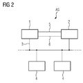
- FIG. 2 in which a known redundant automation system is shown.
- This has a first and a second subsystem 1, 2, which are connected via a field bus 3 with peripheral units 4.
- the fieldbus 3 for example, the PROFIBUS-DP specification is sufficient.
- other bus systems eg. As Ethernet (ProfiNet system redundancy), Modbus or even parallel bus systems suitable.
- the peripheral units 4 receive signals from transducers or transducers via input lines, which are used to detect a process status, and output via output lines signals to actuators with which the process is influenced. The process and the transducers, transducers and actuators are not shown in the figure for clarity.
- the two subsystems 1, 2 process the same control program, one of the subsystems 1, 2, the master function (mastership) and the other subsystem 1, 2 assumes the reserve function, with only the subsystem 1, 2 reading and / or writing accesses the peripheral devices that perform the master role or act as masters. In the event that the functioning as a master subsystem 1, 2 fails, the other subsystem 1, 2 takes over the master function. In order to enable both subsystems 1, 2 to process their respective control programs or program paths of these control programs synchronously, they synchronize via two synchronization connections 5, 6, the redundancy and monitoring functions being implemented via these two synchronization connections 5, 6.
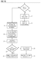
- FIG. 1 refers to, in which a flowchart for illustrating a troubleshooting operation is shown. It is assumed that the subsystem 1 (CPU 1) acts as a master and the subsystem 2 (CPU 2) as a backup and a loss of synchronization (branch 7) has been detected by means of suitable redundancy and monitoring functions of the master 1 and the reserve 2 the automation system AS changes from a redundant operation 26 into a solo operation.
- the subsystem 1 CPU 1
- CPU 2 the subsystem 2
- branch 7 a loss of synchronization
- a first operation 8 process inputs of a process image of the master 1 are first aligned with process inputs of a process image of the reserve 2 and set in a further operation 9, the communication of the reserve 2 with other not shown components of the automation system AS.
- the reserve 2 does not transmit any process output signals to the peripheral units 4.
- the reserve 2 starts the troubleshooting operation only after a predetermined time interval or time delay Ts (decision or branch 10).
- This time delay Ts which can be configured by means of an engineering system of the automation system AS, is chosen such that the reserve 2 can still reliably assume process control before a possible defect or failure of the master 1 (operation 11). In this case, the reserve 2 does not activate or start the troubleshooting operation at all.
- a defect or defect state is understood to mean a faulty operation of a faulty subsystem, within the scope of which this subsystem can not accomplish the process control.
- the reserve 2 starts the troubleshooting operation (step or operation 12).
- the reserve 2 detects that it is faulty (branch 13), which means that the reserve 2 is responsible for the loss of synchronization, the reserve 2 switches to a state "defective" (operation 14), wherein the Master continues the process control (Operation 15).
- the reserve 2 indicates this defect state to a service technician by means of suitable display means.
- the defect state thus indicates to the service technician which CPU (CPU module, CPU module) has to be replaced.
- the reserve 2 After updating the reserve 2, the reserve 2 assumes the mastership or process control as the "new" master (operation 20) and the master 1 acts as a "new" reserve, which starts another troubleshooting operation in an operation 21 so as to recognize it whether the "new" reserve - that is the "old” master 1 - is faulty.
- the "new" reserve (“old” master 1)
- the "new" reserve (old” master 1) with the relevant process control data of the "new” master (“old” reserve 2) and the automation system AS changes back from a single operation to redundant operation (operation 25).
- the "new" reserve changes to a defect state (operation 23) and the "new" master (“old” reserve 2) takes over the process control in a solo operation.
Landscapes
- Physics & Mathematics (AREA)
- General Physics & Mathematics (AREA)
- Engineering & Computer Science (AREA)
- Automation & Control Theory (AREA)
- Chemical & Material Sciences (AREA)
- Chemical Kinetics & Catalysis (AREA)
- Safety Devices In Control Systems (AREA)
- Hardware Redundancy (AREA)
Abstract
Description
- Die Erfindung betrifft ein Verfahren zum Betreiben eines redundanten, mit zwei Teilsystemen versehenen Automatisierungssystems, wobei in einem redundanten Betrieb eines der Teilsysteme als Master fungiert und die Prozesssteuerung übernimmt und das andere Teilsystem als Reserve fungiert.
- Ein derartiges Verfahren ist beispielsweise aus der
EP 0 907 912 B1 bekannt. Dort sind zwei Teilsysteme ereignissynchron gekoppelt, wobei an geeigneten Programmstellen, an denen ein Datenabgleich vorgesehen ist, beide Teilsysteme auf eine Antwort des jeweils anderen Teilnehmers warten und erst bei Erhalt der Antwort jeweils ihre Programmverarbeitung synchron fortsetzen. Allerdings kommt es häufig dann zu Synchronisationsproblemen, wenn in einem der beiden Teilsysteme transiente Fehler auftreten. Eine mögliche Ursache für derartige temporär auftretende und gewöhnlich nicht zu lokalisierende Fehler können "Bitkipper" im Arbeitsspeicher, "Bitkipper" im ASIC, Firmware-Fehler oder ein fehlerhaftes Verhalten eines Programms oder Programmteils sein, wobei dieses Verhalten sich nur unter einer bestimmten Bedingung einstellt. Ein transienter Fehler kann zu einem Totalausfall beider Teilsysteme führen, weil gewöhnlich das als Reserve fungierende Teilsystem zum Starten eines Fehlersuchbetriebs in einen STOPP-Zustand überführt wird und das noch laufende "fehlerbehaftete" und als Master fungierende Teilsystem kurz nach dieser Überführung ausfällt. Aufgrund eines derartigen Totalausfalls wird zunächst der zu steuernde Prozess heruntergefahren, das defekte Teilsystem ausgetauscht und schließlich der Prozess wieder angefahren, was eine hohe Stillstandszeit bedeutet. - Der Erfindung liegt daher die Aufgabe zugrunde, ein Verfahren zum Betreiben eines Automatisierungssystems gemäß dem Oberbegriff des Anspruchs 1 anzugeben, welches die Verfügbarkeit des Automatisierungssystems erhöht.
- Diese Aufgabe wird durch die im kennzeichnenden Teil des Anspruchs 1 angegebenen Maßnahmen gelöst.
- Vorteilhaft ist, dass unabhängig davon, ob transiente Fehler auf dem als Master oder auf dem als Reserve fungierenden Teilsystem auftreten, ein Totalausfall des Automatisierungssystems weitgehend vermieden wird.
- Die Erfindung geht von der Idee aus, nicht unmittelbar nach einem Synchronisationsverlust - sondern erst zeitverzögert - einen Fehlersuchbetrieb in dem als Reserve fungierenden Teilsystem zu starten, um die Ursache eines Synchronisationsverlusts bzw. den potentiellen Fehler auf der Reserve zu ermitteln. Dadurch wird weitgehend vermieden, dass für den Fall, dass der Master aufgrund eines transienten Fehlers ausfällt, die Reserve sich bereits im Fehlersuchbetrieb befindet und dadurch während des Fehlersuchbetriebs das Automatisierungssystem komplett ausfällt. Die Zeitverzögerung bzw. die Zeitspanne ist so gewählt, dass für den Fall, dass der Master während dieser Zeitspanne ausfällt, die Reserve die Prozesssteuerung übernehmen kann, wobei in diesem Fall, die Reserve den Fehlersuchbetrieb erst gar nicht aktiviert bzw. startet. Unter einem kompletten Ausfall des Automatisierungssystems wird verstanden, dass weder der Master noch die Reserve in der Lage ist, die Prozesssteuerung zu übernehmen.
- In einer Ausgestaltung der Erfindung gemäß den im Anspruch 2 angegebenen Maßnahmen ist vorgesehen, dass nach der vorgegebenen Zeitspanne (Timeout) und für den Fall, dass während des Fehlersuchbetriebs die Reserve einen Fehler detektiert, die Reserve einen Defekt-Zustand einnimmt. Der Master steuert immer noch in einem Solobetrieb den Prozess und es wird ermöglicht, dass ein Service-Techniker die Reserve austauschen kann. Unter einem Defekt-Zustand der Reserve wird ein gestörter Betrieb der Reserve verstanden, im Rahmen dessen die Reserve die Prozesssteuerung nicht bewerkstelligen kann.
- In einer weiteren Ausgestaltung der Erfindung gemäß den im Anspruch 3 angegebenen Maßnahmen ist vorgesehen, dass für den Fall, dass während des Fehlersuchbetriebs der Master ausfällt bzw. gestört ist und daher der Master die Masterschaft bzw. die Prozesssteuerung nicht verwirklichen bzw. fortführen kann, der Master zunächst interne Master-Daten der Reserve übermittelt und einen Defekt-Zustand anzeigt, wobei die Reserve als neuer Master die Prozesssteuerung übernimmt. Diese Umschaltung bzw. dieser Masterschafts-Wechsel erfolgt zwar nicht "stoßfrei" (sondern es erfolgt aufgrund der Umschaltung ein Sprung bzw. Stoß der Werte an den Prozessausgängen), es wird allerdings auch in diesem Fall vermieden, dass das Automatisierungssystem ausfällt.
- In einer Ausführungsform der Erfindung gemäß den im Anspruch 4 angegebenen Maßnahmen versorgt nach dem Fehlersuchbetrieb der Reserve der Master diese Reserve im Rahmen eines Aufdatens mit relevanten (Steuerungs-)Daten, wobei nach dem Aufdaten die Reserve als neuer Master die Prozesssteuerung übernimmt und der Master als neue Reserve einen weiteren Fehlersuchbetrieb startet. Dadurch wird geprüft, ob der "alte" Master ("neue" Reserve) für die Ursache des Synchronisationsverlustes bzw. für den Fehler verantwortlich ist, wobei der "neue" Master ("alte" Reserve) die Prozesssteuerung in einem Solobetrieb mit relevanten Steuerungs- bzw. Prozessdaten übernimmt.
- Weitere vorteilhafte Ausgestaltungen der Erfindung ergeben sich aus den weiteren Unteransprüchen.
- Anhand der Zeichnung, in der ein Ausführungsbeispiel der Erfindung veranschaulicht ist, werden im Folgenden die Erfindung, deren Ausgestaltungen sowie Vorteile näher erläutert.
- Es zeigen:
- Figur 1
- ein Flussdiagramm und
- Figur 2
- ein redundantes Automatisierungssystem.
- Die in den
Figuren 1 und2 gleichen Teile sind mit gleichen Bezugszeichen versehen. - Es wird zunächst auf
Figur 2 verwiesen, in welchem ein an sich bekanntes redundantes Automatisierungssystem dargestellt ist. Dieses weist ein erstes und ein zweites Teilsystem 1, 2 auf, die über einen Feldbus 3 mit Peripherieeinheiten 4 verbunden sind. Dabei genügt der Feldbus 3 beispielsweise der PROFIBUS-DP-Spezifikation. Prinzipiell sind auch andere Bussysteme, z. B. Ethernet (ProfiNet Systemredundanz), Modbus oder aber auch parallele Bussysteme geeignet. Die Peripherieeinheiten 4 erhalten über Eingangsleitungen Signale von Messumformern oder Messwertgebern, die zur Erfassung eines Prozesszustands dienen, und geben über Ausgangsleitungen Signale an Stellglieder aus, mit welchen der Prozess beeinflusst wird. Der Prozess sowie die Messumformer, Messwertgeber und Stellglieder sind in der Figur der Übersichtlichkeit wegen nicht dargestellt. Die beiden Teilsysteme 1, 2 verarbeiten das gleiche Steuerprogramm, wobei eines der Teilsysteme 1, 2 die Master-Funktion (Masterschaft) und das andere Teilsystem 1, 2 die Reserve-Funktion übernimmt, wobei nur das Teilsystem 1, 2 lesend und/oder schreibend auf die Peripherieeinheiten zugreift, das die Master-Funktion ausübt bzw. als Master fungiert. Für den Fall, dass das als Master fungierende Teilsystem 1, 2 ausfällt, übernimmt das andere Teilsystem 1, 2 die Master-Funktion. Um zu ermöglichen, dass beide Teilsysteme 1, 2 ihre jeweiligen Steuerprogramme bzw. Programmpfade dieser Steuerprogramme synchron verarbeiten, synchronisieren diese sich über zwei Synchronisationsverbindungen 5, 6 wobei die Redundanz- und Überwachungsfunktionen über diese beiden Synchronisationsverbindungen 5, 6 verwirklicht werden. - Es kann nun vorkommen, dass während des redundanten Betriebs des Automatisierungssystems AS beispielsweise aufgrund eines nicht rechtzeitig erkannten Speicherfehlers ein Synchronisationsverlust erkannt wird und daher das Automatisierungssystem AS von dem Redundanzbetrieb in einen Solobetrieb überführt wird, wobei ferner im Rahmen eines Fehlersuchbetriebs das Teilsystem 1, 2 lokalisiert wird, auf welchem der Fehler liegt bzw. welches für den Synchronisationsverlust verantwortlich ist.
- Im Folgenden wird auf
Figur 1 verwiesen, in welchem ein Flussdiagramm zur Veranschaulichung eines Fehlersuchbetriebs dargestellt wird. Es wird davon ausgegangen, dass das Teilsystem 1 (CPU 1) als Master und das Teilsystem 2 (CPU 2) als Reserve fungiert und ein Synchronisationsverlust (Verzweigung 7) mittels geeigneten Redundanz- und Überwachungsfunktionen des Masters 1 und der Reserve 2 erkannt wurde, wodurch das Automatisierungssystem AS von einem redundanten Betrieb 26 in einen Solobetrieb wechselt. - Im Rahmen einer ersten Operation 8 werden zunächst Prozesseingänge eines Prozessabbildes des Masters 1 mit Prozesseingängen eines Prozessabbildes der Reserve 2 abgeglichen und in einer weiteren Operation 9 die Kommunikation der Reserve 2 mit weiteren hier nicht dargestellten Komponenten des Automatisierungssystems AS eingestellt. Im Rahmen der Operation 9 übermittelt ferner die Reserve 2 den Peripherieeinheiten 4 keine Prozessausgangssignale. Um zu verhindern, dass während eines Fehlersuchbetriebs der Reserve 2 das Automatisierungssystem AS komplett ausfällt, weil der Master 1 fehlerbehaftet ist, startet die Reserve 2 den Fehlersuchbetrieb erst nach einer vorgegebenen Zeitspanne bzw. Zeitverzögerung Ts (Entscheidung bzw. Verzweigung 10). Diese Zeitverzögerung Ts, welche mittels eines Engineering-Systems des Automatisierungssystems AS projektierbar ist, ist so gewählt, dass die Reserve 2 vor einem möglichen Defekt bzw. Ausfall des Masters 1 die Prozesssteuerung noch sicher übernehmen kann (Operation 11). In diesem Fall aktiviert bzw. startet die Reserve 2 den Fehlersuchbetrieb erst gar nicht. Es wird darauf hingewiesen, dass unter einem Defekt bzw. Defekt-Zustand ein gestörter Betrieb eines fehlerbehafteten Teilsystems verstanden wird, im Rahmen dessen dieses Teilsystem die Prozesssteuerung nicht bewerkstelligen kann.
- Für den Fall, dass der Master 1 während dieser vorgegebenen Zeitspanne Ts nicht ausgefallen ist, startet die Reserve 2 den Fehlersuchbetrieb (Schritt bzw. Operation 12). Für den Fall, dass die Reserve 2 erkennt, dass sie fehlerbehaftet ist (Verzweigung 13), was bedeutet, dass die Reserve 2 für den Synchronisationsverlust verantwortlich ist, schaltet sich die Reserve 2 in einen Zustand "defekt" (Operation 14), wobei der Master die Prozesssteuerung fortsetzt (Operation 15). Die Reserve 2 zeigt mittels geeigneter Anzeigemittel einem Service-Techniker diesen Defektzustand an. Der Defektzustand zeigt dem Service-Techniker somit an, welche CPU (CPU-Baugruppe, CPU-Modul) ersetzt werden muss.
- Es kann vorkommen, dass während des Fehlersuchbetriebs der Reserve 2 der Master 1 im Hinblick auf die Prozesssteuerung ausfällt (Verzweigung 16). In diesem Fall übernimmt die Reserve 2 in einem Schritt 17 die internen Master-Daten (Werte eine Timers, Werte eines Zählers, Inhalte von Datenbausteinen, ...) und übernimmt anschließend die Prozesssteuerung, wobei der Wechsel nicht "stoßfrei" erfolgt (Operation 18). Ein Service-Techniker kann den gestörten Master 1 durch eine neue CPU (CPU-Baugruppe, CPU-Modul) ersetzen.
- Für den Fall dagegen, dass während des Fehlersuchbetriebs der Reserve 2 der Master 1 nicht gestört ist (Verzweigung 16) wird nach dem Fehlersuchbetrieb in einer Operation 19 die Reserve 2 durch den Master 1 "aufgedated", wodurch die Reserve 2 alle relevanten Prozesssteuerdaten des Masters 1 übernimmt. Dadurch wird ermöglicht, zu einem späteren Zeitpunkt, zu dem sowohl der Master 1 als auch die Reserve 2 jeweils den Fehlersuchbetrieb beendet haben, das Automatisierungssystem AS von dem Solobetrieb in den Redundanzbetrieb zu überführen. Nach dem Aufdaten der Reserve 2 übernimmt die Reserve 2 als "neuer" Master die Masterschaft bzw. die Prozesssteuerung (Operation 20) und der Master 1 fungiert als "neue" Reserve, die in einer Operation 21 einen weiteren Fehlersuchbetrieb startet, um somit zu erkennen, ob die "neue" Reserve - also der "alte" Master 1 - fehlerbehaftet ist. Für den Fall, dass die "neue" Reserve ("alter" Master 1) keinen Fehler detektiert hat, wird die "neue" Reserve ("alter" Master 1) mit den relevanten Prozesssteuerdaten des "neuen" Masters ("alte" Reserve 2) "aufgedated" und das Automatisierungssystem AS wechselt wieder von einem Solobetrieb in den redundanten Betrieb (Operation 25). Für den Fall dagegen, dass die "neue" Reserve einen Fehler detektiert hat, wechselt die "neue" Reserve in einen Defektzustand (Operation 23) und der "neue" Master ("alte" Reserve 2) übernimmt in einem Solobetrieb die Prozesssteuerung.
Claims (7)
- Verfahren zum Betreiben eines redundanten mit zwei Teilsystemen (1, 2) versehenen Automatisierungssystems (AS), wobei in einem redundanten Betrieb eines der Teilsysteme (1) als Master fungiert und die Prozesssteuerung übernimmt und das andere Teilsystem (2) als Reserve fungiert, dadurch gekennzeichnet, dass der Master (1) und die Reserve (2) sich über Kommunikationsmittel synchronisieren und im Falle eines Synchronisationsverlustesa. Prozesseingänge eines Prozessabbildes des Masters (1) mit Prozesseingängen eines Prozessabbildes der Reserve (2) abgeglichen werden,b. die Kommunikation der Reserve (2) mit weiteren Komponenten des Automatisierungssystems (AS) eingestellt wird,c. für den Fall, dass der Master (1) während einer vorgegebenen Zeitspanne (Ts) nicht ausfällt, die Reserve (2) nach dieser Zeitspanne (Ts) zur Ermittlung der Ursache des Synchronisationsverlustes einen Fehlersuchbetrieb startet,d. für den Fall, dass der Master (1) während der vorgegebenen Zeitspanne (Ts) ausfällt, die Reserve (2) als neuer Master die Prozesssteuerung übernimmt.
- Verfahren nach Anspruch 1, dadurch gekennzeichnet, dass für den Fall, dass während des Fehlersuchbetriebs die Reserve (2) einen Fehler detektiert, die Reserve (2) einen Defekt-Zustand einnimmt.
- Verfahren nach Anspruch 1, dadurch gekennzeichnet, dass für den Fall, dass während des Fehlersuchbetriebs der Master (1) gestört ist, der Master (1) interne Master-Daten der Reserve (2) übermittelt und einen Defekt-Zustand anzeigt, wobei die Reserve (2) als neuer Master die Prozesssteuerung übernimmt.
- Verfahren nach Anspruch 1, dadurch gekennzeichnet, dass der Master (1) nach dem Fehlersuchbetrieb die Reserve (2) im Rahmen eines Aufdatens mit relevanten Prozesssteuer-Daten versorgt, wobei nach dem Aufdaten die Reserve (2) als neuer Master die Prozesssteuerung übernimmt und der Master (1) als neue Reserve die in den Ansprüchen 2 bis 4 angegebenen Maßnahmen wiederholt.
- Verfahren nach einem der Ansprüche 1 bis 4, dadurch gekennzeichnet, dass die vorgegebene Zeitspanne (Ts) mittels eines Engineering-Systems projektierbar ist.
- Redundantes mit zwei Teilsystemen (1, 2) versehenes Automatisierungssystem (AS), wobei in einem redundanten Betrieb eines der Teilsysteme (1) als Master fungiert und die Prozesssteuerung übernimmt und das andere Teilsystem (2) als Reserve fungiert, dadurch gekennzeichnet, dass der Master (1) und die Reserve (2) zur Ausführung des Verfahrens nach einem der Ansprüche 1 bis 4 bestimmt und eingerichtet sind.
- Redundantes Automatisierungssystem (AS) nach Anspruch 6, dadurch gekennzeichnet, dass die vorgegebene Zeitspanne (Ts) mittels eines Engineering-Systems des Automatisierungssystems (AS) projektierbar ist.
Priority Applications (3)
| Application Number | Priority Date | Filing Date | Title |
|---|---|---|---|
| EP16169894.9A EP3246771B1 (de) | 2016-05-17 | 2016-05-17 | Verfahren zum betreiben eines redundanten automatisierungssystems |
| US15/596,269 US11262745B2 (en) | 2016-05-17 | 2017-05-16 | Method for operating a redundant automation system to increase availability of the automation system |
| CN201710345783.0A CN107390511B (zh) | 2016-05-17 | 2017-05-16 | 用于运行冗余的自动化系统的方法 |
Applications Claiming Priority (1)
| Application Number | Priority Date | Filing Date | Title |
|---|---|---|---|
| EP16169894.9A EP3246771B1 (de) | 2016-05-17 | 2016-05-17 | Verfahren zum betreiben eines redundanten automatisierungssystems |
Publications (2)
| Publication Number | Publication Date |
|---|---|
| EP3246771A1 true EP3246771A1 (de) | 2017-11-22 |
| EP3246771B1 EP3246771B1 (de) | 2021-06-30 |
Family
ID=56014859
Family Applications (1)
| Application Number | Title | Priority Date | Filing Date |
|---|---|---|---|
| EP16169894.9A Active EP3246771B1 (de) | 2016-05-17 | 2016-05-17 | Verfahren zum betreiben eines redundanten automatisierungssystems |
Country Status (3)
| Country | Link |
|---|---|
| US (1) | US11262745B2 (de) |
| EP (1) | EP3246771B1 (de) |
| CN (1) | CN107390511B (de) |
Families Citing this family (24)
| Publication number | Priority date | Publication date | Assignee | Title |
|---|---|---|---|---|
| WO2021144656A1 (en) | 2020-01-15 | 2021-07-22 | Monday.Com | Digital processing systems and methods for graphical dynamic table gauges in collaborative work systems |
| WO2021161104A1 (en) | 2020-02-12 | 2021-08-19 | Monday.Com | Enhanced display features in collaborative network systems, methods, and devices |
| US11410129B2 (en) | 2010-05-01 | 2022-08-09 | Monday.com Ltd. | Digital processing systems and methods for two-way syncing with third party applications in collaborative work systems |
| EP3547618B1 (de) * | 2018-03-29 | 2023-03-01 | Siemens Aktiengesellschaft | Verfahren zum aufbau einer redundanten kommunikationsverbindung und ausfallgesicherte steuerungseinheit |
| US11436359B2 (en) | 2018-07-04 | 2022-09-06 | Monday.com Ltd. | System and method for managing permissions of users for a single data type column-oriented data structure |
| US11698890B2 (en) | 2018-07-04 | 2023-07-11 | Monday.com Ltd. | System and method for generating a column-oriented data structure repository for columns of single data types |
| US12353419B2 (en) | 2018-07-23 | 2025-07-08 | Monday.com Ltd. | System and method for generating a tagged column-oriented data structure |
| CN111142368B (zh) * | 2019-09-02 | 2023-08-04 | 浙江中控技术股份有限公司 | 一种批量控制器失效保护方法 |
| US11507738B2 (en) | 2019-11-18 | 2022-11-22 | Monday.Com | Digital processing systems and methods for automatic updates in collaborative work systems |
| EP4062313A1 (de) | 2019-11-18 | 2022-09-28 | Monday.com Ltd. | Kollaborative netzwerksysteme, verfahren und vorrichtungen |
| EP4143732A1 (de) | 2020-05-01 | 2023-03-08 | Monday.com Ltd. | Digitale verarbeitungssysteme und verfahren für verbesserten kollaborativen arbeitsablauf sowie vernetzungssysteme, verfahren und vorrichtungen |
| US11829953B1 (en) | 2020-05-01 | 2023-11-28 | Monday.com Ltd. | Digital processing systems and methods for managing sprints using linked electronic boards |
| US11277361B2 (en) | 2020-05-03 | 2022-03-15 | Monday.com Ltd. | Digital processing systems and methods for variable hang-time for social layer messages in collaborative work systems |
| EP3936949A1 (de) * | 2020-07-09 | 2022-01-12 | Siemens Aktiengesellschaft | Verfahren zum betreiben eines redundanten automatisierungssystems und redundantes automatisierungssystem |
| US11782582B2 (en) | 2021-01-14 | 2023-10-10 | Monday.com Ltd. | Digital processing systems and methods for detectable codes in presentation enabling targeted feedback in collaborative work systems |
| US12056664B2 (en) | 2021-08-17 | 2024-08-06 | Monday.com Ltd. | Digital processing systems and methods for external events trigger automatic text-based document alterations in collaborative work systems |
| US12105948B2 (en) | 2021-10-29 | 2024-10-01 | Monday.com Ltd. | Digital processing systems and methods for display navigation mini maps |
| US20250123600A1 (en) * | 2022-03-18 | 2025-04-17 | Telefonaktiebolaget Lm Ericsson (Publ) | Methods, Computing Nodes and System for Controlling a Physical Entity |
| US11741071B1 (en) | 2022-12-28 | 2023-08-29 | Monday.com Ltd. | Digital processing systems and methods for navigating and viewing displayed content |
| US11886683B1 (en) | 2022-12-30 | 2024-01-30 | Monday.com Ltd | Digital processing systems and methods for presenting board graphics |
| US11893381B1 (en) | 2023-02-21 | 2024-02-06 | Monday.com Ltd | Digital processing systems and methods for reducing file bundle sizes |
| WO2024257014A1 (en) | 2023-06-13 | 2024-12-19 | Monday.com Ltd. | Digital processing systems and methods for enhanced data representation |
| WO2025114749A1 (en) | 2023-11-28 | 2025-06-05 | Monday.com Ltd. | Digital processing systems and methods for facilitating the development and implementation of applications in conjunction with a serverless environment |
| WO2025114750A1 (en) | 2023-11-28 | 2025-06-05 | Monday.com Ltd. | Digital processing systems and methods for managing workflows |
Citations (3)
| Publication number | Priority date | Publication date | Assignee | Title |
|---|---|---|---|---|
| EP0907912B1 (de) | 1996-06-24 | 2000-05-03 | Siemens Aktiengesellschaft | Synchronisationsverfahren |
| EP2765464A1 (de) * | 2013-02-08 | 2014-08-13 | Siemens Aktiengesellschaft | Verfahren zum Betreiben eines redundanten Automatisierungssystems |
| US20150095690A1 (en) * | 2013-10-01 | 2015-04-02 | Siemens Aktiengesellschaft | Redundant Automation System |
Family Cites Families (7)
| Publication number | Priority date | Publication date | Assignee | Title |
|---|---|---|---|---|
| US5099153A (en) * | 1990-08-13 | 1992-03-24 | Dallas Semiconductor Corporation | Frequency-independent monitor circuit |
| US5777874A (en) * | 1996-02-12 | 1998-07-07 | Allen-Bradley Company, Inc. | Programmable controller backup system |
| US7707619B2 (en) * | 2005-01-28 | 2010-04-27 | Microsoft Corporation | Method and system for troubleshooting when a program is adversely impacted by a security policy |
| US7617412B2 (en) * | 2006-10-25 | 2009-11-10 | Rockwell Automation Technologies, Inc. | Safety timer crosscheck diagnostic in a dual-CPU safety system |
| CN100492223C (zh) * | 2007-03-30 | 2009-05-27 | 哈尔滨工程大学 | 发动机冗余电控系统切换电路 |
| CN103107904A (zh) * | 2011-11-15 | 2013-05-15 | 北京南车时代信息技术有限公司 | 一种ats系统控制中心应用服务器的双机切换方法 |
| CN103955188B (zh) | 2014-04-24 | 2017-02-15 | 清华大学 | 支持冗余切换功能的控制系统及方法 |
-
2016
- 2016-05-17 EP EP16169894.9A patent/EP3246771B1/de active Active
-
2017
- 2017-05-16 US US15/596,269 patent/US11262745B2/en not_active Expired - Fee Related
- 2017-05-16 CN CN201710345783.0A patent/CN107390511B/zh active Active
Patent Citations (3)
| Publication number | Priority date | Publication date | Assignee | Title |
|---|---|---|---|---|
| EP0907912B1 (de) | 1996-06-24 | 2000-05-03 | Siemens Aktiengesellschaft | Synchronisationsverfahren |
| EP2765464A1 (de) * | 2013-02-08 | 2014-08-13 | Siemens Aktiengesellschaft | Verfahren zum Betreiben eines redundanten Automatisierungssystems |
| US20150095690A1 (en) * | 2013-10-01 | 2015-04-02 | Siemens Aktiengesellschaft | Redundant Automation System |
Also Published As
| Publication number | Publication date |
|---|---|
| EP3246771B1 (de) | 2021-06-30 |
| US11262745B2 (en) | 2022-03-01 |
| US20170351252A1 (en) | 2017-12-07 |
| CN107390511A (zh) | 2017-11-24 |
| CN107390511B (zh) | 2021-12-07 |
Similar Documents
| Publication | Publication Date | Title |
|---|---|---|
| EP3246771B1 (de) | Verfahren zum betreiben eines redundanten automatisierungssystems | |
| DE3225455C2 (de) | Verfahren zum sicheren Betrieb eines redundanten Steuersystems | |
| DE1524239B2 (de) | Schaltungsanordnung zur aufrechterhaltung eines fehler freien betriebes bei einer rechenanlage mit mindestens zwei parallel arbeitenden rechengeraeten | |
| DE102012003242A1 (de) | Verfahren zum ausfallsicheren Betreiben eines Prozesssteuersystems mit redundanten Steuereinrichtungen | |
| DE102016102259A1 (de) | Rechner- und Funktionsarchitektur zur Erhöhung der Ausfallsicherheit einer Hilfskraftlenkung | |
| DE2317576A1 (de) | Einrichtung zur ausfallbedingten umordnung von speichermoduln in einer datenverarbeitungsanlage | |
| DE69125778T2 (de) | Verfahren zur Sicherung von in einer Primär- und Sekundärdatenbank gespeicherten Daten in einem Prozessregelsystem | |
| EP3214512B1 (de) | Redundantes steuersystem für einen aktor und verfahren zu seiner redundanten steuerung | |
| DE2453011A1 (de) | Verfahren und schaltungsanordnung zur auswahl eines signals aus wenigstens drei redundanten signalkanaelen | |
| DE19842593C2 (de) | Verfahren zum Betrieb eines Busmasters an einem Feldbus | |
| EP3557356A1 (de) | Verfahren und automatisierungssystem zum sicheren automatischen betrieb einer maschine oder eines fahrzeugs | |
| WO2005106603A1 (de) | Redundantes automatisierungssystem umfassend ein master- und ein stand-by-automatisierungsgerät | |
| EP2418580B1 (de) | Verfahren zum Betreiben eines Netzwerkes und Netzwerk | |
| DE102010041437B4 (de) | Überprüfung von Funktionen eines Steuersystems mit Komponenten | |
| WO2014161986A1 (de) | Steuer- und datenübertragungsanlage zur redundanten prozesssteuerung und verfahren zur firmware-aktualisierung | |
| DE102018000063A1 (de) | Spannungsdiagnoseschaltung | |
| EP2048555A1 (de) | Analoge Ausgabeeinheit mit Fehlererkennung | |
| DE10329196A1 (de) | Verfahren zum Reset von elektronischen Fahrzeug-Steuergeräten | |
| DE102020200141A1 (de) | Fehlertolerantes Regelsystem | |
| EP2520989A2 (de) | Verfahren zum Betrieb eines hochverfügbaren Systems mit funktionaler Sicherheit sowie ein hochverfügbares System mit funktionaler Sicherheit | |
| DE2913371A1 (de) | Verfahren und system zur ablaufsteuerung | |
| DE102019117952B4 (de) | Verfahren zum Betreiben einer Verarbeitungsvorrichtung zur Steuerung und/oder Regelung eines Datenstroms | |
| EP3229141A1 (de) | Verfahren zur erhöhung der verfügbarkeit eines redundanten automatisierungssystems sowie redundantes automatisierungssystem | |
| EP3565752A1 (de) | Umschaltung zwischen element-controllern im bahnbetrieb | |
| WO2005057306A1 (de) | Peripherieeinheit für ein redundantes steuersystem |
Legal Events
| Date | Code | Title | Description |
|---|---|---|---|
| PUAI | Public reference made under article 153(3) epc to a published international application that has entered the european phase |
Free format text: ORIGINAL CODE: 0009012 |
|
| STAA | Information on the status of an ep patent application or granted ep patent |
Free format text: STATUS: THE APPLICATION HAS BEEN PUBLISHED |
|
| AK | Designated contracting states |
Kind code of ref document: A1 Designated state(s): AL AT BE BG CH CY CZ DE DK EE ES FI FR GB GR HR HU IE IS IT LI LT LU LV MC MK MT NL NO PL PT RO RS SE SI SK SM TR |
|
| AX | Request for extension of the european patent |
Extension state: BA ME |
|
| STAA | Information on the status of an ep patent application or granted ep patent |
Free format text: STATUS: REQUEST FOR EXAMINATION WAS MADE |
|
| 17P | Request for examination filed |
Effective date: 20180504 |
|
| RBV | Designated contracting states (corrected) |
Designated state(s): AL AT BE BG CH CY CZ DE DK EE ES FI FR GB GR HR HU IE IS IT LI LT LU LV MC MK MT NL NO PL PT RO RS SE SI SK SM TR |
|
| GRAP | Despatch of communication of intention to grant a patent |
Free format text: ORIGINAL CODE: EPIDOSNIGR1 |
|
| STAA | Information on the status of an ep patent application or granted ep patent |
Free format text: STATUS: GRANT OF PATENT IS INTENDED |
|
| RIC1 | Information provided on ipc code assigned before grant |
Ipc: G05B 19/042 20060101AFI20210223BHEP |
|
| GRAS | Grant fee paid |
Free format text: ORIGINAL CODE: EPIDOSNIGR3 |
|
| INTG | Intention to grant announced |
Effective date: 20210322 |
|
| GRAA | (expected) grant |
Free format text: ORIGINAL CODE: 0009210 |
|
| STAA | Information on the status of an ep patent application or granted ep patent |
Free format text: STATUS: THE PATENT HAS BEEN GRANTED |
|
| AK | Designated contracting states |
Kind code of ref document: B1 Designated state(s): AL AT BE BG CH CY CZ DE DK EE ES FI FR GB GR HR HU IE IS IT LI LT LU LV MC MK MT NL NO PL PT RO RS SE SI SK SM TR |
|
| REG | Reference to a national code |
Ref country code: CH Ref legal event code: EP |
|
| REG | Reference to a national code |
Ref country code: AT Ref legal event code: REF Ref document number: 1406915 Country of ref document: AT Kind code of ref document: T Effective date: 20210715 |
|
| REG | Reference to a national code |
Ref country code: DE Ref legal event code: R096 Ref document number: 502016013296 Country of ref document: DE |
|
| REG | Reference to a national code |
Ref country code: IE Ref legal event code: FG4D Free format text: LANGUAGE OF EP DOCUMENT: GERMAN |
|
| REG | Reference to a national code |
Ref country code: LT Ref legal event code: MG9D |
|
| PG25 | Lapsed in a contracting state [announced via postgrant information from national office to epo] |
Ref country code: HR Free format text: LAPSE BECAUSE OF FAILURE TO SUBMIT A TRANSLATION OF THE DESCRIPTION OR TO PAY THE FEE WITHIN THE PRESCRIBED TIME-LIMIT Effective date: 20210630 Ref country code: BG Free format text: LAPSE BECAUSE OF FAILURE TO SUBMIT A TRANSLATION OF THE DESCRIPTION OR TO PAY THE FEE WITHIN THE PRESCRIBED TIME-LIMIT Effective date: 20210930 Ref country code: FI Free format text: LAPSE BECAUSE OF FAILURE TO SUBMIT A TRANSLATION OF THE DESCRIPTION OR TO PAY THE FEE WITHIN THE PRESCRIBED TIME-LIMIT Effective date: 20210630 |
|
| REG | Reference to a national code |
Ref country code: NL Ref legal event code: MP Effective date: 20210630 |
|
| PG25 | Lapsed in a contracting state [announced via postgrant information from national office to epo] |
Ref country code: LV Free format text: LAPSE BECAUSE OF FAILURE TO SUBMIT A TRANSLATION OF THE DESCRIPTION OR TO PAY THE FEE WITHIN THE PRESCRIBED TIME-LIMIT Effective date: 20210630 Ref country code: GR Free format text: LAPSE BECAUSE OF FAILURE TO SUBMIT A TRANSLATION OF THE DESCRIPTION OR TO PAY THE FEE WITHIN THE PRESCRIBED TIME-LIMIT Effective date: 20211001 Ref country code: NO Free format text: LAPSE BECAUSE OF FAILURE TO SUBMIT A TRANSLATION OF THE DESCRIPTION OR TO PAY THE FEE WITHIN THE PRESCRIBED TIME-LIMIT Effective date: 20210930 Ref country code: RS Free format text: LAPSE BECAUSE OF FAILURE TO SUBMIT A TRANSLATION OF THE DESCRIPTION OR TO PAY THE FEE WITHIN THE PRESCRIBED TIME-LIMIT Effective date: 20210630 Ref country code: SE Free format text: LAPSE BECAUSE OF FAILURE TO SUBMIT A TRANSLATION OF THE DESCRIPTION OR TO PAY THE FEE WITHIN THE PRESCRIBED TIME-LIMIT Effective date: 20210630 |
|
| PG25 | Lapsed in a contracting state [announced via postgrant information from national office to epo] |
Ref country code: SM Free format text: LAPSE BECAUSE OF FAILURE TO SUBMIT A TRANSLATION OF THE DESCRIPTION OR TO PAY THE FEE WITHIN THE PRESCRIBED TIME-LIMIT Effective date: 20210630 Ref country code: SK Free format text: LAPSE BECAUSE OF FAILURE TO SUBMIT A TRANSLATION OF THE DESCRIPTION OR TO PAY THE FEE WITHIN THE PRESCRIBED TIME-LIMIT Effective date: 20210630 Ref country code: EE Free format text: LAPSE BECAUSE OF FAILURE TO SUBMIT A TRANSLATION OF THE DESCRIPTION OR TO PAY THE FEE WITHIN THE PRESCRIBED TIME-LIMIT Effective date: 20210630 Ref country code: CZ Free format text: LAPSE BECAUSE OF FAILURE TO SUBMIT A TRANSLATION OF THE DESCRIPTION OR TO PAY THE FEE WITHIN THE PRESCRIBED TIME-LIMIT Effective date: 20210630 Ref country code: RO Free format text: LAPSE BECAUSE OF FAILURE TO SUBMIT A TRANSLATION OF THE DESCRIPTION OR TO PAY THE FEE WITHIN THE PRESCRIBED TIME-LIMIT Effective date: 20210630 Ref country code: NL Free format text: LAPSE BECAUSE OF FAILURE TO SUBMIT A TRANSLATION OF THE DESCRIPTION OR TO PAY THE FEE WITHIN THE PRESCRIBED TIME-LIMIT Effective date: 20210630 Ref country code: PT Free format text: LAPSE BECAUSE OF FAILURE TO SUBMIT A TRANSLATION OF THE DESCRIPTION OR TO PAY THE FEE WITHIN THE PRESCRIBED TIME-LIMIT Effective date: 20211102 Ref country code: ES Free format text: LAPSE BECAUSE OF FAILURE TO SUBMIT A TRANSLATION OF THE DESCRIPTION OR TO PAY THE FEE WITHIN THE PRESCRIBED TIME-LIMIT Effective date: 20210630 |
|
| PG25 | Lapsed in a contracting state [announced via postgrant information from national office to epo] |
Ref country code: PL Free format text: LAPSE BECAUSE OF FAILURE TO SUBMIT A TRANSLATION OF THE DESCRIPTION OR TO PAY THE FEE WITHIN THE PRESCRIBED TIME-LIMIT Effective date: 20210630 |
|
| REG | Reference to a national code |
Ref country code: DE Ref legal event code: R097 Ref document number: 502016013296 Country of ref document: DE |
|
| PG25 | Lapsed in a contracting state [announced via postgrant information from national office to epo] |
Ref country code: DK Free format text: LAPSE BECAUSE OF FAILURE TO SUBMIT A TRANSLATION OF THE DESCRIPTION OR TO PAY THE FEE WITHIN THE PRESCRIBED TIME-LIMIT Effective date: 20210630 |
|
| PLBE | No opposition filed within time limit |
Free format text: ORIGINAL CODE: 0009261 |
|
| STAA | Information on the status of an ep patent application or granted ep patent |
Free format text: STATUS: NO OPPOSITION FILED WITHIN TIME LIMIT |
|
| PG25 | Lapsed in a contracting state [announced via postgrant information from national office to epo] |
Ref country code: AL Free format text: LAPSE BECAUSE OF FAILURE TO SUBMIT A TRANSLATION OF THE DESCRIPTION OR TO PAY THE FEE WITHIN THE PRESCRIBED TIME-LIMIT Effective date: 20210630 |
|
| 26N | No opposition filed |
Effective date: 20220331 |
|
| REG | Reference to a national code |
Ref country code: CH Ref legal event code: PL |
|
| REG | Reference to a national code |
Ref country code: BE Ref legal event code: MM Effective date: 20220531 |
|
| PG25 | Lapsed in a contracting state [announced via postgrant information from national office to epo] |
Ref country code: MC Free format text: LAPSE BECAUSE OF FAILURE TO SUBMIT A TRANSLATION OF THE DESCRIPTION OR TO PAY THE FEE WITHIN THE PRESCRIBED TIME-LIMIT Effective date: 20210630 Ref country code: LU Free format text: LAPSE BECAUSE OF NON-PAYMENT OF DUE FEES Effective date: 20220517 Ref country code: LI Free format text: LAPSE BECAUSE OF NON-PAYMENT OF DUE FEES Effective date: 20220531 Ref country code: CH Free format text: LAPSE BECAUSE OF NON-PAYMENT OF DUE FEES Effective date: 20220531 |
|
| PG25 | Lapsed in a contracting state [announced via postgrant information from national office to epo] |
Ref country code: LT Free format text: LAPSE BECAUSE OF FAILURE TO SUBMIT A TRANSLATION OF THE DESCRIPTION OR TO PAY THE FEE WITHIN THE PRESCRIBED TIME-LIMIT Effective date: 20210630 Ref country code: IE Free format text: LAPSE BECAUSE OF NON-PAYMENT OF DUE FEES Effective date: 20220517 |
|
| PG25 | Lapsed in a contracting state [announced via postgrant information from national office to epo] |
Ref country code: BE Free format text: LAPSE BECAUSE OF NON-PAYMENT OF DUE FEES Effective date: 20220531 |
|
| REG | Reference to a national code |
Ref country code: AT Ref legal event code: MM01 Ref document number: 1406915 Country of ref document: AT Kind code of ref document: T Effective date: 20220517 |
|
| PG25 | Lapsed in a contracting state [announced via postgrant information from national office to epo] |
Ref country code: AT Free format text: LAPSE BECAUSE OF NON-PAYMENT OF DUE FEES Effective date: 20220517 |
|
| PG25 | Lapsed in a contracting state [announced via postgrant information from national office to epo] |
Ref country code: HU Free format text: LAPSE BECAUSE OF FAILURE TO SUBMIT A TRANSLATION OF THE DESCRIPTION OR TO PAY THE FEE WITHIN THE PRESCRIBED TIME-LIMIT; INVALID AB INITIO Effective date: 20160517 |
|
| PG25 | Lapsed in a contracting state [announced via postgrant information from national office to epo] |
Ref country code: MK Free format text: LAPSE BECAUSE OF FAILURE TO SUBMIT A TRANSLATION OF THE DESCRIPTION OR TO PAY THE FEE WITHIN THE PRESCRIBED TIME-LIMIT Effective date: 20210630 Ref country code: CY Free format text: LAPSE BECAUSE OF FAILURE TO SUBMIT A TRANSLATION OF THE DESCRIPTION OR TO PAY THE FEE WITHIN THE PRESCRIBED TIME-LIMIT Effective date: 20210630 |
|
| PG25 | Lapsed in a contracting state [announced via postgrant information from national office to epo] |
Ref country code: TR Free format text: LAPSE BECAUSE OF FAILURE TO SUBMIT A TRANSLATION OF THE DESCRIPTION OR TO PAY THE FEE WITHIN THE PRESCRIBED TIME-LIMIT Effective date: 20210630 |
|
| PGFP | Annual fee paid to national office [announced via postgrant information from national office to epo] |
Ref country code: GB Payment date: 20240603 Year of fee payment: 9 |
|
| PGFP | Annual fee paid to national office [announced via postgrant information from national office to epo] |
Ref country code: FR Payment date: 20240515 Year of fee payment: 9 |
|
| PG25 | Lapsed in a contracting state [announced via postgrant information from national office to epo] |
Ref country code: MT Free format text: LAPSE BECAUSE OF FAILURE TO SUBMIT A TRANSLATION OF THE DESCRIPTION OR TO PAY THE FEE WITHIN THE PRESCRIBED TIME-LIMIT Effective date: 20210630 |
|
| PGFP | Annual fee paid to national office [announced via postgrant information from national office to epo] |
Ref country code: IT Payment date: 20240522 Year of fee payment: 9 |
|
| PGFP | Annual fee paid to national office [announced via postgrant information from national office to epo] |
Ref country code: DE Payment date: 20240719 Year of fee payment: 9 |
|
| REG | Reference to a national code |
Ref country code: DE Ref legal event code: R119 Ref document number: 502016013296 Country of ref document: DE |
|
| GBPC | Gb: european patent ceased through non-payment of renewal fee |
Effective date: 20250517 |
|
| PG25 | Lapsed in a contracting state [announced via postgrant information from national office to epo] |
Ref country code: GB Free format text: LAPSE BECAUSE OF NON-PAYMENT OF DUE FEES Effective date: 20250517 |
|
| PG25 | Lapsed in a contracting state [announced via postgrant information from national office to epo] |
Ref country code: DE Free format text: LAPSE BECAUSE OF NON-PAYMENT OF DUE FEES Effective date: 20251202 |
|
| PG25 | Lapsed in a contracting state [announced via postgrant information from national office to epo] |
Ref country code: IT Free format text: LAPSE BECAUSE OF NON-PAYMENT OF DUE FEES Effective date: 20250517 |
|
| PG25 | Lapsed in a contracting state [announced via postgrant information from national office to epo] |
Ref country code: FR Free format text: LAPSE BECAUSE OF NON-PAYMENT OF DUE FEES Effective date: 20250531 |