EP3246996B1 - Appareil pour un système de rail de barre omnibus - Google Patents
Appareil pour un système de rail de barre omnibus Download PDFInfo
- Publication number
- EP3246996B1 EP3246996B1 EP17153517.2A EP17153517A EP3246996B1 EP 3246996 B1 EP3246996 B1 EP 3246996B1 EP 17153517 A EP17153517 A EP 17153517A EP 3246996 B1 EP3246996 B1 EP 3246996B1
- Authority
- EP
- European Patent Office
- Prior art keywords
- contact
- busbar
- openings
- base plate
- plate module
- Prior art date
- Legal status (The legal status is an assumption and is not a legal conclusion. Google has not performed a legal analysis and makes no representation as to the accuracy of the status listed.)
- Active
Links
Images


Classifications
-
- H—ELECTRICITY
- H01—ELECTRIC ELEMENTS
- H01R—ELECTRICALLY-CONDUCTIVE CONNECTIONS; STRUCTURAL ASSOCIATIONS OF A PLURALITY OF MUTUALLY-INSULATED ELECTRICAL CONNECTING ELEMENTS; COUPLING DEVICES; CURRENT COLLECTORS
- H01R13/00—Details of coupling devices of the kinds covered by groups H01R12/70 or H01R24/00 - H01R33/00
- H01R13/44—Means for preventing access to live contacts
- H01R13/447—Shutter or cover plate
-
- H—ELECTRICITY
- H01—ELECTRIC ELEMENTS
- H01R—ELECTRICALLY-CONDUCTIVE CONNECTIONS; STRUCTURAL ASSOCIATIONS OF A PLURALITY OF MUTUALLY-INSULATED ELECTRICAL CONNECTING ELEMENTS; COUPLING DEVICES; CURRENT COLLECTORS
- H01R13/00—Details of coupling devices of the kinds covered by groups H01R12/70 or H01R24/00 - H01R33/00
- H01R13/40—Securing contact members in or to a base or case; Insulating of contact members
-
- H—ELECTRICITY
- H01—ELECTRIC ELEMENTS
- H01R—ELECTRICALLY-CONDUCTIVE CONNECTIONS; STRUCTURAL ASSOCIATIONS OF A PLURALITY OF MUTUALLY-INSULATED ELECTRICAL CONNECTING ELEMENTS; COUPLING DEVICES; CURRENT COLLECTORS
- H01R13/00—Details of coupling devices of the kinds covered by groups H01R12/70 or H01R24/00 - H01R33/00
- H01R13/46—Bases; Cases
- H01R13/502—Bases; Cases composed of different pieces
- H01R13/506—Bases; Cases composed of different pieces assembled by snap action of the parts
-
- H—ELECTRICITY
- H01—ELECTRIC ELEMENTS
- H01R—ELECTRICALLY-CONDUCTIVE CONNECTIONS; STRUCTURAL ASSOCIATIONS OF A PLURALITY OF MUTUALLY-INSULATED ELECTRICAL CONNECTING ELEMENTS; COUPLING DEVICES; CURRENT COLLECTORS
- H01R25/00—Coupling parts adapted for simultaneous co-operation with two or more identical counterparts, e.g. for distributing energy to two or more circuits
- H01R25/16—Rails or bus-bars provided with a plurality of discrete connecting locations for counterparts
- H01R25/161—Details
- H01R25/162—Electrical connections between or with rails or bus-bars
-
- H—ELECTRICITY
- H01—ELECTRIC ELEMENTS
- H01R—ELECTRICALLY-CONDUCTIVE CONNECTIONS; STRUCTURAL ASSOCIATIONS OF A PLURALITY OF MUTUALLY-INSULATED ELECTRICAL CONNECTING ELEMENTS; COUPLING DEVICES; CURRENT COLLECTORS
- H01R9/00—Structural associations of a plurality of mutually-insulated electrical connecting elements, e.g. terminal strips or terminal blocks; Terminals or binding posts mounted upon a base or in a case; Bases therefor
- H01R9/22—Bases, e.g. strip, block, panel
- H01R9/24—Terminal blocks
- H01R9/2458—Electrical interconnections between terminal blocks
-
- H—ELECTRICITY
- H01—ELECTRIC ELEMENTS
- H01R—ELECTRICALLY-CONDUCTIVE CONNECTIONS; STRUCTURAL ASSOCIATIONS OF A PLURALITY OF MUTUALLY-INSULATED ELECTRICAL CONNECTING ELEMENTS; COUPLING DEVICES; CURRENT COLLECTORS
- H01R9/00—Structural associations of a plurality of mutually-insulated electrical connecting elements, e.g. terminal strips or terminal blocks; Terminals or binding posts mounted upon a base or in a case; Bases therefor
- H01R9/22—Bases, e.g. strip, block, panel
- H01R9/28—Terminal boards
-
- H—ELECTRICITY
- H02—GENERATION; CONVERSION OR DISTRIBUTION OF ELECTRIC POWER
- H02B—BOARDS, SUBSTATIONS OR SWITCHING ARRANGEMENTS FOR THE SUPPLY OR DISTRIBUTION OF ELECTRIC POWER
- H02B1/00—Frameworks, boards, panels, desks, casings; Details of substations or switching arrangements
- H02B1/015—Boards, panels, desks; Parts thereof or accessories therefor
- H02B1/04—Mounting thereon of switches or of other devices in general, the switch or device having, or being without, casing
- H02B1/044—Mounting through openings
-
- H—ELECTRICITY
- H02—GENERATION; CONVERSION OR DISTRIBUTION OF ELECTRIC POWER
- H02B—BOARDS, SUBSTATIONS OR SWITCHING ARRANGEMENTS FOR THE SUPPLY OR DISTRIBUTION OF ELECTRIC POWER
- H02B1/00—Frameworks, boards, panels, desks, casings; Details of substations or switching arrangements
- H02B1/015—Boards, panels, desks; Parts thereof or accessories therefor
- H02B1/04—Mounting thereon of switches or of other devices in general, the switch or device having, or being without, casing
- H02B1/052—Mounting on rails
- H02B1/0523—Mounting on rails locked into position by a sliding member
-
- H—ELECTRICITY
- H02—GENERATION; CONVERSION OR DISTRIBUTION OF ELECTRIC POWER
- H02B—BOARDS, SUBSTATIONS OR SWITCHING ARRANGEMENTS FOR THE SUPPLY OR DISTRIBUTION OF ELECTRIC POWER
- H02B1/00—Frameworks, boards, panels, desks, casings; Details of substations or switching arrangements
- H02B1/14—Shutters or guards for preventing access to contacts
-
- H—ELECTRICITY
- H02—GENERATION; CONVERSION OR DISTRIBUTION OF ELECTRIC POWER
- H02B—BOARDS, SUBSTATIONS OR SWITCHING ARRANGEMENTS FOR THE SUPPLY OR DISTRIBUTION OF ELECTRIC POWER
- H02B1/00—Frameworks, boards, panels, desks, casings; Details of substations or switching arrangements
- H02B1/20—Bus-bar or other wiring layouts, e.g. in cubicles, in switchyards
- H02B1/21—Bus-bar arrangements for rack-mounted devices with withdrawable units
-
- H—ELECTRICITY
- H01—ELECTRIC ELEMENTS
- H01R—ELECTRICALLY-CONDUCTIVE CONNECTIONS; STRUCTURAL ASSOCIATIONS OF A PLURALITY OF MUTUALLY-INSULATED ELECTRICAL CONNECTING ELEMENTS; COUPLING DEVICES; CURRENT COLLECTORS
- H01R13/00—Details of coupling devices of the kinds covered by groups H01R12/70 or H01R24/00 - H01R33/00
- H01R13/66—Structural association with built-in electrical component
- H01R13/665—Structural association with built-in electrical component with built-in electronic circuit
- H01R13/6691—Structural association with built-in electrical component with built-in electronic circuit with built-in signalling means
-
- H—ELECTRICITY
- H02—GENERATION; CONVERSION OR DISTRIBUTION OF ELECTRIC POWER
- H02B—BOARDS, SUBSTATIONS OR SWITCHING ARRANGEMENTS FOR THE SUPPLY OR DISTRIBUTION OF ELECTRIC POWER
- H02B1/00—Frameworks, boards, panels, desks, casings; Details of substations or switching arrangements
- H02B1/015—Boards, panels, desks; Parts thereof or accessories therefor
- H02B1/04—Mounting thereon of switches or of other devices in general, the switch or device having, or being without, casing
- H02B1/056—Mounting on plugboards
Definitions
- the invention relates to a device for a busbar system that can be connected to the busbar system by means of an integrated base plate module that is protected against accidental contact.
- a busbar system can include one or more busbars for powering electrical devices.
- Conventional busbar systems use busbars with a rectangular cross-section to carry current. Busbars of this type can be installed inside control cabinets, for example, and are used for single-phase or multi-phase power supply systems.
- busbars are conventionally arranged parallel to one another, with switching devices being placed on the busbars arranged in parallel by means of latching elements or with the aid of adapter devices.
- the devices must be mounted on the adapter as separate components and brought into electrical contact with connecting lines or connecting contacts. If a device is replaced or dismantled, it is therefore necessary to remove the outgoing lines from the device in question and then reconnect them. In addition, the device must be loosened from the adapter part before disassembly and the newly replaced device must be fastened after replacement. It may even be necessary to de-energize busbars of the busbar system in order to assemble and/or disassemble a device.
- a connector system for a plurality of protective devices with electrical contacts is known.
- the plug-in system has a lower part on an underside, on which busbars can be arranged, and an upper part made of electrically insulating material and non-destructively detachable from the lower part on an upper side arranged opposite the underside.
- the upper part has openings through which the busbars can be contacted directly by the electrical contacts of the protective devices.
- a circuit breaker system which has a circuit breaker box and electrical circuit breakers.
- the fuse switch box consists of a housing inside which a safety cover is arranged, which the electrical components, such as first and covers second comb rails with their terminals and a connection contact with its terminals.
- the invention therefore creates a device for a current busbar system, wherein a housing of the device has electrical connection contacts on one side of the housing, which are designed in such a way that they are protected against accidental contact by through-openings covers second comb rails with their terminals and a connection contact with its terminals.
- the invention therefore creates a device for a current busbar system
- a housing of the device has electrical connection contacts on one side of the housing, which are designed in such a way that they can be passed through feed-through openings of a touch-protected base plate module of the busbar system and into contact openings located below the feed-through openings, which are evenly spaced, of busbar modules provided within the touch-protected base plate module in order to produce a direct electrical and mechanical connection Connection to the busbar modules can be plugged in, the connection contacts of the device being V-shaped or finger-shaped and self-resilient.
- locking means are additionally attached to the housing of the device, which can be snapped onto a cover plate of the base plate module and/or into locking webs of the contact-protected base plate module running parallel to the busbar modules.
- the device is an electrical, electronic device or electromechanical device that is powered via the electrically connected power bus modules and/or communicates with other devices of the power bus system via the electrically connected power bus modules.
- associated contact protection ribs running parallel thereto are provided on the housing of the device for the electrical connection contacts.
- reverse polarity protection ribs are provided on the housing of the device for correct connection to the busbar system.
- connection contacts of the device are V-shaped or finger-shaped and can each be passed through slit-shaped feed-through openings in a cover plate of the base plate module and inserted into the contact openings underneath.
- the housing of the device has an integrally formed web on which a support rail or top-hat rail is attached.
- the device has first electrical connection contacts for supplying power to the device and second electrical connection contacts for communication with other devices in the busbar system.
- the device has an integrated transceiver which is designed to transmit information data to other devices in the busbar system by means of a power line Communication, PLC, via the connection contacts of the device plugged into the busbar modules or via a radio interface.
- PLC power line Communication
- the device is an engine control device.
- the device is a measuring device.
- the device is a display device.
- the device is a power pack.
- the device is a safety device.
- the device is a switch disconnector.
- the device is a fuse switch disconnector.
- the device is an overvoltage protection device.
- the device is a lightning protection device.
- the device is a communication device.
- the device is a fault current circuit breaker. In a further possible embodiment of the device according to the invention, the device is an interference suppression device.
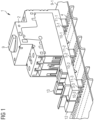
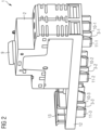
- FIG. 1 and 2 show perspective views of an exemplary embodiment of a device 1 according to the invention for a busbar system.
- an engine control unit in particular an engine starter. That in the 1 , 2
- the device 1 shown has a housing 2 in which the electrical or electromechanical structural components or components of the device 1 are integrated.
- the housing 2 has electrical connection contacts 3 on its lower side of the housing, which are designed in such a way that they can be passed through feed-through openings 4 in a cover plate 5 of a contact-protected base plate module 6 of the busbar system and contact openings 7, located below the feed-through openings 4, are evenly spaced from busbar modules provided inside the base plate module 6 8 can be plugged in to produce a direct electrical and mechanical connection to the busbar modules 8 .
- This is also shown schematically in 7 shown.
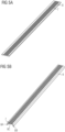
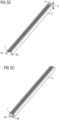
- FIGS 3, 4 show an embodiment of the base plate module 6.
- the base plate module 6 is shown with the cover plate 5 in place, while in 4 the base plate module 6 is shown with the cover plate 5 removed.
- the base plate module 6 is shown with the cover plate 5 removed.
- These different busbars 8-i each have equally spaced contact openings 7.
- the contact openings 7 contact slots in a predetermined grid are provided spaced equally from one another within the busbars 8 .
- the cover plate 5 of the base plate module 6 has rows 9-1, 9-1, 9-3 of feed-through openings 4 corresponding to the three busbars 8-1, 8-2, 8-3 provided within the base plate module 6, which are also equally spaced from one another and lie over corresponding contact openings or contact slots 7, as also schematically in FIG 7 shown.
- the housing 2 of the device 1 shown can have one or more operating elements 9 on its upper side, for example a rotary switch or the like.
- the housing 2 For each row 9-i of feed-through openings 4 within the cover plate 5 or for each row of contact openings 7 of busbars 8-i within the base plate module 6, the housing 2 has at least one corresponding electrical connection contact 3-i on its underside, as in 1 , 2 shown.
- the device 1 For a base plate module 6, as in the Figures 3, 4 is shown with and without a cover plate 5, the device 1 has three mutually parallel electrical connection contacts 3-1, 3-2, 3-3, as in FIGS 1 , 2 shown.
- the distance between the electrical connection contacts 3-1, 3-2, 3-3 corresponds to the distance between the feed-through openings 4 of the rows 9-1, 9-2, 9-3 or the distance between the underlying contact openings 7 within the Base plate module 6 provided corresponding busbars 8-1, 8-2, 8-3.
- the housing 2 of the device 1 can also have a plurality of connection contacts 3-i for each busbar 8-i. At the in the 1 , 2 In the exemplary embodiment shown, the housing 2 has two electrical connection contacts for each of the three busbars 8-1, 8-2, 8-3 on the underside of the housing.
- the number of connection contacts 3-i of device 1 per busbar 8-i can vary depending on the type of device 1.
- the device 1 can be supplied with electricity via the electrically connected busbar modules 8-i of the base plate module 6.
- busbar modules 8-i of the base plate module 6.
- three busbars 8 - 1 , 8 - 2 , 8 - 3 for three current phases L1 , L2 , L3 are provided inside the base plate module 6 .
- the device 1 communicates with other devices of the busbar system via the electrically connected busbar modules 8-1, 8-2, 8-3.
- device 1 has first electrical connection contacts for supplying power to device 1 and second electrical connection contacts for communication with other devices in the busbar system.
- the device 1 has a transceiver integrated in the housing 2, which is designed to exchange information data with other devices of the busbar system by means of power line communication, PLC, via the connection contacts 3 of the device 1 plugged into the busbar modules 8-i .
- associated contact protection ribs running parallel thereto are provided on the housing 2 of the device 1 for the electrical connection contacts 3-i.
- the electrical connection contact 3-1 provided for the first busbar 8-1 has two contact protection ribs 10-1, 11-1 arranged parallel thereto.
- the electrical connection contact 3-2 provided for the second busbar 8-2 has two parallel contact protection ribs 10-2, 11-2.
- the third electrical connection contact 3-3 of the device 1 for the third busbar 8-3 has two contact protection ribs 10-3, 11-3 arranged parallel thereto.
- feed-through opening 4 within the cover plate 5 of the base plate module 6 directly above a corresponding contact opening 7 of a busbar 8.
- the distance between the feed-through openings 4 corresponds exactly to the distance between the various contact openings 7 within the busbar 8.
- size and shape of the feed-through openings 4 preferably corresponds exactly to the size and shape of the contact openings 7 within the busbar modules 8.
- the feed-through openings 4 and the underlying contact openings 7 are designed like slots, as in FIGS Figures 3, 4 recognizable.
- the contact protection ribs 10, 11 have a guiding function in order to ensure that the housing 2 is placed on the base plate module 6 in a targeted manner.
- the contact protection ribs 10, 11 also form lateral mechanical protection for the connection contacts 3, in particular when the housing 2 of the device 1 has been removed from the base plate module 6.
- the distance between the lateral contact protection ribs 10, 11 and the electrical connection contact 3 in between preferably corresponds exactly to the distance between two feed-through openings 4 within the cover plate 5 of the base plate module 6 or the distance between two contact openings 7 within a busbar module 8, as in 7 shown.
- the grid of the electrical connection contacts 3 and the two associated contact protection ribs 10, 11 on the side thus corresponds to the grid of the feed-through openings 4 within the cover plate 5 of the base plate module 6 and the grid of the contact openings 7 within the busbar modules 8.
- the electrical connection contact 3 has two parallel arranged contact protection ribs 10, 11 Feed-through openings 4 or contact openings 7 may be provided in order to further facilitate insertion of the contact openings 3 into the base plate module 6 and to increase the mechanical stability in the inserted state.
- the electrical connection contacts 3 are V-shaped, so that they can be easily passed through the feed-through openings 4 and then establish an electrical and mechanical connection with the busbar modules 8 underneath by being inserted into their contact openings 7 .
- FIGS. 6A, 6B show different embodiment variants of electrical connection contacts 3 for connecting the electrical device 1 in contact openings or contact slots 7 of busbar modules 8-i.
- Figure 6A shows six different embodiment variants 3A to 3F for possible electrical connection contacts 3, which can be inserted through feed-through openings 4, in particular feed-through slots, into the contact openings or contact slots 7 of a busbar module 8.
- Figure 6B shows the different embodiment variants 3A to 3F of the electrical connection contacts 3-i according to FIG Figure 6A in the unplugged state.
- Figure 6B a further embodiment variant 3G of a connection contact 3.
- the connection contacts 3 are preferably designed in such a way that, in addition to the electrical contacting, they also produce a mechanical connection with the corresponding busbar module 8, as in Figure 6A recognizable.
- connection contacts 3 are preferably designed in such a way that a housing 2 of a device 1 can be inserted into corresponding busbar modules 8 and can then be pulled out again if necessary.
- the electrical connection contacts 3 can also be designed mechanically in such a way that after insertion into the busbar modules 8 they latch and the housing 2 can no longer simply be pulled out of the busbar module 8 .
- locking means are additionally attached to the housing 2 of the device 1, which can be snapped onto the cover plate 5 of the base plate module 6 and/or into locking webs of the contact-protected base plate module 6 running parallel to the busbar modules 8.
- the in the Figures 6A, 6B Connection contacts 3 shown are V-shaped, as shown in variants 3F, 3G, or finger-shaped, as shown for example in FIG. 3D.
- the connection contacts 3 can be passed through slot-shaped feed-through openings 4 in the cover plate 5 of the base plate module 6 and can be inserted into the contact openings 7 immediately below.
- the housing 2 of the device 1 in one possible embodiment has an integrally formed web 12 to which a mounting or top-hat rail 13 can be attached.
- a top-hat rail 13 is provided on the web 12 of the housing 2, which allows additional devices, for example a contactor or the like, to be mounted.
- connection contacts 3-i is provided for each busbar 8-i of the busbar system.
- the device has 1 in the in 1
- the exemplary embodiment illustrated therefore has six electrical connection contacts 3, with two electrical connection contacts being provided for one of the three busbar modules 8-i of the busbar system.
- one electrical connection contact 3 of the connection contact pair is used to supply power to the device 1 and the adjacent second electrical connection contact 3 for communication with other devices of the busbar system.
- the motor starter 1 shown can communicate in this way with other different devices of the busbar system or exchange information data via connection contacts 3 provided for this purpose.
- These different devices of the busbar system include, for example, a motor control device, a measuring device, a display device, a power pack, a fuse device, a switch disconnector, a fuse switch disconnector, an overvoltage protection device, a lightning protection device, a communication device, a residual current circuit breaker or an interference suppression device.
- the contact-protected base plate module 6 shown consists of the cover plate 5 and a lower part, both of which are firmly connected to one another.
- the upper part or the cover plate 5 is clipped onto the lower part by means of clip connections.
- the upper part or the cover plate 5 is firmly screwed to the lower part.
- the cover plate 5 can be firmly welded to the lower part.
- the cover plate 5 is riveted or glued to the lower part of the contact-protected base plate module 6 .
- Both the upper part or the cover plate 5 and the lower part consist of an electrically insulating material.
- the cover plate 5 and the lower part are made of a flame-retardant plastic.
- the electrically insulating flame retardant plastic of the top 5 and bottom of the touch proof base plate module 6 has a relatively high thermal conductivity for dissipating heat.
- the housing 2 of the device 1 is preferably made of an electrically insulating, flame-retardant plastic.
- the electrical devices 1 can be placed directly on the base plate module 6 without the need for adapter devices or the like.
- the devices or switching devices 1 each have a housing 2, on the underside of which V-shaped or finger-shaped connection contacts 3 are attached. These connection contacts 3 are used to establish an electrical connection with the electrically conductive busbar modules 8 present within the contact-protected base plate module 6.
- the connection contacts 3 of the devices 1 are designed to be self-resilient in one possible embodiment. In a further possible embodiment, the connection contacts 3 of the device 1 are externally spring-loaded.
- the front side or the cover plate 5 of the base plate module 6 has three rows 9 - i of through-openings 4 .
- the connection contacts 3 of the device 1 are designed in such a way that they can be passed through the feed-through openings 4 of the cover plate 5 and, after being passed through, can be inserted into correspondingly arranged contact openings 7 of a predetermined contact opening grid of the electrically conductive busbar modules 8 surrounded by the insulating, contact-protected base plate module 6 .
- the electrically conductive busbar modules 8 are special busbar modules 8 with contact openings 7, which also have the specified contact opening grid.
- the feed-through openings 4 and the contact openings 7 are slot-shaped.
- the lead-through openings 4 and the contact openings 7 can also be circular, elliptical, square or triangular.
- the Figures 5A, 5B , 5C, 5D show different design variants of electrically conductive busbar modules 8.
- the contact openings 7 are shaped like slits and form contact slits.
- Corresponding connection contacts 3 of the device 1 according to the invention are inserted into these in order to produce an electrical and mechanical connection.
- the lead-through openings 4 and the contact openings 7 have a predetermined spacing of 4.5 mm and can preferably be 2.2 mm wide.
- the feed-through openings 4 and contact openings 7 are contact slots and, in one possible embodiment variant, have a slot length of approximately 15 mm.
- other dimensions and divisions of the feed-through openings 4 and the contact openings 7 are also possible.
- the dimensions and distances between the connection contacts 3 of the device 1 can also vary in a corresponding manner.
- the electrically conductive busbar module 8 is flat.
- the busbar modules 8 have a U-shaped or O-shaped transverse profile.
- the contact-protected base plate module 6 has two rows 14-1, 14-2 with contours or slots that are intended to accommodate locks on the installed devices 1. These locks can secure the devices 1 against being pulled off to the front.
- the contact protection ribs 10, 11 secure the device 1 in the direction of gravity.
- a further row 15 of contours or slots is provided, in which reverse polarity protection ribs of the connected devices 1 can dip.
- the reverse polarity protection ribs are located on the underside of the 1 , 2 shown housing 2 of the device 1.
- the contours or slots of the row 15 within the upper part 5 of the touch-protected base plate module 6 prevent electrical devices 1 wrong or wrong polarized can be plugged into the contact-protected base plate module 6. Due to the special arrangement of the various feed-through slots 4 of the locking contours and the reverse polarity protection contours for the reverse polarity protection ribs of the devices 1, the entire contact-protected base plate module 6 can be equipped with electrical devices 1 without losing installation space on the left or right.
- the devices 1 can preferably be lined up without gaps on the contact-protected base plate module 6 without a gap, so that no free space remains or no space is lost on the front or end face of the contact-protected base plate module 6 .
- the touch-protected base plate module 6 offers IP20 touch protection.
- the series of coding and reverse polarity protection ribs can also reliably prevent devices 1 to be connected from being accidentally twisted.
- the devices 1 can be connected to and removed from the busbar system without the use of tools.
- a slotted screwdriver can only be used to actuate a latching element of the device 1, if necessary.
- the devices 1 of the busbar system communicate with one another by means of power line communication, PLC, via the busbars 8 contained in the contact-protected base plate module 6.
- the devices 1 each have a transceiver for exchanging information data via associated connection contacts 3.
- a frequency range from 50 to 500 kHz and/or from 16 MHz to 30 MHz is used. Data rates of up to 2.5 Mbit/sec can be achieved in the lower frequency range, while up to 14 Mbit/sec can be achieved in the upper frequency range.
- the devices 1 connected to the busbar system communicate with one another via a separate wireless radio interface.
- the communication between the device 1 and other devices 1 takes place via different communication channels, in particular by means of electrical data lines, by means of power line communication and/or by means of wireless communication via radio interfaces.
- these radio interfaces include a WLAN, a Bluetooth, a ZigBee or an RFID interface.
- the device 1 can also communicate via an external transmitter and receiver, for example a smartphone, in order to be able to exchange and set data and parameters.
- the contact-protected base plate module 6 has additional modules for neutral conductors N or PE conductors or can be expanded for data lines.
- the device 1 has corresponding connection contacts for connection to the neutral conductor N and/or to the PE conductor of the additional module.
- the device 1 according to the invention can be attached to the busbar system quickly and with relatively little effort. The assembly takes place without the use of tools.
- the contact-protected base plate module 6 offers almost complete contact protection for the user. Furthermore, this can 1
- the device 1 shown can be quickly and safely removed from the mounting plate or the contact-protected base plate module 6 as required, without the busbar modules 8-i having to be switched off from the current or voltage.
- the contact resistance between the electrical device 1 and the busbars 8-i is very low, so that the power loss generated as a result is also minimal.
- the busbars 8-i are not only used to supply power or voltage to the connected devices 1, but are also used for communication of the various devices 1 with each other.
- the contact-protected base plate module 6 is provided in a switch cabinet, with the rows of lead-through openings 4 and the corresponding rows of contact openings 7 running horizontally within the switch cabinet.
- the contact protection ribs 10, 11 serve to protect the connecting contacts 3 located in between, for example against bending or other mechanical damage.
- the contact protection ribs 10, 11 provide a mechanical holding force against gravity.
- the electrical connection contacts 3 also establish a mechanical connection with the busbar modules 8 .
Landscapes
- Engineering & Computer Science (AREA)
- Power Engineering (AREA)
- Mounting Components In General For Electric Apparatus (AREA)
- Connector Housings Or Holding Contact Members (AREA)
- Distribution Board (AREA)
- Installation Of Bus-Bars (AREA)
- Patch Boards (AREA)
- Connections Arranged To Contact A Plurality Of Conductors (AREA)
- Casings For Electric Apparatus (AREA)
- Switch Cases, Indication, And Locking (AREA)
- Clamps And Clips (AREA)
- Multi-Conductor Connections (AREA)
- Connection Or Junction Boxes (AREA)
- Details Of Connecting Devices For Male And Female Coupling (AREA)
Claims (12)
- Appareil (1) pour un système de barre omnibus,dans lequel un boîtier (2) de l'appareil (1) présente, sur un côté du boîtier, des contacts de raccordement électrique (3) qui sont conçus de manière à pouvoir être passés à travers des ouvertures de passage (4) d'un module de plaque de base (6) protégé contre les contacts accidentels du système de barres omnibus et être enfichés dans des ouvertures de contact (7) régulièrement espacées, situées en dessous des ouvertures de passage (4), de modules de barre omnibus (8) prévus à l'intérieur du module de plaque de base (6) pour établir une liaison électrique et mécanique directe avec les modules de barre omnibus,caractérisé en ce queles contacts de raccordement (3) de l'appareil (1) sont réalisés en forme de V ou de doigt ainsi qu'à élasticité propre.
- Appareil selon la revendication 1,
dans lequel des moyens d'encliquetage supplémentaires sont montés sur le boîtier (2) de l'appareil (1), lesquels peuvent être encliquetés sur une plaque de recouvrement (5) du module de plaque de base (6) et/ou dans des barrettes d'encliquetage du module de plaque de base (6) protégé contre les contacts accidentels s'étendant parallèlement aux modules de barre omnibus (8). - Appareil selon la revendication 1 ou 2,
dans lequel l'appareil (1) est un appareil électrique, électronique ou électromécanique qui est alimenté en courant par les modules de barre omnibus (8) reliés électriquement et/ou qui communique avec d'autres appareils (1) du système de barre omnibus par les modules de barre omnibus (8) reliés électriquement. - Appareil selon l'une des revendications précédentes 1 à 3, dans lequel il est prévu sur le boîtier (2) de l'appareil (1), pour les contacts de raccordement électrique (3), des nervures de protection contre le contact (10, 11) respectivement associées et s'étendant parallèlement à ceux-ci.
- Appareil selon l'une des revendications précédentes 1 à 4, dans lequel des nervures de protection contre l'inversion de polarité sont prévues sur le boîtier (2) de l'appareil (1) pour le raccordement correct au système de barre omnibus.
- Appareil selon l'une des revendications précédentes 1 à 5, dans lequel les contacts de raccordement (3) de l'appareil (1) peuvent être passés respectivement à travers des ouvertures de passage (4) en forme de fentes d'une plaque de recouvrement (5) du module de plaque de base (6) et être enfichés dans les ouvertures de contact (7) situées en dessous.
- Appareil selon l'une des revendications précédentes 1 à 6, dans lequel le boîtier (2) de l'appareil (1) présente une entretoise (12) formée sur lui, sur laquelle est monté un rail porteur ou un rail DIN (13).
- Appareil selon l'une des revendications précédentes 1 à 7, dans lequel l'appareil (1) présente des premiers contacts de raccordement électrique (3) pour l'alimentation en courant de l'appareil (1) et des deuxièmes contacts de raccordement électrique (3) pour la communication avec d'autres appareils (1) du système de barre omnibus.
- Appareil selon l'une des revendications précédentes 1 à 8, dans lequel l'appareil (1) présente un émetteur-récepteur intégré conçu pour échanger des données d'information avec d'autres appareils (1) du système de barre omnibus par communication par courant porteur en ligne, CPL, via les contacts de raccordement (3) de l'appareil (1) enfichés dans les modules de barre omnibus (8) ou via une interface radio.
- Appareil selon l'une des revendications précédentes 1 à 9, dans lequel l'appareil (1) présente :un appareil de commande de moteur,un appareil de mesure,un appareil d'affichage,un bloc d'alimentation,un dispositif de sécurité,un interrupteur-sectionneur,un interrupteur-sectionneur à fusibles,un appareil de protection contre les surtensions,un appareil de protection contre la foudre,un appareil de communication,un disjoncteur différentiel etun dispositif d'antiparasitage.
- Appareil selon l'une des revendications précédentes 4 à 10, dans lequel la distance entre deux nervures de protection latérales contre le contact (10, 11) et le contact de raccordement électrique (3) associé situé entre elles correspond à la distance entre deux ouvertures de passage (4) à l'intérieur de la plaque de recouvrement (5) du module de plaque de base (6) ou à la distance entre deux ouvertures de passage (5) à l'intérieur d'un module de barre omnibus (8), de sorte qu'une trame des contacts de raccordement électrique (3) et des deux nervures de protection latérales contre le contact (10, 11) associées correspond à la trame des ouvertures de passage (4) à l'intérieur de la plaque de recouvrement (5) du module de plaque de base (6) et à la trame des ouvertures de contact (7) à l'intérieur des modules de barre omnibus (8).
- Appareil selon la revendication 11,
dans lequel d'autres nervures de protection contre le contact (10, 11) sont prévues en parallèle dans la trame correspondante des ouvertures de passage (4) ou des ouvertures de contact (7).
Priority Applications (4)
| Application Number | Priority Date | Filing Date | Title |
|---|---|---|---|
| CN202111599139.9A CN114530716A (zh) | 2016-05-17 | 2017-05-16 | 用于母线系统的装置 |
| CN201780030499.2A CN109155471A (zh) | 2016-05-17 | 2017-05-16 | 用于母线系统的装置 |
| US16/099,859 US10700464B2 (en) | 2016-05-17 | 2017-05-16 | Device for a busbar system |
| PCT/EP2017/061668 WO2017198642A1 (fr) | 2016-05-17 | 2017-05-16 | Appareil pour système de barres omnibus |
Applications Claiming Priority (1)
| Application Number | Priority Date | Filing Date | Title |
|---|---|---|---|
| EP16169977.2A EP3246995B1 (fr) | 2016-05-17 | 2016-05-17 | Systeme de barres omnibus |
Publications (3)
| Publication Number | Publication Date |
|---|---|
| EP3246996A1 EP3246996A1 (fr) | 2017-11-22 |
| EP3246996C0 EP3246996C0 (fr) | 2023-08-23 |
| EP3246996B1 true EP3246996B1 (fr) | 2023-08-23 |
Family
ID=56014869
Family Applications (3)
| Application Number | Title | Priority Date | Filing Date |
|---|---|---|---|
| EP16169977.2A Active EP3246995B1 (fr) | 2016-05-17 | 2016-05-17 | Systeme de barres omnibus |
| EP16191898.2A Active EP3247010B1 (fr) | 2016-05-17 | 2016-09-30 | Dispositif de fixation d'un objet sur un rail |
| EP17153517.2A Active EP3246996B1 (fr) | 2016-05-17 | 2017-01-27 | Appareil pour un système de rail de barre omnibus |
Family Applications Before (2)
| Application Number | Title | Priority Date | Filing Date |
|---|---|---|---|
| EP16169977.2A Active EP3246995B1 (fr) | 2016-05-17 | 2016-05-17 | Systeme de barres omnibus |
| EP16191898.2A Active EP3247010B1 (fr) | 2016-05-17 | 2016-09-30 | Dispositif de fixation d'un objet sur un rail |
Country Status (6)
| Country | Link |
|---|---|
| US (3) | US10879642B2 (fr) |
| EP (3) | EP3246995B1 (fr) |
| CN (4) | CN109155472B (fr) |
| ES (3) | ES2811975T3 (fr) |
| PL (2) | PL3246995T3 (fr) |
| WO (3) | WO2017198484A1 (fr) |
Cited By (2)
| Publication number | Priority date | Publication date | Assignee | Title |
|---|---|---|---|---|
| WO2025087511A1 (fr) * | 2023-10-24 | 2025-05-01 | Future Systems Besitz Gmbh | Bande avec repères de position, ensemble couvercle de protection et dispositif d'installation électrique |
| WO2025087510A1 (fr) * | 2023-10-24 | 2025-05-01 | Future Systems Besitz Gmbh | Ensemble couvercle de protection tactile avec repères de position et dispositif d'installation électrique |
Families Citing this family (24)
| Publication number | Priority date | Publication date | Assignee | Title |
|---|---|---|---|---|
| PL3490349T3 (pl) | 2017-11-23 | 2022-12-27 | Wöhner GmbH & Co. KG Elektrotechnische Systeme | Aparat do zasilania szynoprzewodowego |
| EP3540872A1 (fr) | 2018-03-15 | 2019-09-18 | Wöhner Besitz GmbH | Barre omnibus hybride pour système de barres omnibus |
| GB2574727A (en) * | 2018-06-13 | 2019-12-18 | Eaton Intelligent Power Ltd | Electrical panelboard and plug-in device for such a panelboard with improved electrical insulation and modularity |
| US11095117B2 (en) * | 2018-07-20 | 2021-08-17 | Vertiv Corporation | DC-DC converters having DIN rail mounts |
| CN111682429B (zh) * | 2018-09-29 | 2022-04-05 | 胜利油田恒达电气有限责任公司 | 具有防雷击功能的变电箱的双重防雷方法 |
| DE102019109638B4 (de) * | 2019-04-11 | 2021-11-18 | Rittal Gmbh & Co. Kg | Schaltschrankanordnung mit einem Schaltschrankrahmengestell und einem auf einer Montageplatte montierten mehrpoligen Berührungsschutzmodul |
| CN112576869A (zh) * | 2019-09-27 | 2021-03-30 | 台达电子工业股份有限公司 | 电源模块 |
| BE1028102B1 (de) * | 2020-02-28 | 2021-09-27 | Phoenix Contact Gmbh & Co | Stromschienenadapter zur elektrischen Verbindung wenigstens eines Steckmoduls mit wenigstens einer Stromschiene |
| DE102020106085A1 (de) | 2020-03-06 | 2021-09-09 | Phoenix Contact Gmbh & Co. Kg | Anschlussvorrichtung und elektromechanische Baugruppe |
| US11158998B1 (en) | 2020-04-27 | 2021-10-26 | Abb Schweiz Ag | Heat sink for power supply panel |
| PL3926774T3 (pl) * | 2020-06-19 | 2023-03-06 | Wöhner Besitz Gmbh | Płyta szynoprzewodu |
| EP3926770A1 (fr) | 2020-06-19 | 2021-12-22 | Wöhner Besitz GmbH | Plaque de barre à bus allongée |
| CN111653996B (zh) * | 2020-06-27 | 2021-10-01 | 河北纳格新材料科技有限公司 | 一种石墨烯弱电线路与墙壁插线盒连接结构 |
| US11139639B1 (en) | 2020-07-09 | 2021-10-05 | Ge Aviation Systems Limited | Modular power distribution assembly and method of assembly thereof |
| CN111884073A (zh) * | 2020-07-23 | 2020-11-03 | 广东电网有限责任公司 | 分接箱通信模块的固定装置 |
| WO2022109594A1 (fr) | 2020-11-20 | 2022-05-27 | Wohner Besitz Gmbh | Porte-fusible |
| EP4184732B1 (fr) * | 2021-11-22 | 2025-03-26 | Wöhner Besitz GmbH | Module d'alimentation électrique |
| DE102023117907B4 (de) * | 2023-07-06 | 2025-01-23 | Klaus Bruchmann Gmbh | Geräteträger-modul und montagetafel-system mit einem solchen geräteträger-modul |
| CN117117583B (zh) * | 2023-09-27 | 2026-01-02 | 香江科技(集团)股份有限公司 | 一种使用开放式固定支架的滑轨式末端母线及使用方法 |
| EP4576459A1 (fr) * | 2023-12-20 | 2025-06-25 | Wöhner Besitz GmbH | Système de barre omnibus à protection tactile à double boîtier |
| US20250279634A1 (en) * | 2024-02-29 | 2025-09-04 | Abb Schweiz Ag | Expandable Panelboard Bus Assemblies and Methods of Assembling Same |
| DE102024111474A1 (de) * | 2024-04-24 | 2025-10-30 | Weidmüller Interface GmbH & Co. KG | Elektronikmodul mit einem Elektronikgehäuse mit einem Montagefuß |
| LU507363B1 (de) * | 2024-05-29 | 2025-12-01 | Phoenix Contact Gmbh & Co | Vorrichtung und System zur Energiemessung |
| US20260100558A1 (en) * | 2024-10-07 | 2026-04-09 | AUO Corporation | Power distribution system |
Citations (1)
| Publication number | Priority date | Publication date | Assignee | Title |
|---|---|---|---|---|
| US7957121B1 (en) * | 2006-08-18 | 2011-06-07 | Nichols Mitchell A | Circuit breakers and circuit breaker box |
Family Cites Families (69)
| Publication number | Priority date | Publication date | Assignee | Title |
|---|---|---|---|---|
| US3124403A (en) * | 1964-03-10 | Electrical bus conductor | ||
| US3018320A (en) * | 1955-06-13 | 1962-01-23 | Gen Electric | Electricity distributing conduit apparatus |
| US3009011A (en) | 1956-03-02 | 1961-11-14 | Gen Electric | Distribution system |
| US3182381A (en) | 1958-05-26 | 1965-05-11 | Gen Electric | Method of forming apertured hollow insulated busbars |
| US3183299A (en) | 1958-05-26 | 1965-05-11 | Gen Electric | Busway with resiliently bowed housing |
| DE19537528C2 (de) * | 1995-09-29 | 2000-01-13 | Krone Ag | Anschlußeinrichtung für die Fernmelde- und Datentechnik |
| US3096131A (en) * | 1961-01-03 | 1963-07-02 | Gen Electric | Electrical bus conductor |
| US3213403A (en) | 1961-03-24 | 1965-10-19 | Ite Circuit Breaker Ltd | Plug-in bus duct |
| US3268848A (en) | 1961-09-05 | 1966-08-23 | Gen Electric | Bus bar type electric power distribution system with formed insulating sheet housing |
| GB965290A (en) | 1961-11-10 | 1964-07-29 | Brown David Ind Ltd | New or improved machine for generating bevel and hypoid gears |
| US3346776A (en) * | 1965-12-17 | 1967-10-10 | Gen Electric | Bus bar supporting and insulating assembly having back-to-back bus bar receiving channels |
| GB1184250A (en) * | 1967-11-18 | 1970-03-11 | Amp Inc | Sealing Arrangement for Multiple Contacts |
| US3634810A (en) | 1970-02-03 | 1972-01-11 | Reynolds Metals Co | Electrical bus bar construction and method of making same |
| US4243291A (en) * | 1978-11-03 | 1981-01-06 | Alden Research Foundation | Polarized electrical outlet |
| US4567654A (en) * | 1984-04-02 | 1986-02-04 | Emhart Industries, Inc. | Bussing block |
| DE3424482A1 (de) | 1984-06-29 | 1986-01-09 | WAGO Verwaltungsgesellschaft mbH, 4950 Minden | Sammelschiene fuer stromverteiler und stromverteiler |
| JPS6215795A (ja) | 1985-07-11 | 1987-01-24 | 松下電器産業株式会社 | 誘導加熱調理器用インバ−タ |
| JPS6215795U (fr) * | 1985-07-11 | 1987-01-30 | ||
| US4758172A (en) * | 1987-10-13 | 1988-07-19 | General Electric Company | Power distribution busway system |
| DE3870437D1 (de) * | 1988-01-30 | 1992-05-27 | Weidmueller C A Gmbh Co | Montagefuss fuer reihenklemmen. |
| NL8801467A (nl) | 1988-06-07 | 1990-01-02 | Holec Syst & Componenten | Schakelkast voor elektrische installaties. |
| FR2646737B1 (fr) | 1989-05-03 | 1991-07-26 | Telemecanique | Dispositif repartiteur de puissance pour installation electrique |
| DE3933703A1 (de) | 1989-10-09 | 1991-04-18 | Pepperl & Fuchs | Stromschiene zur elektrischer kontaktierung von geraeten |
| DE4327715A1 (de) | 1993-08-18 | 1995-02-23 | Abb Patent Gmbh | Vorrichtung zum Zuführen elektrischer Energie zu wenistens einem elektrischen Installationsgerät |
| JPH08236225A (ja) * | 1994-10-28 | 1996-09-13 | Whitaker Corp:The | 電気コネクタ |
| US5607317A (en) * | 1994-12-23 | 1997-03-04 | Haworth, Inc. | Electrical powerway for furniture panel |
| AU719381B2 (en) * | 1995-01-25 | 2000-05-11 | Haworth Inc. | Modular communication cabling arrangement |
| DE19504762C2 (de) * | 1995-02-04 | 2002-08-29 | Wago Verwaltungs Gmbh | Entriegelungsvorrichtung für eine Rastbefestigung eines elektr. oder elektronischen Bauelements auf einer Tragschiene |
| DE19511350A1 (de) | 1995-03-28 | 1996-10-02 | Kloeckner Moeller Gmbh | Schienenkanalsystem einer Niederspannungs-Schaltanlage |
| DE29505258U1 (de) | 1995-03-28 | 1995-07-06 | Klöckner-Moeller GmbH, 53115 Bonn | Schottwand einer Niederspannungs-Schaltanlage |
| DE29505243U1 (de) | 1995-03-28 | 1996-07-25 | Klöckner-Moeller GmbH, 53115 Bonn | Erdungsvorrichtung für einen Einschub eines Energieverteilerschrankes |
| US5535513A (en) * | 1995-08-25 | 1996-07-16 | The Whitaker Corporation | Method for making surface mountable connectors |
| JP3147749B2 (ja) * | 1995-12-06 | 2001-03-19 | 株式会社オートネットワーク技術研究所 | 超音波溶接法 |
| JPH09320347A (ja) * | 1996-05-29 | 1997-12-12 | Harness Sogo Gijutsu Kenkyusho:Kk | 自動車用ワイヤーハーネス及びその製造 |
| JP3253541B2 (ja) * | 1996-10-25 | 2002-02-04 | アルプス電気株式会社 | フラットケーブルと端子の接続構造 |
| DE29806691U1 (de) * | 1998-04-15 | 1998-05-28 | Weidmüller Interface GmbH & Co, 32760 Detmold | Montagefuß für anreihbare Einbaugehäuse oder Klemmen |
| US6238225B1 (en) * | 1998-09-23 | 2001-05-29 | Tvm Group, Inc. | Bus bar assembly |
| EP1196838B1 (fr) * | 1999-03-30 | 2006-05-31 | Siemens Energy & Automation, Inc. | Automate programmable (plc):procede, systeme et dispositif |
| DE19957277A1 (de) | 1999-11-29 | 2001-05-31 | Abb Cmc Carl Maier Ag Schaffha | Klemmanordnung für einen Niederspannungsverteiler |
| JP2001297845A (ja) * | 2000-04-14 | 2001-10-26 | Sumitomo Wiring Syst Ltd | ケーブルリール |
| JP2002033174A (ja) * | 2000-07-17 | 2002-01-31 | Sumitomo Wiring Syst Ltd | 自動コネクタ組付装置 |
| US6431909B1 (en) * | 2000-09-28 | 2002-08-13 | Rockwell Automation Technologies, Inc. | DIN rail attachment method and apparatus |
| EP1337005B1 (fr) | 2002-02-14 | 2014-10-29 | ABB Schweiz AG | Pièces de terminaison pour un système de connecteurs à fiches |
| ES2375470T3 (es) | 2002-03-11 | 2012-03-01 | Abb Schweiz Ag | Módulo de conector para sistema de zócalo de enchufe. |
| US7219423B2 (en) * | 2002-07-15 | 2007-05-22 | Haworth, Inc. | Manufacturing process for a flex connector of an electrical system |
| CA2493697A1 (fr) * | 2002-07-15 | 2004-07-08 | Haworth, Inc. | Systeme electrique modulaire a fils rigides pour zones de bureaux |
| JP2004185852A (ja) * | 2002-11-29 | 2004-07-02 | Sumitomo Wiring Syst Ltd | ワイヤーハーネスの製造方法及び端子付電線の接続装置 |
| DE10306548B4 (de) * | 2003-02-17 | 2005-02-03 | Wöhner GmbH & Co. KG Elektrotechnische Systeme | Schutzschaltereinrichtung |
| US20060121796A1 (en) * | 2004-12-08 | 2006-06-08 | Siemens Corporation | Electric phase bus bar |
| FR2879833B1 (fr) * | 2004-12-16 | 2008-06-13 | Schneider Electric Ind Sas | Dispositif de verrouillage d'un appareil electrique sur un rail de support |
| FR2884061B1 (fr) * | 2005-03-31 | 2011-08-05 | Radiall Sa | Connecteur multicontacts |
| DE202005010601U1 (de) * | 2005-07-06 | 2006-11-16 | Weidmüller Interface GmbH & Co. KG | Modulgehäuse, insbesondere Modulsockelgehäuse, zum Aufrasten auf eine im Querschnitt hutförmige Tragschiene |
| DE102005043878A1 (de) | 2005-09-14 | 2007-03-22 | Wöhner GmbH & Co. KG Elektrotechnische Systeme | Stromschienenanschlussmodul |
| US20070228826A1 (en) * | 2006-03-31 | 2007-10-04 | Jordan Patrick D | Modular, extensible electrical and communication systems, methods, and devices |
| EP2128942B1 (fr) * | 2008-05-28 | 2011-11-23 | EATON Industries Manufacturing GmbH | Système de bus modulaire et corps de module correspondant |
| DE102009007338B3 (de) * | 2009-02-04 | 2010-07-08 | Adc Gmbh | Überspannungsschutzmagazin für eine Einrichtung der Telekommunikations- und Datentechnik |
| US7980891B2 (en) * | 2009-05-05 | 2011-07-19 | Rockwell Automation Technologies, Inc. | Integrated DIN rail attachment feature for optimized constraint |
| JP5270479B2 (ja) * | 2009-07-10 | 2013-08-21 | 三菱電機株式会社 | 電気機器の取付装置及びその取付装置を備えた回路遮断器 |
| DE102010033808B4 (de) * | 2010-08-09 | 2016-12-22 | Phoenix Contact Gmbh & Co. Kg | Reihenklemme |
| EP2461440B1 (fr) * | 2010-12-03 | 2018-05-02 | ABB Schweiz AG | Systeme d'enfichage |
| DE102011001064B3 (de) * | 2011-03-03 | 2012-04-05 | Harting Electric Gmbh & Co. Kg | Modularer Steckverbinder |
| JP6003506B2 (ja) * | 2011-10-13 | 2016-10-05 | オムロン株式会社 | 電気機器の筐体 |
| DE102013103544A1 (de) * | 2013-04-09 | 2014-10-09 | Block Transformatoren-Elektronik Gmbh | Klemmvorrichtung zur lösbaren Befestigung eines Gerätegehäuses an einer Profilschiene |
| EP3258558B1 (fr) * | 2013-10-18 | 2018-09-19 | Wöhner GmbH & Co. KG Elektrotechnische Systeme | Protection contre le contact pour barres omnibus |
| CN203760686U (zh) * | 2014-01-15 | 2014-08-06 | 江苏华联电力器材有限公司 | 一种管形母线外连接器 |
| DE202015106673U1 (de) * | 2015-12-08 | 2016-01-14 | H & B Electronic Gmbh & Co. Kg | Anreihbares Bauelement |
| CN105680266B (zh) * | 2016-04-11 | 2017-11-03 | 珠海英搏尔电气股份有限公司 | 交流电机控制器、叠层母排组件及其制作方法 |
| DE102017110696B4 (de) * | 2017-05-17 | 2025-01-30 | Hanon Systems | Motorgehäuse eines Verdichters und Verfahren zur Kontaktierung eines elektrischen Motors |
| US10367295B2 (en) * | 2017-07-11 | 2019-07-30 | Moxa Inc. | Clamping mechanism for industrial input/output device |
-
2016
- 2016-05-17 ES ES16169977T patent/ES2811975T3/es active Active
- 2016-05-17 PL PL16169977T patent/PL3246995T3/pl unknown
- 2016-05-17 EP EP16169977.2A patent/EP3246995B1/fr active Active
- 2016-09-30 PL PL16191898T patent/PL3247010T3/pl unknown
- 2016-09-30 EP EP16191898.2A patent/EP3247010B1/fr active Active
- 2016-09-30 ES ES16191898T patent/ES2831713T3/es active Active
-
2017
- 2017-01-27 ES ES17153517T patent/ES2959562T3/es active Active
- 2017-01-27 EP EP17153517.2A patent/EP3246996B1/fr active Active
- 2017-05-05 WO PCT/EP2017/060826 patent/WO2017198484A1/fr not_active Ceased
- 2017-05-05 US US16/099,617 patent/US10879642B2/en active Active
- 2017-05-05 CN CN201780031018.XA patent/CN109155472B/zh active Active
- 2017-05-16 CN CN201780030678.6A patent/CN109155505B/zh active Active
- 2017-05-16 US US16/099,588 patent/US10923850B2/en active Active
- 2017-05-16 WO PCT/EP2017/061668 patent/WO2017198642A1/fr not_active Ceased
- 2017-05-16 US US16/099,859 patent/US10700464B2/en active Active
- 2017-05-16 CN CN202111599139.9A patent/CN114530716A/zh active Pending
- 2017-05-16 CN CN201780030499.2A patent/CN109155471A/zh active Pending
- 2017-05-16 WO PCT/EP2017/061675 patent/WO2017198643A1/fr not_active Ceased
Patent Citations (1)
| Publication number | Priority date | Publication date | Assignee | Title |
|---|---|---|---|---|
| US7957121B1 (en) * | 2006-08-18 | 2011-06-07 | Nichols Mitchell A | Circuit breakers and circuit breaker box |
Cited By (2)
| Publication number | Priority date | Publication date | Assignee | Title |
|---|---|---|---|---|
| WO2025087511A1 (fr) * | 2023-10-24 | 2025-05-01 | Future Systems Besitz Gmbh | Bande avec repères de position, ensemble couvercle de protection et dispositif d'installation électrique |
| WO2025087510A1 (fr) * | 2023-10-24 | 2025-05-01 | Future Systems Besitz Gmbh | Ensemble couvercle de protection tactile avec repères de position et dispositif d'installation électrique |
Also Published As
| Publication number | Publication date |
|---|---|
| WO2017198643A1 (fr) | 2017-11-23 |
| CN109155472B (zh) | 2021-02-26 |
| WO2017198642A1 (fr) | 2017-11-23 |
| WO2017198484A9 (fr) | 2018-02-01 |
| ES2959562T3 (es) | 2024-02-27 |
| ES2811975T3 (es) | 2021-03-15 |
| US10879642B2 (en) | 2020-12-29 |
| ES2831713T3 (es) | 2021-06-09 |
| WO2017198484A1 (fr) | 2017-11-23 |
| EP3246995B1 (fr) | 2020-05-13 |
| EP3247010B1 (fr) | 2020-09-16 |
| EP3246996C0 (fr) | 2023-08-23 |
| US10923850B2 (en) | 2021-02-16 |
| US20190393640A1 (en) | 2019-12-26 |
| CN109155505B (zh) | 2021-07-27 |
| CN109155471A (zh) | 2019-01-04 |
| PL3247010T3 (pl) | 2021-03-08 |
| CN109155505A (zh) | 2019-01-04 |
| US20190115676A1 (en) | 2019-04-18 |
| CN109155472A (zh) | 2019-01-04 |
| PL3246995T3 (pl) | 2020-11-30 |
| EP3247010A1 (fr) | 2017-11-22 |
| EP3246996A1 (fr) | 2017-11-22 |
| EP3246995A1 (fr) | 2017-11-22 |
| CN114530716A (zh) | 2022-05-24 |
| US20190148870A1 (en) | 2019-05-16 |
| US10700464B2 (en) | 2020-06-30 |
Similar Documents
| Publication | Publication Date | Title |
|---|---|---|
| EP3246996B1 (fr) | Appareil pour un système de rail de barre omnibus | |
| EP2461440B1 (fr) | Systeme d'enfichage | |
| DE102006022374B4 (de) | Schaltgerät | |
| EP3111515B1 (fr) | Barrette à bornes et bloc de barrettes à bornes | |
| EP3066903B1 (fr) | Système d'assemblage de composants | |
| DE68903836T2 (de) | Verbrauchereinheiten. | |
| EP1600045A1 (fr) | Support a dispositif d'electrification | |
| EP0639877B1 (fr) | Dispositif pour alimenter en énergie électrique au moins un appareil d'installation électrique | |
| DE202013003925U1 (de) | Zusatzsockel und damit herstellbare Stecksockelbaugruppe | |
| DE102019126155A1 (de) | Stromschienenmodul und entsprechendes Anschlussmodul | |
| DE10308389A1 (de) | Rahmengestell mit einer Elektrifiziereinrichtung | |
| DE19530659C1 (de) | Niederspannungs-Sammelschienensystem | |
| DE102004037083A1 (de) | Überspannungsableiter-Anordnung mit einer als Bestandteil eines Gehäuses ausführbaren Trägerplatte | |
| DE10003349A1 (de) | Halterungseinrichtung zur Befestigung wenigstens eines elektrischen Schaltgerätes auf einer Hutprofiltragschiene | |
| DE19628957A1 (de) | Anschlußvorrichtung für elektrische Installationsgeräte | |
| DE10146503A1 (de) | Elektrische Installationsverteilung | |
| DE102023124074A1 (de) | Baukastensystem zur Ausbildung einer elektrischen Verteileranordnung, Verteilerklemmenmodul eines solchen Baukastens und elektrische Verteileranordnung | |
| DE2720220A1 (de) | Sicherungsleiste zur halterung elektrischer sicherungen | |
| DE10307352B4 (de) | Elektrifiziersystem | |
| DE102005049873A1 (de) | Überspannungsableiter-Anordnung mit einer als Bestandteil eines Gehäuses ausführbaren Trägerplatte | |
| DE102017114360B4 (de) | Spannungversorgungsvorrichtung für wenigstens ein aktives Zusatzgerät an einem Zählerplatz mit einem Sammelschienensystem sowie Verteilerschrank enthaltend eine solche Spannungsversorgungsvorrichtung | |
| DE102023117907B4 (de) | Geräteträger-modul und montagetafel-system mit einem solchen geräteträger-modul | |
| DE202007013483U1 (de) | Verbindungsklemmenblock für elektrische Mehrphasenmotoren | |
| DE202004011908U1 (de) | Überspannungsableiter-Anordnung mit einer als Bestandteil eines Gehäuses ausführbaren Trägerplatte | |
| DE2600805A1 (de) | Verbindungsschienenblock |
Legal Events
| Date | Code | Title | Description |
|---|---|---|---|
| PUAI | Public reference made under article 153(3) epc to a published international application that has entered the european phase |
Free format text: ORIGINAL CODE: 0009012 |
|
| STAA | Information on the status of an ep patent application or granted ep patent |
Free format text: STATUS: THE APPLICATION HAS BEEN PUBLISHED |
|
| AK | Designated contracting states |
Kind code of ref document: A1 Designated state(s): AL AT BE BG CH CY CZ DE DK EE ES FI FR GB GR HR HU IE IS IT LI LT LU LV MC MK MT NL NO PL PT RO RS SE SI SK SM TR |
|
| AX | Request for extension of the european patent |
Extension state: BA ME |
|
| STAA | Information on the status of an ep patent application or granted ep patent |
Free format text: STATUS: REQUEST FOR EXAMINATION WAS MADE |
|
| 17P | Request for examination filed |
Effective date: 20180704 |
|
| RBV | Designated contracting states (corrected) |
Designated state(s): AL AT BE BG CH CY CZ DE DK EE ES FI FR GB GR HR HU IE IS IT LI LT LU LV MC MK MT NL NO PL PT RO RS SE SI SK SM TR |
|
| STAA | Information on the status of an ep patent application or granted ep patent |
Free format text: STATUS: EXAMINATION IS IN PROGRESS |
|
| 17Q | First examination report despatched |
Effective date: 20190510 |
|
| GRAP | Despatch of communication of intention to grant a patent |
Free format text: ORIGINAL CODE: EPIDOSNIGR1 |
|
| STAA | Information on the status of an ep patent application or granted ep patent |
Free format text: STATUS: GRANT OF PATENT IS INTENDED |
|
| INTG | Intention to grant announced |
Effective date: 20230316 |
|
| P01 | Opt-out of the competence of the unified patent court (upc) registered |
Effective date: 20230517 |
|
| GRAS | Grant fee paid |
Free format text: ORIGINAL CODE: EPIDOSNIGR3 |
|
| GRAA | (expected) grant |
Free format text: ORIGINAL CODE: 0009210 |
|
| STAA | Information on the status of an ep patent application or granted ep patent |
Free format text: STATUS: THE PATENT HAS BEEN GRANTED |
|
| AK | Designated contracting states |
Kind code of ref document: B1 Designated state(s): AL AT BE BG CH CY CZ DE DK EE ES FI FR GB GR HR HU IE IS IT LI LT LU LV MC MK MT NL NO PL PT RO RS SE SI SK SM TR |
|
| REG | Reference to a national code |
Ref country code: GB Ref legal event code: FG4D Free format text: NOT ENGLISH |
|
| REG | Reference to a national code |
Ref country code: CH Ref legal event code: EP |
|
| REG | Reference to a national code |
Ref country code: DE Ref legal event code: R096 Ref document number: 502017015250 Country of ref document: DE |
|
| REG | Reference to a national code |
Ref country code: IE Ref legal event code: FG4D Free format text: LANGUAGE OF EP DOCUMENT: GERMAN |
|
| U01 | Request for unitary effect filed |
Effective date: 20230919 |
|
| U07 | Unitary effect registered |
Designated state(s): AT BE BG DE DK EE FI FR IT LT LU LV MT NL PT SE SI Effective date: 20230925 |
|
| P04 | Withdrawal of opt-out of the competence of the unified patent court (upc) registered |
Effective date: 20230920 |
|
| U1N | Appointed representative for the unitary patent procedure changed after the registration of the unitary effect |
Representative=s name: BRATOVIC, NINO MARIA; DE |
|
| PG25 | Lapsed in a contracting state [announced via postgrant information from national office to epo] |
Ref country code: GR Free format text: LAPSE BECAUSE OF FAILURE TO SUBMIT A TRANSLATION OF THE DESCRIPTION OR TO PAY THE FEE WITHIN THE PRESCRIBED TIME-LIMIT Effective date: 20231124 |
|
| PG25 | Lapsed in a contracting state [announced via postgrant information from national office to epo] |
Ref country code: IS Free format text: LAPSE BECAUSE OF FAILURE TO SUBMIT A TRANSLATION OF THE DESCRIPTION OR TO PAY THE FEE WITHIN THE PRESCRIBED TIME-LIMIT Effective date: 20231223 |
|
| PG25 | Lapsed in a contracting state [announced via postgrant information from national office to epo] |
Ref country code: RS Free format text: LAPSE BECAUSE OF FAILURE TO SUBMIT A TRANSLATION OF THE DESCRIPTION OR TO PAY THE FEE WITHIN THE PRESCRIBED TIME-LIMIT Effective date: 20230823 Ref country code: NO Free format text: LAPSE BECAUSE OF FAILURE TO SUBMIT A TRANSLATION OF THE DESCRIPTION OR TO PAY THE FEE WITHIN THE PRESCRIBED TIME-LIMIT Effective date: 20231123 Ref country code: IS Free format text: LAPSE BECAUSE OF FAILURE TO SUBMIT A TRANSLATION OF THE DESCRIPTION OR TO PAY THE FEE WITHIN THE PRESCRIBED TIME-LIMIT Effective date: 20231223 Ref country code: HR Free format text: LAPSE BECAUSE OF FAILURE TO SUBMIT A TRANSLATION OF THE DESCRIPTION OR TO PAY THE FEE WITHIN THE PRESCRIBED TIME-LIMIT Effective date: 20230823 Ref country code: GR Free format text: LAPSE BECAUSE OF FAILURE TO SUBMIT A TRANSLATION OF THE DESCRIPTION OR TO PAY THE FEE WITHIN THE PRESCRIBED TIME-LIMIT Effective date: 20231124 |
|
| REG | Reference to a national code |
Ref country code: ES Ref legal event code: FG2A Ref document number: 2959562 Country of ref document: ES Kind code of ref document: T3 Effective date: 20240227 |
|
| PG25 | Lapsed in a contracting state [announced via postgrant information from national office to epo] |
Ref country code: PL Free format text: LAPSE BECAUSE OF FAILURE TO SUBMIT A TRANSLATION OF THE DESCRIPTION OR TO PAY THE FEE WITHIN THE PRESCRIBED TIME-LIMIT Effective date: 20230823 |
|
| U20 | Renewal fee for the european patent with unitary effect paid |
Year of fee payment: 8 Effective date: 20240131 |
|
| PG25 | Lapsed in a contracting state [announced via postgrant information from national office to epo] |
Ref country code: SM Free format text: LAPSE BECAUSE OF FAILURE TO SUBMIT A TRANSLATION OF THE DESCRIPTION OR TO PAY THE FEE WITHIN THE PRESCRIBED TIME-LIMIT Effective date: 20230823 Ref country code: RO Free format text: LAPSE BECAUSE OF FAILURE TO SUBMIT A TRANSLATION OF THE DESCRIPTION OR TO PAY THE FEE WITHIN THE PRESCRIBED TIME-LIMIT Effective date: 20230823 Ref country code: CZ Free format text: LAPSE BECAUSE OF FAILURE TO SUBMIT A TRANSLATION OF THE DESCRIPTION OR TO PAY THE FEE WITHIN THE PRESCRIBED TIME-LIMIT Effective date: 20230823 Ref country code: SK Free format text: LAPSE BECAUSE OF FAILURE TO SUBMIT A TRANSLATION OF THE DESCRIPTION OR TO PAY THE FEE WITHIN THE PRESCRIBED TIME-LIMIT Effective date: 20230823 |
|
| REG | Reference to a national code |
Ref country code: DE Ref legal event code: R097 Ref document number: 502017015250 Country of ref document: DE |
|
| PLBE | No opposition filed within time limit |
Free format text: ORIGINAL CODE: 0009261 |
|
| STAA | Information on the status of an ep patent application or granted ep patent |
Free format text: STATUS: NO OPPOSITION FILED WITHIN TIME LIMIT |
|
| 26N | No opposition filed |
Effective date: 20240524 |
|
| PG25 | Lapsed in a contracting state [announced via postgrant information from national office to epo] |
Ref country code: MC Free format text: LAPSE BECAUSE OF FAILURE TO SUBMIT A TRANSLATION OF THE DESCRIPTION OR TO PAY THE FEE WITHIN THE PRESCRIBED TIME-LIMIT Effective date: 20230823 |
|
| PG25 | Lapsed in a contracting state [announced via postgrant information from national office to epo] |
Ref country code: MC Free format text: LAPSE BECAUSE OF FAILURE TO SUBMIT A TRANSLATION OF THE DESCRIPTION OR TO PAY THE FEE WITHIN THE PRESCRIBED TIME-LIMIT Effective date: 20230823 |
|
| GBPC | Gb: european patent ceased through non-payment of renewal fee |
Effective date: 20240127 |
|
| PG25 | Lapsed in a contracting state [announced via postgrant information from national office to epo] |
Ref country code: GB Free format text: LAPSE BECAUSE OF NON-PAYMENT OF DUE FEES Effective date: 20240127 |
|
| PG25 | Lapsed in a contracting state [announced via postgrant information from national office to epo] |
Ref country code: GB Free format text: LAPSE BECAUSE OF NON-PAYMENT OF DUE FEES Effective date: 20240127 |
|
| P05 | Withdrawal of opt-out of the competence of the unified patent court (upc) changed |
Free format text: CASE NUMBER: APP_574328/2023 Effective date: 20230925 |
|
| PG25 | Lapsed in a contracting state [announced via postgrant information from national office to epo] |
Ref country code: IE Free format text: LAPSE BECAUSE OF NON-PAYMENT OF DUE FEES Effective date: 20240127 |
|
| U20 | Renewal fee for the european patent with unitary effect paid |
Year of fee payment: 9 Effective date: 20241225 |
|
| PG25 | Lapsed in a contracting state [announced via postgrant information from national office to epo] |
Ref country code: IE Free format text: LAPSE BECAUSE OF NON-PAYMENT OF DUE FEES Effective date: 20240127 |
|
| PGFP | Annual fee paid to national office [announced via postgrant information from national office to epo] |
Ref country code: CH Payment date: 20250201 Year of fee payment: 9 |
|
| PG25 | Lapsed in a contracting state [announced via postgrant information from national office to epo] |
Ref country code: CY Free format text: LAPSE BECAUSE OF FAILURE TO SUBMIT A TRANSLATION OF THE DESCRIPTION OR TO PAY THE FEE WITHIN THE PRESCRIBED TIME-LIMIT; INVALID AB INITIO Effective date: 20170127 |
|
| PG25 | Lapsed in a contracting state [announced via postgrant information from national office to epo] |
Ref country code: HU Free format text: LAPSE BECAUSE OF FAILURE TO SUBMIT A TRANSLATION OF THE DESCRIPTION OR TO PAY THE FEE WITHIN THE PRESCRIBED TIME-LIMIT; INVALID AB INITIO Effective date: 20170127 |
|
| PG25 | Lapsed in a contracting state [announced via postgrant information from national office to epo] |
Ref country code: TR Free format text: LAPSE BECAUSE OF FAILURE TO SUBMIT A TRANSLATION OF THE DESCRIPTION OR TO PAY THE FEE WITHIN THE PRESCRIBED TIME-LIMIT Effective date: 20230823 |
|
| U20 | Renewal fee for the european patent with unitary effect paid |
Year of fee payment: 10 Effective date: 20251202 |
|
| REG | Reference to a national code |
Ref country code: CH Ref legal event code: R14 Free format text: ST27 STATUS EVENT CODE: U-0-0-R10-R14 (AS PROVIDED BY THE NATIONAL OFFICE) Effective date: 20260130 |
|
| REG | Reference to a national code |
Ref country code: CH Ref legal event code: U11 Free format text: ST27 STATUS EVENT CODE: U-0-0-U10-U11 (AS PROVIDED BY THE NATIONAL OFFICE) Effective date: 20260201 |
|
| U1K | Transfer of rights of the unitary patent after the registration of the unitary effect |
Owner name: WOEHNER BESITZ GMBH; DE |
|
| PGFP | Annual fee paid to national office [announced via postgrant information from national office to epo] |
Ref country code: ES Payment date: 20260217 Year of fee payment: 10 |