EP3248910B1 - Sensorvorrichtung zur erfassung von mit einer schüttung eines abfallsammelfahrzeugs gekoppelten abfallbehältern - Google Patents
Sensorvorrichtung zur erfassung von mit einer schüttung eines abfallsammelfahrzeugs gekoppelten abfallbehältern Download PDFInfo
- Publication number
- EP3248910B1 EP3248910B1 EP17170088.3A EP17170088A EP3248910B1 EP 3248910 B1 EP3248910 B1 EP 3248910B1 EP 17170088 A EP17170088 A EP 17170088A EP 3248910 B1 EP3248910 B1 EP 3248910B1
- Authority
- EP
- European Patent Office
- Prior art keywords
- sensor device
- levers
- refuse
- collection vehicle
- coupled
- Prior art date
- Legal status (The legal status is an assumption and is not a legal conclusion. Google has not performed a legal analysis and makes no representation as to the accuracy of the status listed.)
- Active
Links
- 229920002994 synthetic fiber Polymers 0.000 claims 1
- 239000002699 waste material Substances 0.000 description 45
- 239000004033 plastic Substances 0.000 description 2
- 238000002604 ultrasonography Methods 0.000 description 2
- 238000011109 contamination Methods 0.000 description 1
- 230000001419 dependent effect Effects 0.000 description 1
- 238000011161 development Methods 0.000 description 1
- 230000018109 developmental process Effects 0.000 description 1
- 230000002349 favourable effect Effects 0.000 description 1
- 239000002184 metal Substances 0.000 description 1
- 239000012858 resilient material Substances 0.000 description 1
- 230000000284 resting effect Effects 0.000 description 1
- 239000000725 suspension Substances 0.000 description 1
Images

Classifications
-
- B—PERFORMING OPERATIONS; TRANSPORTING
- B65—CONVEYING; PACKING; STORING; HANDLING THIN OR FILAMENTARY MATERIAL
- B65F—GATHERING OR REMOVAL OF DOMESTIC OR LIKE REFUSE
- B65F3/00—Vehicles particularly adapted for collecting refuse
- B65F3/02—Vehicles particularly adapted for collecting refuse with means for discharging refuse receptacles thereinto
- B65F3/04—Linkages, pivoted arms, or pivoted carriers for raising and subsequently tipping receptacles
Definitions
- the invention relates to a sensor device for detecting waste containers coupled to a bed of a refuse collection vehicle, with a plurality of levers, the sensor device being designed such that a waste container coupled to the bed interacts with at least one lever and, depending on the type, size and / or position of the waste container on the bed of waste containers can interact with different levers.
- Loading devices for refuse collection vehicles such as, for example, side loaders are known from the prior art, in which, when using refuse bins with identification systems, appropriate signal transmitters are required to identify the refuse bin or the refuse bin type.
- the signal transmitters or sensor devices must reliably detect whether one or more garbage cans hang on the loading device and / or what sizes or what type of garbage cans or waste containers are involved.
- the state of the Technology encompasses a wide variety of systems that function without contact on the basis of, for example, ultrasound or laser beams and in which corresponding identification marks are attached to a waste container and can be recognized by a corresponding readout device.
- the identification marks contain the information required for operation, such as the type of the respective waste collection container or its identification number, by means of which the waste container can be assigned to an owner.
- a disadvantage of the systems known from the prior art is that, because of the relatively high cost of installing such systems, there is generally only a limited distinction or garbage can identification between two-wheeled and four-wheeled containers. Because it can be associated with disproportionate costs to set the known systems to more than two different waste container sizes, in which corresponding identification marks can be arranged at different locations on the waste containers. Associated with this is the problem that if the container is deliberately incorrectly arranged or labeled with incorrect identification marks, the identification and thus the charge calculation for emptying the container can be bypassed or manipulated.
- a sensor device for detecting a waste container coupled to a bed of a refuse collection vehicle with a lever is already known, to which a spring element and a proximity switch is assigned, the sensor device being designed such that the presence or absence of the comb strip of a refuse container can be determined.
- the object of the invention is to provide a device which makes it easy to identify and / or type garbage cans when they are emptied by means of a refuse collection vehicle.
- a sensor device for detecting waste containers coupled to a bed of a refuse collection vehicle, each lever being assigned a spring element with at least one contact switch provided therein or thereon, the corresponding contact switch being switched when a lever is moved, the levers being on a common axis are mounted and wherein the axis and the spring elements are arranged on the same component.
- waste containers in the present case, this can mean a single waste container coupled to the filling or also a plurality of waste containers correspondingly coupled at the same time.
- the wording captures the case in which different waste containers are coupled to the filling at different times.
- a controller which can be coupled accordingly to the sensor device can contain information which makes it possible to determine the type of waste container or its type, size or position on the basis of the switched contact switches. For example, a plurality of switched contact switches can identify a larger waste container, while only a few switched contact switches or only a single switched contact switch identifies a smaller type of waste container. This means that there is no need for expensive laser or ultrasound sensor devices that are prone to contamination, which devices must also be able to detect different areas of the waste container depending on the size of the waste container. It is furthermore advantageously no longer possible to deceive the sensor device of the detected waste container type by simply re-declaring the waste container or by applying incorrect identification marks.
- the spring element is made of plastic, in particular rubber. This enables a particularly simple spring-loaded mounting of the levers, which is not very sensitive to dirt or damage.
- the levers are pressed by means of the spring elements against waste containers resting on the sensor device, which ensures, for example, that the contact switches are switched on when the waste containers are present and that the contact switches are switched off when the waste containers are not present.
- the levers are mounted on a common axis.
- the common axis enables the sensor device to be manufactured particularly simply and therefore inexpensively.
- the common axis ensures a uniform mounting of the levers, which advantageously enables the contact switches to be switched easily and homogeneously and the levers can be easily and uniformly spaced from a particularly planar wall of a waste container.
- levers are provided.
- a different number of levers can also be used, a large part of the usual types of waste containers being sufficiently distinguishable with seven levers.
- the levers can be arranged between their spring elements and the waste container interacting with them.
- the elements are thus separated from the side of the sensor device facing the waste container by the levers, which ensures a certain protection of the spring elements and the contact switches associated with them from the container or other external influences.
- the axis and the spring elements are arranged on the same component, in particular screwed to the same component. This results in a further advantageously particularly simple design of the sensor device, which enables a favorable embodiment of the invention.
- a common component for fixing the axle and spring elements also simplifies a sufficiently rigid design of the device, which is conducive to the signal quality of the contact switches.
- the invention also relates to a refuse collection vehicle with a sensor device according to the invention for detecting the type, size and / or position of a refuse container coupled to its bed.
- the sensor device according to the invention can be coupled to the refuse collection vehicle and / or to the bed of the refuse collection vehicle in such a way that the type of refuse container of a refuse container coupled to the refill can be detected.
- the levers of the sensor device are arranged or aligned in the direction of the region of the bed in which the waste container extends in the state coupled to the bed.
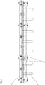
- Figure 1 shows a perspective view of a sensor device, which is formed here in the form of a strip and comprises seven levers 1.
- the levers 1 are each connected via a spring element 2 to at least one contact switch 3 provided therein or thereon.
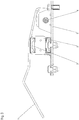
- the contact switch 3 is in Figure 3 demonstrated.
- the corresponding contact switch 3 When one of the levers 1 is moved or pivoted about the axis 4, the corresponding contact switch 3 is switched, and a correspondingly generated switching signal can be forwarded to a controller which can determine the type, size and / or position of the waste container on the basis of the generated signal.
- the number of signals generated plays a role, with a larger waste container moving more lever 1 and thus generating more signals than a smaller waste container.
- the information about, for example, the size of the waste container can be used to calculate the costs for the disposal of the waste contained in the corresponding waste container.
- the device is designed such that a waste container coupled to the bed, not shown, interacts with at least one of the levers 1, different levers 1 being able to interact with the waste container depending on the type, size and / or position of the waste container.
- the levers 1 can be arranged so that they protrude outwards from the structure of the sensor device.
- the spring elements 2 can be made of plastic, in particular rubber or also from other resilient materials or components. Metal springs for suspension or for the resilient mounting of the levers 1 are conceivable, for example. It is also conceivable to use combined spring elements 2 in which different spring components form a single spring element 2.
- the common axis 4 of the levers 1 can run along the entire sensor device and be approximately as long as the length of the arrangement of all the levers 1.
- levers 1 are mounted on an axle 4.
- deviating numbers of levers 1 are also conceivable.
- the spring elements 2 are protected by the levers 1 arranged so that they do not come into contact with the waste containers themselves and can be damaged or disturbed.
- the spring elements 2 are provided between a component 5 and the levers 1, the axis 4 and the spring elements 2 being connected to the same component 5, in particular being screwed together.
- the device can be produced in a particularly torsion-resistant and simple manner, which improves the functioning of the contact switches.
- the sensor device according to the invention can be delimited on one side by the component 5 and on the opposite side by the levers 1, wherein the spring elements 2 and the axis 4 can extend between the component 5, which can be referred to as mounting plate 5, and the levers 1 ,
- the sensor device is thus based on a simple mechanical principle in which the levers 1 are suspended on the common axis 4 and, when they come into contact with a waste container, are pressed with little force against a spring or against the spring elements 2 and the contact switches 3 can thus be actuated ,
- the lever 1 touches the wall of a waste container, the spring element 2 is pressed in, as a result of which a contact is closed inside the spring element 2 or on the spring element 2.
- Each of the mechanical levers 1 operates its own spring element 2 or switching element, each spring element 2 or switching element being guided to its own input of an electronic control, so that the combination of the actuated and non-actuated spring elements 2 or switching elements depends on the type and size and / or position of the container hanging on the bed of the refuse collection vehicle can be closed.
- Figure 2 shows a front view of the sensor device according to the invention, in which the axis 4 is shown with a partially broken line.
- the axis 4 can run over the entire or almost the entire width of the sensor device.
- the axis 4 can be above the spring elements 2 and / or parallel to them Extension direction.
- the levers 1 can be substantially T-shaped, the foot region of the lever 1 interacting with the respective spring element 2 when the lever 1 comes into contact with a waste container.
- the transverse region of the T-shaped lever 1 can be coupled to the axis 4.
- Figure 3 shows an enlarged view of a lever 1, which is coupled to the mounting plate 5 via the axis 4 shown in the profile.
- the lever 1 can be pretensioned by means of the spring element 2 and coupled to the mounting plate such that it is in constant contact with the spring element 2.
- a contact switch 3 is provided on or in the spring element 2 and is switched against the mounting plate 5 when the lever 1 is moved. This generates a signal which indicates the contact of the lever 1 with a waste container.
Landscapes
- Engineering & Computer Science (AREA)
- Mechanical Engineering (AREA)
- Refuse-Collection Vehicles (AREA)
Description
- Die Erfindung betrifft eine Sensorvorrichtung zur Erfassung von mit einer Schüttung eines Abfallsammelfahrzeugs gekoppelten Abfallbehältern, mit einer Mehrzahl an Hebeln, wobei die Sensorvorrichtung so ausgebildet ist, dass ein an der Schüttung gekoppelter Abfallbehälter mit wenigstens einem Hebel wechselwirkt und wobei je nach Art, Größe und/oder Position des Abfallbehälters an der Schüttung der Abfallbehälter mit unterschiedlichen Hebeln wechselwirken kann.
- Aus dem Stand der Technik sind Beladeeinrichtungen für Abfallsammelfahrzeuge wie beispielsweise Seitenlader bekannt, bei denen bei der Nutzung von Mülltonnen mit Identifikationssysteme zur Identifikation der Mülltonne bzw. des Mülltonnentyps entsprechende Signalgeber benötigt werden. Die Signalgeber bzw. Sensorvorrichtungen müssen zuverlässig erkennen, ob eine oder mehrere Mülltonnen an der Beladeeinrichtung hängen und/oder um welche Größen bzw. um welchen Typ von Mülltonnen bzw. Abfallbehältern es sich handelt. Der Stand der Technik umfasst dabei unterschiedlichste Systeme, die berührungslos auf der Basis von beispielsweise Ultraschall oder Laserstrahlen funktionieren und bei denen entsprechende Identifikationsmarken an einem Abfallbehälter angebracht werden, die über eine entsprechende Auslesevorrichtung erkannt werden können. Die Identifikationsmarken enthalten dabei die zum Betrieb erforderlichen Informationen wie beispielsweise den Typ des jeweiligen Abfallsammelbehälters oder dessen Identifikationsnummer mittels der der Abfallbehälter einem Eigentümer zugeordnet werden kann.
- Nachteilig an den aus dem Stand der Technik bekannten Systemen ist, dass aufgrund der relativ hohen Kosten für die Einrichtung derartige Systeme in der Regel nur eine eingeschränkte Unterscheidung bzw. Mülltonnenidentifikation zwischen Zweirad- und Vierradbehältern stattfindet. Denn es kann mit unverhältnismäßigen Kosten verbunden sein, die bekannten Systeme auf mehr als zwei unterschiedliche Abfallbehältergrößen einzustellen, bei denen entsprechende Identifikationsmarken an voneinander abweichenden Stellen an den Abfallbehältern angeordnet sein können. Damit verbunden ist das Problem, dass bei gewollt falscher Anordnung bzw. Kennzeichnung der Behälter mit falschen Identifikationsmarken die Identifikation und damit die Gebührenberechnung für die Entleerung der Behälter umgangen oder manipuliert werden kann.
- Aus der
EP 0 728 683 A ist bereits eine Sensorvorrichtung zur Erfassung eines an einer Schüttung eines Abfallsammelfahrzeuges gekoppelten Abfallbehälters mit einem Hebel bekannt, dem ein Federelement und ein Näherungsschalter zugeordnet ist, wobei die Sensorvorrichtung so ausgebildet ist, dass das Vorhandensein oder Fehlen der Kammleiste eines Abfallbehälters ermittelt werden kann. - Aus der
EP 0 955 252 A ist eine Sensorvorrichtung nach dem Oberbegriff des Anspruchs 1 bekannt. - Aufgabe der Erfindung ist es, eine Vorrichtung bereitzustellen, die es auf eine einfache Art ermöglicht, Mülltonnen bei deren Entleerung mittels eines Abfallsammelfahrzeugs zu identifizieren und/oder zu typisieren.
- Diese Aufgabe wird erfindungsgemäß durch eine Sensorvorrichtung mit den Merkmalen des Anspruchs 1 gelöst. Vorteilhafte Weiterbildungen sind Gegenstand der Unteransprüche. Demnach ist eine Sensorvorrichtung zur Erfassung von mit einer Schüttung eines Abfallsammelfahrzeugs gekoppelten Abfallbehältern vorgesehen, wobei jedem Hebel ein Federelement mit wenigstens einem darin oder daran vorgesehenem Kontaktschalter zugeordnet ist, wobei bei Bewegen eines Hebels der entsprechende Kontaktschalter geschaltet wird, wobei die Hebel an einer gemeinsame Achse gelagert sind und wobei die Achse und die Federelemente an demselben Bauteil angeordnet sind.
- Wenn vorliegend von Abfallbehältern die Rede ist, dann kann damit ein einzelner mit der Schüttung gekoppelter Abfallbehälter oder auch mehrere gleichzeitig entsprechend gekoppelte Abfallbehälter gemeint sein. Insbesondere ist durch die Formulierung der Fall erfasst, in dem unterschiedliche Abfallbehälter zeitlich versetzt mit der Schüttung gekoppelt sind.
- Eine entsprechend mit der Sensorvorrichtung koppelbare Steuerung kann dabei Informationen enthalten, welche es ermöglichen, den Typ des Abfallbehälters bzw. dessen Art, Größe oder Position anhand der geschalteten Kontaktschalter zu ermitteln. Beispielsweise kann eine Vielzahl von geschalteten Kontaktschaltern einen größeren Abfallbehälter identifizieren, während nur wenige geschaltete Kontaktschalter oder nur ein einzelner geschalteter Kontaktschalter einen kleineren Abfallbehältertyp identifiziert. Somit kann auf teure und für Verschmutzungen anfällige Laser- oder Ultraschallsensorvorrichtungen verzichtet werden, welche darüber hinaus je nach Abfallbehältergröße unterschiedliche Bereiche des Abfallbehälters erfassen können müssen. Weiterhin vorteilhaft ist es nicht mehr möglich durch einfaches Umdeklarieren der Abfallbehälter bzw. durch Anbringen falsche Identifikationsmarken die Sensorvorrichtung über den erfassten Abfallbehältertyp zu täuschen.
- In einer bevorzugten Ausführung ist denkbar, dass das Federelement aus Kunststoff, insbesondere aus Gummi hergestellt ist. Damit ist eine besonders einfache gefederte Lagerung der Hebel möglich, die wenig empfindlich gegen Verschmutzungen oder Beschädigungen ist. Die Hebel werden dabei mittels der Federelemente gegen an der Sensorvorrichtung anliegende Abfallbehälter gedrückt, wodurch beispielsweise ein Einschalten der Kontaktschalter bei anliegendem Abfallbehälter und ein Ausschalten der Kontaktschalter bei nicht anliegendem Abfallbehälter gewährleistet ist.
- Erfindungsgemäß sind die Hebel an einer gemeinsamen Achse gelagert. Die gemeinsame Achse ermöglicht es dabei die Sensorvorrichtung besonders einfach und damit kostengünstig zu fertigen. Gleichzeitig gewährleistet die gemeinsame Achse eine gleichmäßige Lagerung der Hebel, wodurch die Schaltung der Kontaktschalter vorteilhaft einfach homogen ermöglicht ist und die Hebel auf einfache Weise gleichmäßig beabstandet von einer insbesondere planaren Wandung eines Abfallbehälters anordenbar sind.
- In einer weiteren bevorzugten Ausführung ist denkbar, dass sieben Hebel vorgesehen sind. Es kann auch eine davon abweichende Zahl von Hebeln eingesetzt werden, wobei ein großer Teil der üblichen Abfallbehältertypen hinreichend mit sieben Hebeln unterscheidbar ist.
- Die Hebel können zwischen ihren Federelementen und den mit ihnen wechselwirkenden Abfallbehälter angeordnet sein.
- Die Elemente sind somit von der dem Abfallbehälter zugewandten Seite der Sensorvorrichtung durch die Hebel getrennt, wodurch ein gewisser Schutz der Federelemente und der ihnen zugeordneten Kontaktschalter vor dem Behälter bzw. vor sonstigen äußeren Einflüssen gewährleistet ist.
- Erfindungsgemäß sind die Achse und die Federelemente an demselben Bauteil angeordnet, insbesondere mit demselben Bauteil verschraubt. Hierdurch ergibt sich eine weiter vorteilhaft besonders einfache Bauart der Sensorvorrichtung, welche eine günstige Ausführung der Erfindung ermöglicht. Auch vereinfacht ein gemeinsames Bauteil zur Fixierung von Achse und Federelementen eine hinreichend steife Ausführung der Vorrichtung, welche der Signalqualität der Kontaktschalter förderlich ist.
- Die Erfindung betrifft auch ein Abfallsammelfahrzeug mit einer erfindungsgemäßen Sensorvorrichtung zur Erfassung der Art, Größe und/oder Position eines an seiner Schüttung gekoppelten Abfallbehälters. Die erfindungsgemäße Sensorvorrichtung ist dabei so mit dem Abfallsammelfahrzeug und/oder mit der Schüttung des Abfallsammelfahrzeugs koppelbar, dass die Erfassung des Abfallbehältertyps eines mit der Schüttung gekoppeltem Abfallbehälters möglich ist. Hierzu sind die Hebel der Sensorvorrichtung in Richtung auf den Bereich der Schüttung angeordnet bzw. ausgerichtet, in dem sich der Abfallbehälter im mit der Schüttung gekoppeltem Zustand erstreckt.
- Weitere Einzelheiten und Vorteile der Erfindung sind anhand der Figuren aufgezeigt. Dabei zeigen:
- Figuren 1, 2:
- unterschiedliche Ansichten einer erfindungsgemäßen Sensorvorrichtung; und
- Figur 3:
- Seitenansicht eines Hebels einer erfindungsgemäßen Sensorvorrichtung mit weiteren Komponenten der Vorrichtung.
-
Figur 1 zeigt eine perspektivische Ansicht einer Sensorvorrichtung, die hierbei in Leistenform ausgebildet ist und sieben Hebel 1 umfasst. Die Hebel 1 sind dabei über jeweils ein Federelement 2 mit wenigstens einem darin oder daran vorgesehenen Kontaktschalter 3 in Verbindung. Der Kontaktschalter 3 ist inFigur 3 aufgezeigt. - Bei Bewegen bzw. Verschwenken eines der Hebel 1 um die Achse 4 wird der entsprechende Kontaktschalter 3 geschaltet, und ein entsprechend erzeugtes Schaltsignal kann an eine Steuerung weitergeleitet werden, die die Art, Größe und/oder Position des Abfallbehälters anhand des erzeugten Signals bestimmen kann. Insbesondere spielt hierbei die Anzahl der erzeugten Signale eine Rolle, wobei ein größerer Abfallbehälter mehr Hebel 1 bewegt und damit mehr Signale erzeugt, als ein kleinerer Abfallbehälter. Die Information über beispielsweise die Größe des Abfallbehälters kann dazu genutzt werden um die Kosten für die Entsorgung des in dem entsprechenden Abfallbehälter enthaltenen Mülls zu berechnen.
- Die Vorrichtung ist so ausgebildet, dass ein an der nicht gezeigten Schüttung gekoppelter Abfallbehälter mit wenigstens einem der Hebel 1 wechselwirkt, wobei entsprechend je nach Art, Größe und/oder Position des Abfallbehälters unterschiedliche Hebel 1 mit dem Abfallbehälter wechselwirken können. Die Hebel 1 können dabei so angeordnet sein, dass sie aus dem Gefüge der Sensorvorrichtung nach außen hervorstehen.
- Die Federelemente 2 können aus Kunststoff, insbesondere Gummi oder auch aus sonstigen federnden Materialien bzw. Bauteilen hergestellt sein. Denkbar sind beispielsweise Metallfedern zur Federung bzw. zur federnden Lagerung der Hebel 1. Ebenso ist es denkbar kombinierte Federelemente 2 einzusetzen, bei denen unterschiedliche Federkomponenten ein einzelnes Federelement 2 bilden.
- Die gemeinsame Achse 4 der Hebel 1 kann entlang der gesamten Sensorvorrichtung verlaufen und in etwa so lang sein wie die Länge der Anordnung aller Hebel 1.
- In dem in den Figuren gezeigten Ausführungsbeispiel sind sieben Hebel 1 an einer Achse 4 gelagert. Denkbar sind dabei aber auch davon abweichende Anzahlen von Hebeln 1. Wie in den Figuren erkennbar, sind die Federelemente 2 geschützt durch die Hebel 1 angeordnet, sodass sie nicht mit den Abfallbehältern selbst in Kontakt kommen und dabei beschädigt oder gestört werden können. Die Federelemente 2 sind dabei zwischen einem Bauteil 5 und den Hebeln 1 vorgesehen, wobei die Achse 4 und die Federelemente 2 mit demselben Bauteil 5 verbunden, insbesondere verschraubt sein können. Hierdurch kann die Vorrichtung besonders verwindungssteif und einfach hergestellt werden, wodurch das Funktionieren der Kontaktschalter verbessert wird.
- Die erfindungsgemäße Sensorvorrichtung kann an einer Seite von dem Bauteil 5 und an der gegenüberliegenden Seite von den Hebeln 1 begrenzt sein, wobei sich die Federelemente 2 und die Achse 4 zwischen Bauteil 5, welches als Montageplatte 5 bezeichnet werden kann, und den Hebeln 1 erstrecken können.
- Die erfindungsgemäße Sensorvorrichtung beruht somit auf einem einfachen mechanischen Prinzip, bei dem die Hebel 1 an der gemeinsamen Achse 4 aufgehängt sind und bei Kontakt mit einem Abfallbehälter mit geringer Kraft gegen eine Feder bzw. gegen die Federelemente 2 gedrückt und damit die Kontaktschalter 3 betätigt werden können. Bei Berührung des Hebels 1 mit der Wand eines Abfallbehälters wird das Federelement 2 eingedrückt, wodurch im Inneren des Federelements 2 oder an dem Federelement 2 ein Kontakt geschlossen wird. Jeder der mechanischen Hebel 1 bedient ein eigenes Federelement 2 bzw. Schaltelement, wobei jedes Federelement 2 bzw. Schaltelement auf einen eigenen Eingang einer elektronischen Steuerung geführt wird, sodass aus der Kombination der betätigten und nicht betätigten Federelemente 2 bzw. Schaltelemente auf die Art, Größe und/oder Position des an der Schüttung des Abfallsammelfahrzeugs hängenden Behälters geschlossen werden kann.
-
Figur 2 zeigt eine Frontansicht der erfindungsgemäßen Sensorvorrichtung, bei der mit teilweise gestrichelter Linie die Achse 4 dargestellt ist. Die Achse 4 kann hierbei über die ganze oder nahezu die ganze Breite der Sensorvorrichtung verlaufen. Die Achse 4 kann oberhalb der Federelemente 2 und/oder parallel zu deren Erstreckungsrichtung verlaufen. Die Hebel 1 können im Wesentlichen T-förmig ausgebildet sein, wobei der Fußbereich des Hebel 1 mit dem jeweiligen Federelement 2 bei Kontakt des Hebels 1 mit einem Abfallbehälter wechselwirken kann. Der Querbereich des T-förmigen Hebels 1 kann mit der Achse 4 gekoppelt sein. -
Figur 3 zeigt eine vergrößerte Darstellung eines Hebels 1, der über die im Profil gezeigte Achse 4 mit der Montageplatt 5 gekoppelt ist. Der Hebel 1 kann mittels des Federelements 2 vorgespannt und so mit der Montageplatte gekoppelt sein, dass er in ständigem Kontakt mit dem Federelement 2 ist. - Am oder im Federelement 2 ist ein Kontaktschalter 3 vorgesehen, welcher bei Bewegen des Hebels 1 gegen die Montageplatte 5 geschaltet wird. Hierdurch wird ein Signal erzeugt, welches den Kontakt des Hebels 1 mit einem Abfallbehälter anzeigt.
Claims (5)
- Sensorvorrichtung zur Erfassung von mit einer Schüttung eines Abfallsammelfahrzeugs gekoppelten Abfallbehältern, mit einer Mehrzahl an Hebeln (1), wobei die Sensorvorrichtung so ausgebildet ist, dass ein an der Schüttung gekoppelter Abfallbehälter mit wenigstens einem Hebel (1) wechselwirkt und wobei je nach Art, Größe und/oder Position des Abfallbehälters an der Schüttung der Abfallbehälter mit unterschiedlichen Hebeln (1) wechselwirken kann,
dadurch gekennzeichnet,
dass jedem Hebel (1) ein Federelement (2) mit wenigstens einem darin oder daran vorgesehenem Kontaktschalter (3) zugeordnet ist, wobei bei Bewegen eines Hebels (1) der entsprechende Kontaktschalter (3) geschaltet wird, wobei die Hebel (1) an einer gemeinsamen Achse (4) gelagert sind und wobei die Achse (4) und die Federelemente (2) an demselben Bauteil (5) angeordnet sind. - Sensorvorrichtung nach Anspruch 1, dadurch gekennzeichnet, dass das Federelement (2) aus Kunststoff, insbesondere aus Gummi hergestellt ist.
- Sensorvorrichtung nach einem der vorhergehenden Ansprüche, dadurch gekennzeichnet, dass sieben Hebel (1) vorgesehen sind.
- Sensorvorrichtung nach einem der vorhergehenden Ansprüche, dadurch gekennzeichnet, dass die Achse (4) und die Federelemente (2) mit dem Bauteil (5) verschraubt sind.
- Abfallsammelfahrzeug mit einer Sensorvorrichtung nach einem der Ansprüche 1 bis 4, zur Erfassung der Art, Größe und/oder Position eines an die Schüttung des Abfallsammelfahrzeugs gekoppelten Abfallbehälters
Applications Claiming Priority (1)
| Application Number | Priority Date | Filing Date | Title |
|---|---|---|---|
| DE202016003379.5U DE202016003379U1 (de) | 2016-05-27 | 2016-05-27 | Abfallsammelfahrzeug mit Signalgeber |
Publications (2)
| Publication Number | Publication Date |
|---|---|
| EP3248910A1 EP3248910A1 (de) | 2017-11-29 |
| EP3248910B1 true EP3248910B1 (de) | 2020-01-01 |
Family
ID=58692442
Family Applications (1)
| Application Number | Title | Priority Date | Filing Date |
|---|---|---|---|
| EP17170088.3A Active EP3248910B1 (de) | 2016-05-27 | 2017-05-09 | Sensorvorrichtung zur erfassung von mit einer schüttung eines abfallsammelfahrzeugs gekoppelten abfallbehältern |
Country Status (2)
| Country | Link |
|---|---|
| EP (1) | EP3248910B1 (de) |
| DE (1) | DE202016003379U1 (de) |
Families Citing this family (1)
| Publication number | Priority date | Publication date | Assignee | Title |
|---|---|---|---|---|
| DE102022113089A1 (de) | 2022-05-24 | 2023-11-30 | Zöller-Kipper Gesellschaft mit beschränkter Haftung | Sicherheitsschaltanordnung |
Citations (1)
| Publication number | Priority date | Publication date | Assignee | Title |
|---|---|---|---|---|
| EP0955252A1 (de) * | 1998-05-06 | 1999-11-10 | Zöller-Kipper GmbH | Entleervorrichtung für Müllbehälter mit einer Lageerkennungs- und Steuereinrichtung |
Family Cites Families (5)
| Publication number | Priority date | Publication date | Assignee | Title |
|---|---|---|---|---|
| DE3510168A1 (de) * | 1985-03-21 | 1986-10-16 | Zöller-Kipper GmbH, 6500 Mainz | Vorrichtung zum entleeren von behaeltern unterschiedlicher ausbildung, beispielsweise muellgefaessen unterschiedlicher systeme |
| EP0630831A1 (de) * | 1993-06-22 | 1994-12-28 | Jack Allen (Motor Bodies) Limited | Sammelfahrzeug |
| DE19506776A1 (de) * | 1995-02-27 | 1996-08-29 | Aicher Max Entsorgungstechnik | Vorrichtung zum Schwenken unterschiedlicher Müllbehälter von einer Aufnahmestelle zu einer Abgabestelle |
| GB9702427D0 (en) * | 1997-02-06 | 1997-03-26 | Allen Jack Sales & Service | Hoist for refuse containers |
| EP1873086B1 (de) * | 2006-06-02 | 2014-05-07 | HS Fahrzeugbau GbmH | Entsorgungsfahrzeug und Greifarm mit einer Aufnahmeeinheit |
-
2016
- 2016-05-27 DE DE202016003379.5U patent/DE202016003379U1/de not_active Expired - Lifetime
-
2017
- 2017-05-09 EP EP17170088.3A patent/EP3248910B1/de active Active
Patent Citations (1)
| Publication number | Priority date | Publication date | Assignee | Title |
|---|---|---|---|---|
| EP0955252A1 (de) * | 1998-05-06 | 1999-11-10 | Zöller-Kipper GmbH | Entleervorrichtung für Müllbehälter mit einer Lageerkennungs- und Steuereinrichtung |
Also Published As
| Publication number | Publication date |
|---|---|
| EP3248910A1 (de) | 2017-11-29 |
| DE202016003379U1 (de) | 2017-08-30 |
Similar Documents
| Publication | Publication Date | Title |
|---|---|---|
| EP2633502B1 (de) | Sensoreinheit zum berührungslosen betätigen einer fahrzeugtür | |
| DE202009014405U1 (de) | Roboter-Staubsauger mit einem Sensor-Handgriff | |
| EP3454819B1 (de) | Vorrichtung und verfahren zur ermittlung einer schliesskraft beim verschliessen einer kapsel | |
| DE102014205545A1 (de) | Vorrichtung und Verfahren zum platzsparenden Anordnen von Hängewaren | |
| DE102012106140B4 (de) | Greifanordnung | |
| EP3248910B1 (de) | Sensorvorrichtung zur erfassung von mit einer schüttung eines abfallsammelfahrzeugs gekoppelten abfallbehältern | |
| DE10248420A1 (de) | Verriegelungseinrichtung für eine Tankklappe und Verfahren zur Steuerung einer Verriegelungseinrichtung | |
| DE102021129997A1 (de) | Vereinzelungsvorrichtung | |
| WO2017001676A1 (de) | Pipettiervorrichtung mit bildverarbeitung | |
| EP2492786A1 (de) | Bedienelement | |
| DE102013010894A1 (de) | Mobile Sortieranlage für Schüttgüter | |
| DE102012210413B4 (de) | Rollenbahn mit paarweiser Steuerung | |
| DE20205395U1 (de) | Sortieranlage für Stückgut | |
| DE102014217733A1 (de) | Schienenfahrzeug mit einer Entwässerungsvorrichtung aufweisenden Unterbodenplatte | |
| EP2159761A1 (de) | Vorrichtung zum Sammeln von Rückgabegebinden | |
| DE102013211128A1 (de) | Vorrichtung zur Aufnahme von Fügeelementen sowie Setzvorrichtung dafür | |
| DE202010012396U1 (de) | Werkzeug und Vorrichtung zum Abführen von Stanzabfall | |
| DE102011079534A1 (de) | Geschirrspülmaschine und Verfahren zum Öffnen einer Tür einer Geschirrspülmaschine | |
| DE69313577T2 (de) | Verbesserung an Türgriffen mit einer plattenförmigen Handhabe | |
| EP3181247B1 (de) | Zuführvorrichtung und verfahren zum zuführen von schüttgut in eine schneckenmaschine, wobei metallteile aus dem schüttgut entfernt werden | |
| EP2620396B1 (de) | Vorrichtung und Verfahren zum Prüfen des Gewichts einer Rohrpostbüchse | |
| DE202009012086U1 (de) | Vorrichtung zum Zerkleinern von Gegenständen | |
| DE102008052812B4 (de) | Unterdruckhandhabungseinrichtung | |
| EP3115304A1 (de) | Vakuumiergerät mit schweissbalkenabdeckung | |
| EP1848623A2 (de) | Wegfahrsperre für einkaufswagen |
Legal Events
| Date | Code | Title | Description |
|---|---|---|---|
| PUAI | Public reference made under article 153(3) epc to a published international application that has entered the european phase |
Free format text: ORIGINAL CODE: 0009012 |
|
| STAA | Information on the status of an ep patent application or granted ep patent |
Free format text: STATUS: THE APPLICATION HAS BEEN PUBLISHED |
|
| AK | Designated contracting states |
Kind code of ref document: A1 Designated state(s): AL AT BE BG CH CY CZ DE DK EE ES FI FR GB GR HR HU IE IS IT LI LT LU LV MC MK MT NL NO PL PT RO RS SE SI SK SM TR |
|
| AX | Request for extension of the european patent |
Extension state: BA ME |
|
| STAA | Information on the status of an ep patent application or granted ep patent |
Free format text: STATUS: REQUEST FOR EXAMINATION WAS MADE |
|
| 17P | Request for examination filed |
Effective date: 20180504 |
|
| STAA | Information on the status of an ep patent application or granted ep patent |
Free format text: STATUS: EXAMINATION IS IN PROGRESS |
|
| 17Q | First examination report despatched |
Effective date: 20181010 |
|
| GRAP | Despatch of communication of intention to grant a patent |
Free format text: ORIGINAL CODE: EPIDOSNIGR1 |
|
| STAA | Information on the status of an ep patent application or granted ep patent |
Free format text: STATUS: GRANT OF PATENT IS INTENDED |
|
| INTG | Intention to grant announced |
Effective date: 20190729 |
|
| GRAS | Grant fee paid |
Free format text: ORIGINAL CODE: EPIDOSNIGR3 |
|
| GRAA | (expected) grant |
Free format text: ORIGINAL CODE: 0009210 |
|
| STAA | Information on the status of an ep patent application or granted ep patent |
Free format text: STATUS: THE PATENT HAS BEEN GRANTED |
|
| AK | Designated contracting states |
Kind code of ref document: B1 Designated state(s): AL AT BE BG CH CY CZ DE DK EE ES FI FR GB GR HR HU IE IS IT LI LT LU LV MC MK MT NL NO PL PT RO RS SE SI SK SM TR |
|
| REG | Reference to a national code |
Ref country code: GB Ref legal event code: FG4D Free format text: NOT ENGLISH |
|
| REG | Reference to a national code |
Ref country code: CH Ref legal event code: EP Ref country code: AT Ref legal event code: REF Ref document number: 1219544 Country of ref document: AT Kind code of ref document: T Effective date: 20200115 |
|
| REG | Reference to a national code |
Ref country code: DE Ref legal event code: R096 Ref document number: 502017003320 Country of ref document: DE |
|
| REG | Reference to a national code |
Ref country code: IE Ref legal event code: FG4D Free format text: LANGUAGE OF EP DOCUMENT: GERMAN |
|
| REG | Reference to a national code |
Ref country code: NL Ref legal event code: FP |
|
| REG | Reference to a national code |
Ref country code: LT Ref legal event code: MG4D |
|
| PG25 | Lapsed in a contracting state [announced via postgrant information from national office to epo] |
Ref country code: LT Free format text: LAPSE BECAUSE OF FAILURE TO SUBMIT A TRANSLATION OF THE DESCRIPTION OR TO PAY THE FEE WITHIN THE PRESCRIBED TIME-LIMIT Effective date: 20200101 Ref country code: RS Free format text: LAPSE BECAUSE OF FAILURE TO SUBMIT A TRANSLATION OF THE DESCRIPTION OR TO PAY THE FEE WITHIN THE PRESCRIBED TIME-LIMIT Effective date: 20200101 Ref country code: FI Free format text: LAPSE BECAUSE OF FAILURE TO SUBMIT A TRANSLATION OF THE DESCRIPTION OR TO PAY THE FEE WITHIN THE PRESCRIBED TIME-LIMIT Effective date: 20200101 Ref country code: NO Free format text: LAPSE BECAUSE OF FAILURE TO SUBMIT A TRANSLATION OF THE DESCRIPTION OR TO PAY THE FEE WITHIN THE PRESCRIBED TIME-LIMIT Effective date: 20200401 Ref country code: PT Free format text: LAPSE BECAUSE OF FAILURE TO SUBMIT A TRANSLATION OF THE DESCRIPTION OR TO PAY THE FEE WITHIN THE PRESCRIBED TIME-LIMIT Effective date: 20200527 Ref country code: CZ Free format text: LAPSE BECAUSE OF FAILURE TO SUBMIT A TRANSLATION OF THE DESCRIPTION OR TO PAY THE FEE WITHIN THE PRESCRIBED TIME-LIMIT Effective date: 20200101 |
|
| PG25 | Lapsed in a contracting state [announced via postgrant information from national office to epo] |
Ref country code: HR Free format text: LAPSE BECAUSE OF FAILURE TO SUBMIT A TRANSLATION OF THE DESCRIPTION OR TO PAY THE FEE WITHIN THE PRESCRIBED TIME-LIMIT Effective date: 20200101 Ref country code: GR Free format text: LAPSE BECAUSE OF FAILURE TO SUBMIT A TRANSLATION OF THE DESCRIPTION OR TO PAY THE FEE WITHIN THE PRESCRIBED TIME-LIMIT Effective date: 20200402 Ref country code: LV Free format text: LAPSE BECAUSE OF FAILURE TO SUBMIT A TRANSLATION OF THE DESCRIPTION OR TO PAY THE FEE WITHIN THE PRESCRIBED TIME-LIMIT Effective date: 20200101 Ref country code: IS Free format text: LAPSE BECAUSE OF FAILURE TO SUBMIT A TRANSLATION OF THE DESCRIPTION OR TO PAY THE FEE WITHIN THE PRESCRIBED TIME-LIMIT Effective date: 20200501 Ref country code: SE Free format text: LAPSE BECAUSE OF FAILURE TO SUBMIT A TRANSLATION OF THE DESCRIPTION OR TO PAY THE FEE WITHIN THE PRESCRIBED TIME-LIMIT Effective date: 20200101 Ref country code: BG Free format text: LAPSE BECAUSE OF FAILURE TO SUBMIT A TRANSLATION OF THE DESCRIPTION OR TO PAY THE FEE WITHIN THE PRESCRIBED TIME-LIMIT Effective date: 20200401 |
|
| REG | Reference to a national code |
Ref country code: DE Ref legal event code: R097 Ref document number: 502017003320 Country of ref document: DE |
|
| PG25 | Lapsed in a contracting state [announced via postgrant information from national office to epo] |
Ref country code: SK Free format text: LAPSE BECAUSE OF FAILURE TO SUBMIT A TRANSLATION OF THE DESCRIPTION OR TO PAY THE FEE WITHIN THE PRESCRIBED TIME-LIMIT Effective date: 20200101 Ref country code: RO Free format text: LAPSE BECAUSE OF FAILURE TO SUBMIT A TRANSLATION OF THE DESCRIPTION OR TO PAY THE FEE WITHIN THE PRESCRIBED TIME-LIMIT Effective date: 20200101 Ref country code: ES Free format text: LAPSE BECAUSE OF FAILURE TO SUBMIT A TRANSLATION OF THE DESCRIPTION OR TO PAY THE FEE WITHIN THE PRESCRIBED TIME-LIMIT Effective date: 20200101 Ref country code: DK Free format text: LAPSE BECAUSE OF FAILURE TO SUBMIT A TRANSLATION OF THE DESCRIPTION OR TO PAY THE FEE WITHIN THE PRESCRIBED TIME-LIMIT Effective date: 20200101 Ref country code: EE Free format text: LAPSE BECAUSE OF FAILURE TO SUBMIT A TRANSLATION OF THE DESCRIPTION OR TO PAY THE FEE WITHIN THE PRESCRIBED TIME-LIMIT Effective date: 20200101 Ref country code: SM Free format text: LAPSE BECAUSE OF FAILURE TO SUBMIT A TRANSLATION OF THE DESCRIPTION OR TO PAY THE FEE WITHIN THE PRESCRIBED TIME-LIMIT Effective date: 20200101 |
|
| PLBE | No opposition filed within time limit |
Free format text: ORIGINAL CODE: 0009261 |
|
| STAA | Information on the status of an ep patent application or granted ep patent |
Free format text: STATUS: NO OPPOSITION FILED WITHIN TIME LIMIT |
|
| 26N | No opposition filed |
Effective date: 20201002 |
|
| PG25 | Lapsed in a contracting state [announced via postgrant information from national office to epo] |
Ref country code: LI Free format text: LAPSE BECAUSE OF NON-PAYMENT OF DUE FEES Effective date: 20200531 Ref country code: MC Free format text: LAPSE BECAUSE OF FAILURE TO SUBMIT A TRANSLATION OF THE DESCRIPTION OR TO PAY THE FEE WITHIN THE PRESCRIBED TIME-LIMIT Effective date: 20200101 Ref country code: IT Free format text: LAPSE BECAUSE OF FAILURE TO SUBMIT A TRANSLATION OF THE DESCRIPTION OR TO PAY THE FEE WITHIN THE PRESCRIBED TIME-LIMIT Effective date: 20200101 Ref country code: CH Free format text: LAPSE BECAUSE OF NON-PAYMENT OF DUE FEES Effective date: 20200531 |
|
| PG25 | Lapsed in a contracting state [announced via postgrant information from national office to epo] |
Ref country code: SI Free format text: LAPSE BECAUSE OF FAILURE TO SUBMIT A TRANSLATION OF THE DESCRIPTION OR TO PAY THE FEE WITHIN THE PRESCRIBED TIME-LIMIT Effective date: 20200101 Ref country code: PL Free format text: LAPSE BECAUSE OF FAILURE TO SUBMIT A TRANSLATION OF THE DESCRIPTION OR TO PAY THE FEE WITHIN THE PRESCRIBED TIME-LIMIT Effective date: 20200101 |
|
| REG | Reference to a national code |
Ref country code: BE Ref legal event code: MM Effective date: 20200531 |
|
| PG25 | Lapsed in a contracting state [announced via postgrant information from national office to epo] |
Ref country code: LU Free format text: LAPSE BECAUSE OF NON-PAYMENT OF DUE FEES Effective date: 20200509 |
|
| PG25 | Lapsed in a contracting state [announced via postgrant information from national office to epo] |
Ref country code: IE Free format text: LAPSE BECAUSE OF NON-PAYMENT OF DUE FEES Effective date: 20200509 |
|
| PG25 | Lapsed in a contracting state [announced via postgrant information from national office to epo] |
Ref country code: BE Free format text: LAPSE BECAUSE OF NON-PAYMENT OF DUE FEES Effective date: 20200531 |
|
| PGFP | Annual fee paid to national office [announced via postgrant information from national office to epo] |
Ref country code: FR Payment date: 20210521 Year of fee payment: 5 Ref country code: DE Payment date: 20210525 Year of fee payment: 5 Ref country code: NL Payment date: 20210519 Year of fee payment: 5 |
|
| GBPC | Gb: european patent ceased through non-payment of renewal fee |
Effective date: 20210509 |
|
| PG25 | Lapsed in a contracting state [announced via postgrant information from national office to epo] |
Ref country code: GB Free format text: LAPSE BECAUSE OF NON-PAYMENT OF DUE FEES Effective date: 20210509 |
|
| PG25 | Lapsed in a contracting state [announced via postgrant information from national office to epo] |
Ref country code: TR Free format text: LAPSE BECAUSE OF FAILURE TO SUBMIT A TRANSLATION OF THE DESCRIPTION OR TO PAY THE FEE WITHIN THE PRESCRIBED TIME-LIMIT Effective date: 20200101 Ref country code: MT Free format text: LAPSE BECAUSE OF FAILURE TO SUBMIT A TRANSLATION OF THE DESCRIPTION OR TO PAY THE FEE WITHIN THE PRESCRIBED TIME-LIMIT Effective date: 20200101 Ref country code: CY Free format text: LAPSE BECAUSE OF FAILURE TO SUBMIT A TRANSLATION OF THE DESCRIPTION OR TO PAY THE FEE WITHIN THE PRESCRIBED TIME-LIMIT Effective date: 20200101 |
|
| PG25 | Lapsed in a contracting state [announced via postgrant information from national office to epo] |
Ref country code: MK Free format text: LAPSE BECAUSE OF FAILURE TO SUBMIT A TRANSLATION OF THE DESCRIPTION OR TO PAY THE FEE WITHIN THE PRESCRIBED TIME-LIMIT Effective date: 20200101 Ref country code: AL Free format text: LAPSE BECAUSE OF FAILURE TO SUBMIT A TRANSLATION OF THE DESCRIPTION OR TO PAY THE FEE WITHIN THE PRESCRIBED TIME-LIMIT Effective date: 20200101 |
|
| REG | Reference to a national code |
Ref country code: DE Ref legal event code: R119 Ref document number: 502017003320 Country of ref document: DE |
|
| REG | Reference to a national code |
Ref country code: NL Ref legal event code: MM Effective date: 20220601 |
|
| PG25 | Lapsed in a contracting state [announced via postgrant information from national office to epo] |
Ref country code: FR Free format text: LAPSE BECAUSE OF NON-PAYMENT OF DUE FEES Effective date: 20220531 |
|
| PG25 | Lapsed in a contracting state [announced via postgrant information from national office to epo] |
Ref country code: DE Free format text: LAPSE BECAUSE OF NON-PAYMENT OF DUE FEES Effective date: 20221201 |
|
| PG25 | Lapsed in a contracting state [announced via postgrant information from national office to epo] |
Ref country code: NL Free format text: LAPSE BECAUSE OF NON-PAYMENT OF DUE FEES Effective date: 20220601 |
|
| REG | Reference to a national code |
Ref country code: AT Ref legal event code: MM01 Ref document number: 1219544 Country of ref document: AT Kind code of ref document: T Effective date: 20220509 |
|
| PG25 | Lapsed in a contracting state [announced via postgrant information from national office to epo] |
Ref country code: AT Free format text: LAPSE BECAUSE OF NON-PAYMENT OF DUE FEES Effective date: 20220509 |