EP3249103A1 - Support pour un mur de protection contre l'inondation - Google Patents
Support pour un mur de protection contre l'inondation Download PDFInfo
- Publication number
- EP3249103A1 EP3249103A1 EP16171717.8A EP16171717A EP3249103A1 EP 3249103 A1 EP3249103 A1 EP 3249103A1 EP 16171717 A EP16171717 A EP 16171717A EP 3249103 A1 EP3249103 A1 EP 3249103A1
- Authority
- EP
- European Patent Office
- Prior art keywords
- support
- parts
- shaped
- support part
- rod
- Prior art date
- Legal status (The legal status is an assumption and is not a legal conclusion. Google has not performed a legal analysis and makes no representation as to the accuracy of the status listed.)
- Granted
Links
Images




Classifications
-
- E—FIXED CONSTRUCTIONS
- E02—HYDRAULIC ENGINEERING; FOUNDATIONS; SOIL SHIFTING
- E02B—HYDRAULIC ENGINEERING
- E02B3/00—Engineering works in connection with control or use of streams, rivers, coasts, or other marine sites; Sealings or joints for engineering works in general
- E02B3/04—Structures or apparatus for, or methods of, protecting banks, coasts, or harbours
- E02B3/10—Dams; Dykes; Sluice ways or other structures for dykes, dams, or the like
- E02B3/106—Temporary dykes
-
- E—FIXED CONSTRUCTIONS
- E02—HYDRAULIC ENGINEERING; FOUNDATIONS; SOIL SHIFTING
- E02B—HYDRAULIC ENGINEERING
- E02B7/00—Barrages or weirs; Layout, construction, methods of, or devices for, making same
- E02B7/20—Movable barrages; Lock or dry-dock gates
- E02B7/22—Stop log dams; Emergency gates
-
- E—FIXED CONSTRUCTIONS
- E04—BUILDING
- E04H—BUILDINGS OR LIKE STRUCTURES FOR PARTICULAR PURPOSES; SWIMMING OR SPLASH BATHS OR POOLS; MASTS; FENCING; TENTS OR CANOPIES, IN GENERAL
- E04H9/00—Buildings, groups of buildings or shelters adapted to withstand or provide protection against abnormal external influences, e.g. war-like action, earthquake or extreme climate
- E04H9/14—Buildings, groups of buildings or shelters adapted to withstand or provide protection against abnormal external influences, e.g. war-like action, earthquake or extreme climate against other dangerous influences, e.g. tornadoes, floods
- E04H9/145—Floods
-
- E—FIXED CONSTRUCTIONS
- E02—HYDRAULIC ENGINEERING; FOUNDATIONS; SOIL SHIFTING
- E02B—HYDRAULIC ENGINEERING
- E02B7/00—Barrages or weirs; Layout, construction, methods of, or devices for, making same
- E02B7/20—Movable barrages; Lock or dry-dock gates
- E02B7/54—Sealings for gates
-
- Y—GENERAL TAGGING OF NEW TECHNOLOGICAL DEVELOPMENTS; GENERAL TAGGING OF CROSS-SECTIONAL TECHNOLOGIES SPANNING OVER SEVERAL SECTIONS OF THE IPC; TECHNICAL SUBJECTS COVERED BY FORMER USPC CROSS-REFERENCE ART COLLECTIONS [XRACs] AND DIGESTS
- Y02—TECHNOLOGIES OR APPLICATIONS FOR MITIGATION OR ADAPTATION AGAINST CLIMATE CHANGE
- Y02A—TECHNOLOGIES FOR ADAPTATION TO CLIMATE CHANGE
- Y02A50/00—TECHNOLOGIES FOR ADAPTATION TO CLIMATE CHANGE in human health protection, e.g. against extreme weather
Definitions
- the invention relates to a support of a flood protection wall, wherein the support is used on opposite sides of the storage of stackable dam beams of the flood protection wall, and the support has oppositely arranged U-shaped receptacles for ends of the dam bars.
- flood protection walls in particular mobile demountable flood protection walls are known from the prior art in many ways.
- flood walls usually stackable dam beams are used, which are sealed to each other and are inserted with their ends in each case in supports in the area formed there U-shaped profiles.
- the dam bars are preferably made of extruded aluminum or an aluminum alloy and are designed as hollow profiles.
- the supports are preferably extruded components and in particular made of aluminum or an aluminum alloy.
- the supports are arranged vertically, anchored in the ground in a variety of ways. Under the effect of the resulting due to the liquid level of the flood pressure on the dam bars, the dam bars act on the supports mounted elastic sealing elements, so that a seal of columns and dam beams on the dry side of the flood protection wall.
- a support of the type mentioned is from the DE 299 16 656 U1 known.
- This support is integrally formed and has two oppositely directed U-shaped receptacles for the stacked dam beams.
- the support is mirror-symmetrical in horizontal cross-section, so that when mounting their preferred direction is not observed.
- the support has a hollow profile. The sides of the profile facing a dry side and a flood side differ only in that a vertically extending seal is arranged in a leg of the U-shaped receptacles facing the dry side for the ends of the dam beams.
- a support of the type mentioned is further from the EP 2 060 680 A1 known.
- a support of the respective support is provided.
- a web located between two legs of the U-shaped receptacle is dimensioned so that its extent is substantially greater than the extension of the respective leg. This makes it possible to provide next to the respective support another, identically designed support. This additional support takes the support, which receives the dam bar, in the area of the bridge of the other support, between the two legs.
- Object of the present invention is to develop a support of the type mentioned so that it is universally applicable, especially in a mobile, thus up and degradable flood protection wall.
- a support part of the support has a (first) U-shaped receptacle and another support part on the other (second) U-shaped receptacle.
- the connection of the respective support part to form the support takes place in the region of this support part, which faces the other support part.
- the support is designed in several parts, in particular in a casting or pressing process, in particular by means of extrusion, substantially longer and larger support parts can be produced. By combining these support parts can then form the support, which is particularly long and has a particularly high strength.
- the two support parts are arranged adjacent to each other.
- the two support parts are directly connected.
- the support has a third support part, wherein this third support part is arranged between the two other support parts.
- the two other support members are connected on their sides facing each other with the third support part.
- This third support part thus serves to stiffen the support, in particular with regard to an increase in the bending stiffness and the bending buckling stiffness of the support. It can thus be introduced into the support much higher forces, which is the case with a high flood accumulation.
- the third support part is designed in particular as a plate-shaped part or as a hollow body. This hollow body may additionally be provided internally and / or externally with stiffeners and / or braces in order to increase the rigidity of the support, in particular in its lower region.
- the respective support part is preferably an extruded or cast support part.
- Such support parts can be produced easily and inexpensively.
- the respective support member is formed as a hollow body, which may be additionally provided with webs. This results in a correspondingly large profile cross section of the support member, quite high initiating bending moments that can accommodate the support.
- the respective support part made of metal, in particular aluminum or an aluminum alloy.
- the weight of the support is relatively low, with good processability of the material used and acceptable price of the starting material. Apart from this, it allows the relatively low weight of the support, the flood protection wall with reasonable use of force, in particular a reasonable number of manpower to install and dismantle.
- the support parts can basically be connected to each other in different ways.
- a first preferred possibility is to connect the support members mechanically to each other, for example, to screw together or provide such connection means which ensure the connection of the support members via a positive connection.
- connecting means may be provided which are designed as adhesives.
- Adhesives are also eminently suitable for joining metal parts that are present in the support parts.
- the support parts are welded together.
- the support parts can always be releasably or permanently connected to each other.
- a releasable connection is understood to be one which permits disassembly of the two support parts without destroying the connection means.
- the respective support part has on its side facing the other support part at least one receptacle for at least one mechanical connecting and / or stiffening means for connecting and / or stiffening these two support parts by interaction the connecting and / or stiffening means with the two support parts.
- the purpose of the connecting means is primarily to connect the two support parts together, and that mechanically.
- the purpose of the stiffening means is to be seen in that they cooperate with one or both of the support parts such that the support member is altogether stiffer. This increase in the stiffness of the support is of particular advantage when high forces act on the support during a large floodwater retention.
- the respective receptacle for the connecting and / or stiffening means is formed as extending in the longitudinal direction of the support member groove, in particular undercut groove, and the connecting means as a rod, in particular rectangular in cross-section or H-shaped rod is, wherein the rod is inserted into adjacent arranged grooves of the two support parts.
- the rod has the function of absorbing thrust forces acting between the two support members perpendicular to their longitudinal direction.
- the arranged in the longitudinal direction of the support rod is partially inserted into the groove of the one support member and partially in the groove of the other support member, so that the rod is adapted to receive the shear forces which are perpendicular to the longitudinal direction of the support members between them.
- the function of the H-shaped bar is primarily to stiffen the adjacent support members as a whole, since the H-shaped cross-section rod passes through both an undercut groove in a support member and the other undercut groove in the other support part.
- the rod extends over a partial length or the entire length of the support.
- the rod extends over at least 10 percent of the support length.
- the U-shaped receptacles having support members receptacles for at least one having the support reinforcing reinforcing member.
- This reinforcement part which runs in particular in the longitudinal direction or in the transverse direction of the support, is connected to these two support parts.
- the reinforcing member is permanently connected to these two support members, in particular welded to these two support members.
- These reinforcing parts give the support a much higher flexural rigidity and bending buckling stiffness.
- One of the reinforcement parts is designed, for example, in the manner of a grab handle, so that a simplified transport of the support is possible by gripping the support in the region of this reinforcement part.
- the reinforcing member is arranged perpendicular to the longitudinal extension or in the longitudinal extension of the support.
- the reinforcement part is preferably a metal sheet.
- this sheet is referred to as a gusset plate.
- the support has sealing elements extending in its longitudinal extent.
- sealing elements between the support parts and / or sealing elements are provided on the legs of the U-shaped receptacles located to a dry side of the flood protection wall.
- Fig. 1 shows a basic structure of a flood protection wall 1 with two there illustrated, spaced apart and vertically positioned supports 2.
- the two supports 2 serve on their sides facing each other receiving a plurality of stacked arranged and sealed to each other dam beams 3.
- the respective horizontally arranged dam beams provided with a extending over its length seal, the Seals upper side of the dam beam located below or on the bottom dam beam to a bottom.
- the respective dam beam 3 is formed as an injection molded part and consists of aluminum or an aluminum alloy.
- vertically adjustable hold-down 5 are mounted, which bias the arrangement of the stacked dam bars 3 against the ground by the respective hold-down presses on the upper surface of the uppermost dam bar 3.
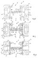
- the support 2 consists of at least two support parts 5, 6. These two support members 5, 6 are formed identically, as an injection molded part. They are made of aluminum or an aluminum alloy.
- the support part 5 has a first U-shaped receptacle 7 and the second support part 6 has a second U-shaped receptacle 8.
- Each receptacle 7 or 8 has two parallel legs 9, 10 and a leg 11 connecting these legs 9, 10.
- the two support members 5 and 6 are in the region of the two webs 11 to each other and are connected to each other.
- the arrangement of the two side parts 5 and 6 forms a substantially H-shaped cross-section.
- the two support members 5 and 6 are welded by means extending over the length of the support 2 extending welds 12.
- the respective receptacle 7 or 8 has in the region of the end, which faces away from the other receptacle, a short, parallel to the web 11 directed approach 13.
- This projection 13 is also U-shaped and serves to receive a sealing element 14 with lip 15.
- the sealing element 14 extends over the height of the support 2 and seals against the dam 2 inserted into the support 2 from.
- the further sealing element 14 is provided to ensure a universal installation of the flood protection wall 1, thus regardless of which side of the support 2 is opposite to the expected flood.
- the supports 2 may have different distances from one another and, consequently, the dam beams 3 to be inserted into adjacent supports 2 have an adapted length.
- dam beams with a respective length of 500 mm to 7 000 mm are conceivable.
- the outer contour of the respective dam beam 3 is rectangular; the dam beams 3 are stacked upright.
- the two support parts 5 and 6 are welded together not only in the region of the weld seams 12 over partial regions of the height of the support 2, but rather that the respective support part 5 or 6 has an undercut groove 16 in the region of the legs 9 thereof extends over the height of the support member 5 and 6 respectively.
- the respective support part 5 or 6 has an undercut groove 16 in the region of the legs 9 thereof extends over the height of the support member 5 and 6 respectively.
- the respective reinforcing member 17 has correspondingly two T-shaped projections 18 which are inserted into the two grooves 16.
- the respective reinforcing parts 17, wherein four reinforcing parts 17 are illustrated on each of the opposite sides of the support 2, are positioned substantially uniformly distributed over the height of the support 2 and welded in horizontally aligned position to the respective support part 5 and 6, respectively.
- the welding takes place in the circumferential region of the reinforcing member 17 with the associated support member 5 and 6, thus by means of a circumferential weld between reinforcing member 17 and support member 5 and 6.
- the second of the reinforcing members 17, viewed from above, in this case has a recess 19, so that this reinforcing member 17 has the function of a handle for supporting the support 2.
- the reinforcing parts 17 are formed substantially trapezoidal. The long side of the trapezoid is facing the side part 5 and 6 respectively. There the welding takes place.
- the support 2 in the lower region, to the two support members 5 and 6 on opposite sides of the support 2 welded base plates 20 and vertically extending reinforcing plates 21. These are also welded to the support parts 5 and 6 respectively.
- the support 2 thus presents itself as a rigid structure, the output of the production of the support 2 forming the two identical support elements 5 and 6 in the form of an extruded profile, which are welded together and subsequently further reinforcements are welded to the support parts 5 and 6, in FIG Type of reinforcing parts 17, 21 and bottom plates 20.
- the bottom plates 20 are provided with holes, for connection to bolts, which are embedded in a foundation. As a result, the support 2 can be firmly connected to the foundation.
- the respective support member 5 and 6 is also provided in the region of the web 11 with two grooves 23 and between them with two undercut grooves 24.
- the two adjacent grooves 23 of the two support parts 5, 6 form an overall groove with a rectangular cross section.
- a rectangular rod 30 can be inserted from above, which serves the purpose of increasing the shear strength of the structure of the support part 5 and the support part 6.
- shear forces acting on legs 9 or 10 of one support part 5, depending on the direction of pressure of the flood can be transmitted via the rod 30 into the other support part 6 via the rod 30 inserted into the respective arrangement of the grooves 23.
- the respective adjacent undercut grooves 24 form an H-shaped cross-section.
- a cross-sectionally H-shaped rod 31 can be used.
- This rod 31 contributes significantly to the flexural rigidity of the support 2 and it may be such Rod 31 also tensile forces that are effective under the action of the flood in the longitudinal direction of the dam bars 3 between the two support members 5, 6 record.
- compounds may well be designed as adhesive bonds.
- the two support parts 5 and 6 may be glued together in the region of the webs 11.
- the Fig. 8 to 10 show an alternative design of the support 2.
- This reinforcing plate 27 has a constant thickness.
- the support 2 thus has a third support part which is arranged between the two other support parts 5, 6.
- the support members 5 and 6 on the mutually facing sides with this third support part - reinforcing plate 27 - connected.
- the reinforcing plate has a constant thickness and is connected in the region of each circumferential weld 28 with the associated support member 5 and 6 in the outer transition of leg 9 and web 11 and leg 10 and web 11.
- the reinforcing plate 27 extends over the entire height of the support members 5 and 6 and over the perpendicular to this extending plate-shaped diverse reinforcing members 17 addition. Below the reinforcing plate 27 closes in the region of the opposite ends approximately with the bottom plate 20 in the region of its outer contour.
- the third embodiment according to the Fig. 11 differs from the one after the Fig. 8 to 10 essentially in that no reinforcing plate 27 is arranged between the two support parts 5 and 6, but a box-shaped reinforcing part 29.
- the reinforcing member 29 formed as a hollow body increases the bending, buckling and torsional rigidity the support 2 considerably, so that this embodiment is suitable for extreme storage heights and / or particularly long dam bars 3.
- On opposite sides of the reinforcing member 27 is provided with the grooves 23 and 25.
- the support members 5 and 6 serve to receive the reinforcing members 17, floor panels 20 and reinforcing members 21.
Landscapes
- Engineering & Computer Science (AREA)
- General Engineering & Computer Science (AREA)
- Structural Engineering (AREA)
- Civil Engineering (AREA)
- Architecture (AREA)
- Environmental & Geological Engineering (AREA)
- Mechanical Engineering (AREA)
- Ocean & Marine Engineering (AREA)
- Business, Economics & Management (AREA)
- Emergency Management (AREA)
- Buildings Adapted To Withstand Abnormal External Influences (AREA)
- Body Structure For Vehicles (AREA)
Priority Applications (1)
| Application Number | Priority Date | Filing Date | Title |
|---|---|---|---|
| EP16171717.8A EP3249103B1 (fr) | 2016-05-27 | 2016-05-27 | Support pour un mur de protection contre l'inondation |
Applications Claiming Priority (1)
| Application Number | Priority Date | Filing Date | Title |
|---|---|---|---|
| EP16171717.8A EP3249103B1 (fr) | 2016-05-27 | 2016-05-27 | Support pour un mur de protection contre l'inondation |
Publications (2)
| Publication Number | Publication Date |
|---|---|
| EP3249103A1 true EP3249103A1 (fr) | 2017-11-29 |
| EP3249103B1 EP3249103B1 (fr) | 2020-08-26 |
Family
ID=56098030
Family Applications (1)
| Application Number | Title | Priority Date | Filing Date |
|---|---|---|---|
| EP16171717.8A Not-in-force EP3249103B1 (fr) | 2016-05-27 | 2016-05-27 | Support pour un mur de protection contre l'inondation |
Country Status (1)
| Country | Link |
|---|---|
| EP (1) | EP3249103B1 (fr) |
Citations (6)
| Publication number | Priority date | Publication date | Assignee | Title |
|---|---|---|---|---|
| DE29916656U1 (de) | 1999-07-30 | 2000-01-05 | Mühle, Manfred, 32278 Kirchlengern | Transportable Hochwasserschutzwand |
| FR2871494A1 (fr) * | 2004-06-09 | 2005-12-16 | Debarge Bois Sarl | Poteau de cloture forme par assemblage de deux demi-poteaux avec meplats en aluminium |
| AT505404A4 (de) * | 2007-10-08 | 2009-01-15 | Neuman Aluminium Strangpresswe | Hochwasserschutzeinrichtung |
| EP2060680A1 (fr) | 2007-10-17 | 2009-05-20 | Claudia Kusch | Support pour un mur de protection contre l'inondation |
| GB2500099A (en) * | 2012-02-20 | 2013-09-11 | Nicholas Holden Pty Ltd | Post with panel receiving opening |
| DE102014101780A1 (de) * | 2014-02-13 | 2015-08-13 | Mathias Groß | Stützpfosten für eine Wand |
-
2016
- 2016-05-27 EP EP16171717.8A patent/EP3249103B1/fr not_active Not-in-force
Patent Citations (6)
| Publication number | Priority date | Publication date | Assignee | Title |
|---|---|---|---|---|
| DE29916656U1 (de) | 1999-07-30 | 2000-01-05 | Mühle, Manfred, 32278 Kirchlengern | Transportable Hochwasserschutzwand |
| FR2871494A1 (fr) * | 2004-06-09 | 2005-12-16 | Debarge Bois Sarl | Poteau de cloture forme par assemblage de deux demi-poteaux avec meplats en aluminium |
| AT505404A4 (de) * | 2007-10-08 | 2009-01-15 | Neuman Aluminium Strangpresswe | Hochwasserschutzeinrichtung |
| EP2060680A1 (fr) | 2007-10-17 | 2009-05-20 | Claudia Kusch | Support pour un mur de protection contre l'inondation |
| GB2500099A (en) * | 2012-02-20 | 2013-09-11 | Nicholas Holden Pty Ltd | Post with panel receiving opening |
| DE102014101780A1 (de) * | 2014-02-13 | 2015-08-13 | Mathias Groß | Stützpfosten für eine Wand |
Also Published As
| Publication number | Publication date |
|---|---|
| EP3249103B1 (fr) | 2020-08-26 |
Similar Documents
| Publication | Publication Date | Title |
|---|---|---|
| DE19720016C2 (de) | Vorgehängte Fassadenkonstruktion | |
| DE69004325T2 (de) | Verbaukorbschalung. | |
| EP2010023B1 (fr) | Planchette d'etagere | |
| DE1903129B2 (de) | Vorrichtung zum Anschließen eines Trägers an eine Betonstütze | |
| DE2128609A1 (de) | Verstärkte Schalungsplatte fur Be tonschalungen | |
| DE102009025310A1 (de) | Stoßfängersystem für ein Kraftfahrzeug | |
| EP2060680A1 (fr) | Support pour un mur de protection contre l'inondation | |
| DE102019125318A1 (de) | Spielfeldbegrenzung für ein Kleinspielfeld | |
| DE2206973A1 (de) | Raeumliches bauelement zur bildung von trag- und stuetzwerken aller art | |
| EP0484741B1 (fr) | Noeud pour treillis | |
| EP0563707B1 (fr) | Panneau de coffrage | |
| DE2100874A1 (de) | Trägerrost | |
| EP1270833A2 (fr) | Elément de construction pour l'isolation thermique | |
| DE19820030A1 (de) | Fassadenprofil | |
| EP1860246B1 (fr) | Elément de construction pour isolation thermique | |
| EP3249103B1 (fr) | Support pour un mur de protection contre l'inondation | |
| EP2428626A2 (fr) | Paroi pour la séparation de produits en vrac | |
| DE29924191U1 (de) | Regal | |
| DE2319190A1 (de) | Vorrichtung zur herstellung von ausnehmungen in gussbeton | |
| DE102018112634A1 (de) | Fugenprofil | |
| EP4183525B1 (fr) | Table pour une machine à banc plat et procédé de fabrication d'une table pour une machine à banc plat | |
| AT501334B1 (de) | Rahmenkonstruktion | |
| EP3753857A1 (fr) | Élément de paroi d'un cadre de rehausse de palette et cadre de rehausse de palette | |
| DE102007047439A1 (de) | Schalungsanrodnung für den Freivorbau von Brücken | |
| AT403184B (de) | Schalungstafel |
Legal Events
| Date | Code | Title | Description |
|---|---|---|---|
| PUAI | Public reference made under article 153(3) epc to a published international application that has entered the european phase |
Free format text: ORIGINAL CODE: 0009012 |
|
| STAA | Information on the status of an ep patent application or granted ep patent |
Free format text: STATUS: THE APPLICATION HAS BEEN PUBLISHED |
|
| AK | Designated contracting states |
Kind code of ref document: A1 Designated state(s): AL AT BE BG CH CY CZ DE DK EE ES FI FR GB GR HR HU IE IS IT LI LT LU LV MC MK MT NL NO PL PT RO RS SE SI SK SM TR |
|
| AX | Request for extension of the european patent |
Extension state: BA ME |
|
| STAA | Information on the status of an ep patent application or granted ep patent |
Free format text: STATUS: REQUEST FOR EXAMINATION WAS MADE |
|
| 17P | Request for examination filed |
Effective date: 20180523 |
|
| RBV | Designated contracting states (corrected) |
Designated state(s): AL AT BE BG CH CY CZ DE DK EE ES FI FR GB GR HR HU IE IS IT LI LT LU LV MC MK MT NL NO PL PT RO RS SE SI SK SM TR |
|
| RAP1 | Party data changed (applicant data changed or rights of an application transferred) |
Owner name: STEINHARDT GMBH |
|
| RIN1 | Information on inventor provided before grant (corrected) |
Inventor name: STEINHARDT, JOERG-MICHAEL |
|
| GRAP | Despatch of communication of intention to grant a patent |
Free format text: ORIGINAL CODE: EPIDOSNIGR1 |
|
| STAA | Information on the status of an ep patent application or granted ep patent |
Free format text: STATUS: GRANT OF PATENT IS INTENDED |
|
| RIC1 | Information provided on ipc code assigned before grant |
Ipc: E02B 3/10 20060101AFI20200318BHEP Ipc: E04H 17/20 20060101ALN20200318BHEP Ipc: E04H 9/14 20060101ALN20200318BHEP Ipc: E02B 7/22 20060101ALI20200318BHEP Ipc: E02B 7/54 20060101ALN20200318BHEP |
|
| INTG | Intention to grant announced |
Effective date: 20200406 |
|
| GRAS | Grant fee paid |
Free format text: ORIGINAL CODE: EPIDOSNIGR3 |
|
| GRAA | (expected) grant |
Free format text: ORIGINAL CODE: 0009210 |
|
| STAA | Information on the status of an ep patent application or granted ep patent |
Free format text: STATUS: THE PATENT HAS BEEN GRANTED |
|
| AK | Designated contracting states |
Kind code of ref document: B1 Designated state(s): AL AT BE BG CH CY CZ DE DK EE ES FI FR GB GR HR HU IE IS IT LI LT LU LV MC MK MT NL NO PL PT RO RS SE SI SK SM TR |
|
| REG | Reference to a national code |
Ref country code: GB Ref legal event code: FG4D Free format text: NOT ENGLISH |
|
| REG | Reference to a national code |
Ref country code: CH Ref legal event code: EP |
|
| REG | Reference to a national code |
Ref country code: AT Ref legal event code: REF Ref document number: 1306481 Country of ref document: AT Kind code of ref document: T Effective date: 20200915 |
|
| REG | Reference to a national code |
Ref country code: IE Ref legal event code: FG4D Free format text: LANGUAGE OF EP DOCUMENT: GERMAN |
|
| REG | Reference to a national code |
Ref country code: DE Ref legal event code: R096 Ref document number: 502016010928 Country of ref document: DE |
|
| REG | Reference to a national code |
Ref country code: LT Ref legal event code: MG4D |
|
| PG25 | Lapsed in a contracting state [announced via postgrant information from national office to epo] |
Ref country code: FI Free format text: LAPSE BECAUSE OF FAILURE TO SUBMIT A TRANSLATION OF THE DESCRIPTION OR TO PAY THE FEE WITHIN THE PRESCRIBED TIME-LIMIT Effective date: 20200826 Ref country code: SE Free format text: LAPSE BECAUSE OF FAILURE TO SUBMIT A TRANSLATION OF THE DESCRIPTION OR TO PAY THE FEE WITHIN THE PRESCRIBED TIME-LIMIT Effective date: 20200826 Ref country code: NO Free format text: LAPSE BECAUSE OF FAILURE TO SUBMIT A TRANSLATION OF THE DESCRIPTION OR TO PAY THE FEE WITHIN THE PRESCRIBED TIME-LIMIT Effective date: 20201126 Ref country code: GR Free format text: LAPSE BECAUSE OF FAILURE TO SUBMIT A TRANSLATION OF THE DESCRIPTION OR TO PAY THE FEE WITHIN THE PRESCRIBED TIME-LIMIT Effective date: 20201127 Ref country code: PT Free format text: LAPSE BECAUSE OF FAILURE TO SUBMIT A TRANSLATION OF THE DESCRIPTION OR TO PAY THE FEE WITHIN THE PRESCRIBED TIME-LIMIT Effective date: 20201228 Ref country code: HR Free format text: LAPSE BECAUSE OF FAILURE TO SUBMIT A TRANSLATION OF THE DESCRIPTION OR TO PAY THE FEE WITHIN THE PRESCRIBED TIME-LIMIT Effective date: 20200826 Ref country code: BG Free format text: LAPSE BECAUSE OF FAILURE TO SUBMIT A TRANSLATION OF THE DESCRIPTION OR TO PAY THE FEE WITHIN THE PRESCRIBED TIME-LIMIT Effective date: 20201126 Ref country code: LT Free format text: LAPSE BECAUSE OF FAILURE TO SUBMIT A TRANSLATION OF THE DESCRIPTION OR TO PAY THE FEE WITHIN THE PRESCRIBED TIME-LIMIT Effective date: 20200826 |
|
| REG | Reference to a national code |
Ref country code: NL Ref legal event code: MP Effective date: 20200826 |
|
| PG25 | Lapsed in a contracting state [announced via postgrant information from national office to epo] |
Ref country code: NL Free format text: LAPSE BECAUSE OF FAILURE TO SUBMIT A TRANSLATION OF THE DESCRIPTION OR TO PAY THE FEE WITHIN THE PRESCRIBED TIME-LIMIT Effective date: 20200826 Ref country code: LV Free format text: LAPSE BECAUSE OF FAILURE TO SUBMIT A TRANSLATION OF THE DESCRIPTION OR TO PAY THE FEE WITHIN THE PRESCRIBED TIME-LIMIT Effective date: 20200826 Ref country code: PL Free format text: LAPSE BECAUSE OF FAILURE TO SUBMIT A TRANSLATION OF THE DESCRIPTION OR TO PAY THE FEE WITHIN THE PRESCRIBED TIME-LIMIT Effective date: 20200826 Ref country code: RS Free format text: LAPSE BECAUSE OF FAILURE TO SUBMIT A TRANSLATION OF THE DESCRIPTION OR TO PAY THE FEE WITHIN THE PRESCRIBED TIME-LIMIT Effective date: 20200826 Ref country code: IS Free format text: LAPSE BECAUSE OF FAILURE TO SUBMIT A TRANSLATION OF THE DESCRIPTION OR TO PAY THE FEE WITHIN THE PRESCRIBED TIME-LIMIT Effective date: 20201226 |
|
| PG25 | Lapsed in a contracting state [announced via postgrant information from national office to epo] |
Ref country code: EE Free format text: LAPSE BECAUSE OF FAILURE TO SUBMIT A TRANSLATION OF THE DESCRIPTION OR TO PAY THE FEE WITHIN THE PRESCRIBED TIME-LIMIT Effective date: 20200826 Ref country code: SM Free format text: LAPSE BECAUSE OF FAILURE TO SUBMIT A TRANSLATION OF THE DESCRIPTION OR TO PAY THE FEE WITHIN THE PRESCRIBED TIME-LIMIT Effective date: 20200826 Ref country code: RO Free format text: LAPSE BECAUSE OF FAILURE TO SUBMIT A TRANSLATION OF THE DESCRIPTION OR TO PAY THE FEE WITHIN THE PRESCRIBED TIME-LIMIT Effective date: 20200826 Ref country code: DK Free format text: LAPSE BECAUSE OF FAILURE TO SUBMIT A TRANSLATION OF THE DESCRIPTION OR TO PAY THE FEE WITHIN THE PRESCRIBED TIME-LIMIT Effective date: 20200826 Ref country code: CZ Free format text: LAPSE BECAUSE OF FAILURE TO SUBMIT A TRANSLATION OF THE DESCRIPTION OR TO PAY THE FEE WITHIN THE PRESCRIBED TIME-LIMIT Effective date: 20200826 |
|
| REG | Reference to a national code |
Ref country code: DE Ref legal event code: R097 Ref document number: 502016010928 Country of ref document: DE |
|
| PG25 | Lapsed in a contracting state [announced via postgrant information from national office to epo] |
Ref country code: ES Free format text: LAPSE BECAUSE OF FAILURE TO SUBMIT A TRANSLATION OF THE DESCRIPTION OR TO PAY THE FEE WITHIN THE PRESCRIBED TIME-LIMIT Effective date: 20200826 Ref country code: AL Free format text: LAPSE BECAUSE OF FAILURE TO SUBMIT A TRANSLATION OF THE DESCRIPTION OR TO PAY THE FEE WITHIN THE PRESCRIBED TIME-LIMIT Effective date: 20200826 |
|
| PG25 | Lapsed in a contracting state [announced via postgrant information from national office to epo] |
Ref country code: SK Free format text: LAPSE BECAUSE OF FAILURE TO SUBMIT A TRANSLATION OF THE DESCRIPTION OR TO PAY THE FEE WITHIN THE PRESCRIBED TIME-LIMIT Effective date: 20200826 |
|
| PLBE | No opposition filed within time limit |
Free format text: ORIGINAL CODE: 0009261 |
|
| STAA | Information on the status of an ep patent application or granted ep patent |
Free format text: STATUS: NO OPPOSITION FILED WITHIN TIME LIMIT |
|
| PG25 | Lapsed in a contracting state [announced via postgrant information from national office to epo] |
Ref country code: IT Free format text: LAPSE BECAUSE OF FAILURE TO SUBMIT A TRANSLATION OF THE DESCRIPTION OR TO PAY THE FEE WITHIN THE PRESCRIBED TIME-LIMIT Effective date: 20200826 |
|
| 26N | No opposition filed |
Effective date: 20210527 |
|
| PG25 | Lapsed in a contracting state [announced via postgrant information from national office to epo] |
Ref country code: SI Free format text: LAPSE BECAUSE OF FAILURE TO SUBMIT A TRANSLATION OF THE DESCRIPTION OR TO PAY THE FEE WITHIN THE PRESCRIBED TIME-LIMIT Effective date: 20200826 |
|
| REG | Reference to a national code |
Ref country code: DE Ref legal event code: R119 Ref document number: 502016010928 Country of ref document: DE |
|
| REG | Reference to a national code |
Ref country code: CH Ref legal event code: PL |
|
| GBPC | Gb: european patent ceased through non-payment of renewal fee |
Effective date: 20210527 |
|
| PG25 | Lapsed in a contracting state [announced via postgrant information from national office to epo] |
Ref country code: MC Free format text: LAPSE BECAUSE OF FAILURE TO SUBMIT A TRANSLATION OF THE DESCRIPTION OR TO PAY THE FEE WITHIN THE PRESCRIBED TIME-LIMIT Effective date: 20200826 Ref country code: LU Free format text: LAPSE BECAUSE OF NON-PAYMENT OF DUE FEES Effective date: 20210527 Ref country code: LI Free format text: LAPSE BECAUSE OF NON-PAYMENT OF DUE FEES Effective date: 20210531 Ref country code: CH Free format text: LAPSE BECAUSE OF NON-PAYMENT OF DUE FEES Effective date: 20210531 |
|
| REG | Reference to a national code |
Ref country code: BE Ref legal event code: MM Effective date: 20210531 |
|
| PG25 | Lapsed in a contracting state [announced via postgrant information from national office to epo] |
Ref country code: IE Free format text: LAPSE BECAUSE OF NON-PAYMENT OF DUE FEES Effective date: 20210527 Ref country code: GB Free format text: LAPSE BECAUSE OF NON-PAYMENT OF DUE FEES Effective date: 20210527 Ref country code: DE Free format text: LAPSE BECAUSE OF NON-PAYMENT OF DUE FEES Effective date: 20211201 |
|
| PG25 | Lapsed in a contracting state [announced via postgrant information from national office to epo] |
Ref country code: FR Free format text: LAPSE BECAUSE OF NON-PAYMENT OF DUE FEES Effective date: 20210531 |
|
| REG | Reference to a national code |
Ref country code: AT Ref legal event code: MM01 Ref document number: 1306481 Country of ref document: AT Kind code of ref document: T Effective date: 20210527 |
|
| PG25 | Lapsed in a contracting state [announced via postgrant information from national office to epo] |
Ref country code: BE Free format text: LAPSE BECAUSE OF NON-PAYMENT OF DUE FEES Effective date: 20210531 |
|
| PG25 | Lapsed in a contracting state [announced via postgrant information from national office to epo] |
Ref country code: AT Free format text: LAPSE BECAUSE OF NON-PAYMENT OF DUE FEES Effective date: 20210527 |
|
| PG25 | Lapsed in a contracting state [announced via postgrant information from national office to epo] |
Ref country code: HU Free format text: LAPSE BECAUSE OF FAILURE TO SUBMIT A TRANSLATION OF THE DESCRIPTION OR TO PAY THE FEE WITHIN THE PRESCRIBED TIME-LIMIT; INVALID AB INITIO Effective date: 20160527 |
|
| PG25 | Lapsed in a contracting state [announced via postgrant information from national office to epo] |
Ref country code: CY Free format text: LAPSE BECAUSE OF FAILURE TO SUBMIT A TRANSLATION OF THE DESCRIPTION OR TO PAY THE FEE WITHIN THE PRESCRIBED TIME-LIMIT Effective date: 20200826 |
|
| PG25 | Lapsed in a contracting state [announced via postgrant information from national office to epo] |
Ref country code: MK Free format text: LAPSE BECAUSE OF FAILURE TO SUBMIT A TRANSLATION OF THE DESCRIPTION OR TO PAY THE FEE WITHIN THE PRESCRIBED TIME-LIMIT Effective date: 20200826 |
|
| PG25 | Lapsed in a contracting state [announced via postgrant information from national office to epo] |
Ref country code: MT Free format text: LAPSE BECAUSE OF FAILURE TO SUBMIT A TRANSLATION OF THE DESCRIPTION OR TO PAY THE FEE WITHIN THE PRESCRIBED TIME-LIMIT Effective date: 20200826 |
|
| PG25 | Lapsed in a contracting state [announced via postgrant information from national office to epo] |
Ref country code: TR Free format text: LAPSE BECAUSE OF FAILURE TO SUBMIT A TRANSLATION OF THE DESCRIPTION OR TO PAY THE FEE WITHIN THE PRESCRIBED TIME-LIMIT Effective date: 20200826 |