EP2428626A2 - Paroi pour la séparation de produits en vrac - Google Patents
Paroi pour la séparation de produits en vrac Download PDFInfo
- Publication number
- EP2428626A2 EP2428626A2 EP11007171A EP11007171A EP2428626A2 EP 2428626 A2 EP2428626 A2 EP 2428626A2 EP 11007171 A EP11007171 A EP 11007171A EP 11007171 A EP11007171 A EP 11007171A EP 2428626 A2 EP2428626 A2 EP 2428626A2
- Authority
- EP
- European Patent Office
- Prior art keywords
- holding part
- partition wall
- shelf according
- substructure
- wall
- Prior art date
- Legal status (The legal status is an assumption and is not a legal conclusion. Google has not performed a legal analysis and makes no representation as to the accuracy of the status listed.)
- Granted
Links
Images



Classifications
-
- E—FIXED CONSTRUCTIONS
- E04—BUILDING
- E04H—BUILDINGS OR LIKE STRUCTURES FOR PARTICULAR PURPOSES; SWIMMING OR SPLASH BATHS OR POOLS; MASTS; FENCING; TENTS OR CANOPIES, IN GENERAL
- E04H7/00—Construction or assembling of bulk storage containers employing civil engineering techniques in situ or off the site
- E04H7/22—Containers for fluent solids, e.g. silos, bunkers; Supports therefor
- E04H7/24—Constructions, with or without perforated walls, depending on the use of specified materials
- E04H7/30—Constructions, with or without perforated walls, depending on the use of specified materials mainly of metal
-
- E—FIXED CONSTRUCTIONS
- E04—BUILDING
- E04H—BUILDINGS OR LIKE STRUCTURES FOR PARTICULAR PURPOSES; SWIMMING OR SPLASH BATHS OR POOLS; MASTS; FENCING; TENTS OR CANOPIES, IN GENERAL
- E04H7/00—Construction or assembling of bulk storage containers employing civil engineering techniques in situ or off the site
- E04H7/22—Containers for fluent solids, e.g. silos, bunkers; Supports therefor
- E04H2007/225—Silos with retaining wall type wall elements, e.g. trench silos
Definitions
- the invention relates to a partition wall for the separation of bulk materials, with a bottom plate and side walls, which are connected to one another at least partially fillable with a filling cavity, and with at least one holding part, which is arranged in the region of the upper edge of the partition wall and means the forces acting on a located on the upper edge of the partition wall roof construction forces are absorbed or derivable.
- partitions are often put together to form partition assemblies, which are provided by these partition assemblies various chambers formed by the partition walls, in which bulk materials of different types can be stored.
- roof structures are arranged on the shelving arrangements to odg the stored bulk goods against the weather. to protect.
- the invention has for its object to improve the initially described partition such that without consuming structural measures that can be absorbed by the partition walls, can be considerably increased by the roof structures on the partitions transmitted forces.
- each arranged in the region of the upper edge of the partition wall holding part is associated with a substructure, by means of the transmitted from the roof structure to the holding part forces are forwarded.
- the partition now serves the partition in its entirety, i. including its bottom plate, etc., as Kraftability- or Kraftableitungssch.
- the entire weight of the partition is available from the outset to compensate any forces acting on the roof construction.
- the substructure extends from the holding part to a preferably end-side side wall of the partition wall.
- the forces acting on the holding part can be forwarded by means of the substructure and the side wall to the bottom plate.
- the partition wall is provided with a cover plate which forms the upper end of the partition and at least that a holding part is arranged, the partition in the head area is additionally stabilized by acting as a stiffening cover plate. On the cover plate holding parts can then be mounted in a simple manner.
- the substructure of the at least one holding part is advantageously formed of carriers that form a supporting structure.
- the substructure of the at least one holding part can be formed from horizontally and vertically arranged carriers, which in turn configure a ladder-type supporting structure.
- a resilient attachment of the holding part on the side walls and possibly on the bottom plate of the partition wall is achieved by simple means.
- the substructure of the at least one holding part of vertically and obliquely arranged carriers which form a truss-like structure.
- this truss-like design of the substructure can offer advantages.
- the substructure is firmly connected to the bottom plate and with the running in the longitudinal direction of the partition longitudinal side walls, preferably welded, is.
- a connection between the substructure and the end walls of the partition can be created.
- the substructure of the at least one holding part can be formed with a comparatively small technical and constructional outlay from flat iron and / or from angle iron.
- the at least one holding part of the partition can have a T-section or a double-T section.
- the holding parts of the partition wall are designed as consoles with which the roof construction is connectable.
- connection between the roof structure and the brackets of the partition can be advantageously designed as a screw connection.
- the width of the console suitably corresponds to the inner width of the partition in the region of its upper edge, so that a simple welding of the console in the partition wall is possible.
- the thickness of the partition wall between the bottom plate and its upper edge in the upward direction preferably decreases gradually and evenly. As a result, the surface pressure exerted by the partition can be significantly reduced without the weight of the partition would have to be reduced.
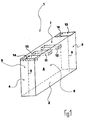
- FIG. 1 An in FIG. 1 according to one embodiment shown in principle partition wall 1 according to the invention is usually part of an arrangement of a plurality of such partitions 1.
- Such partitions 1 or partition arrangements come in particular in the storage of bulk materials, namely where bulk goods must be stored separately and / or sorted.
- the areas of application include, in particular, recycling and disposal companies, composting plants, container services, civil engineering and green space offices of municipalities, ports, metallurgical plants, road construction and civil engineering companies, the building materials trade, city cleaning and agriculture and horticulture.
- partition wall 1 has a bottom plate 2, two Stirn interactwandept 3, 4 and two Lijns109wandept 5, 6.
- the bottom plate 2 and the four side walls 3, 4, 5, 6 include a cavity 8 a.
- This cavity can be completely or partially filled with a filling material.
- an opening is provided at a suitable location through which the cavity 8 can be filled.
- the cavity 8 can be filled with a suitable filling material 9, wherein also in terms of the desired or required degree of filling each desired profile of requirements can be met arbitrarily. The higher the degree of filling of the cavity 8 with filling, the greater the weight of the partition wall 1 and the steadier it is.
- the partition wall 1 may have a cover plate 7, as shown in FIG FIG. 1 is indicated by the corresponding reference numeral.
- brackets 11, 12 are provided which penetrate the partition wall 1.
- the two brackets 11, 12 are spaced from each other so that a conventional, in FIG. 1 not shown Forklift can be used to transport the partition wall 1 from one place to another.
- the upper edge or possibly the cover plate 7 of the partition wall 1 is designed so that suitable roof elements on the plurality of partitions 1 having partition wall arrangement can be placed, with the result that the bulk material arranged under these roof elements against precipitation and is stored protected from above.
- FIG. 1 an embodiment of the partition wall 1 according to the invention is shown, in which in the region of the upper edge or possibly the cover plate 7 of the partition 1, two connection plates or holding parts 13 are provided, which serve to connect a roof structure.
- the holding parts 13 are arranged in the illustrated embodiment, at the ends of the partition wall 1 and provided with holes 14, by means of which a roof construction on the holding parts 13 on the partition wall 1 can be fastened.
- the holding parts 13 are welded to the side walls 4, 5, 6 and 3, 5, 6 and may be formed of steel.
- a suitable connection for example a welded joint, with the cover plate 7 is conceivable.
- the two holding parts 13 are each provided with a substructure 9, by means of which each holding part 13 is fixedly connected to the bottom plate 2 of the partition wall 1. Forces exerted on the holding parts 13, which are transmitted from the roof structure to the holding parts 13, are thus forwarded and received by means of the respective substructure 9 to the partition wall construction.
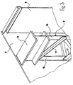
- the partition wall 1 shows that the holding part 13 is formed as a console 13 by a T-beam.
- the T-beam is welded to the Lijnswoowandonne 5, 6, wherein from FIG. 2 only the weld on the rear longitudinal side wall 5 emerges.
- the holding part or the console 13 is welded on its underside with vertically arranged carriers 15 of the substructure 9. These vertically arranged carrier 15 extend from the underside of the holding part or the console 13 to in FIG. 2 Bottom plate 2, not shown, of the partition wall 1, with which they are also welded.
- the vertically arranged carriers 15 are welded to the inner sides of the longitudinal side walls 5, 6 at their edges assigned to the longitudinal side walls 5, 6. Again, only the welding with the in FIG. 2 rear Lhacksdorfwandung 5 shown.
- the substructure 9 of the holding parts provided only up to in the partition wall 1 Horizontal struts and not to the bottom plate 2 extends.
- a perpendicular to this and thus horizontally arranged support 16 which is welded at its two ends to the vertically arranged supports 15.
- a corresponding number of horizontally arranged support 16 is provided.
- the substructure 9 is in the case of in FIG. 2 thus shown embodiment configured as a ladder-like structure. Basically, it is possible with a lower requirement profile of the partition wall 1 to dispense with the horizontally arranged carrier 16.
- FIG. 2 shown embodiment of the substructure 9 is provided in the longitudinal direction of the partition wall 1 extending carrier 10, by means of which the vertically arranged carrier 15 of the substructure 9 are connected to the end side walls 3, 4.
- the carrier 10 arranged on the inside of the rear longitudinal side wall 5 in the figure is shown. This is with both the vertically arranged carrier 15 and with the inside of in FIG. 2 shown Stirnjandung 3 welded.
- Another carrier 10 connects in the same way in FIG. 2 shown substructure 9 with the in FIG. 2 not shown Stirnatewandung 4 or one between the in FIG. 2 shown substructure 9 and this Stirnatewandung 4 arranged further substructure.
- the holding part 13 is formed as a double-T-carrier.
- two vertically arranged carrier 15 are also provided, which in the already with reference to FIG. 2 described manner with the bottom plate 2 or provided in the partition wall 1 horizontal struts and the Lijnsstenwandept 5, 6 of the partition wall 1 are welded.
- substructure 9 Between the two vertically arranged supports 15 of the FIG. 3 shown substructure 9 are arranged at an angle to the horizontal inclined support 17, which form a truss-like structure together with the vertically arranged supports 15. Also by means of the support structure designed in this way, forces acting on the holding part or on the bracket 13 via the roof construction can be uniformly discharged onto the movable wall 1 and correspondingly received there.
- the oblique beams 17 can, as in FIG. 3 is shown to be formed as an angle iron.
- the carriers 10, 15, 16 arranged in the vertical direction and in the horizontal direction are each configured as flat iron.
- the above-described partition can be installed without it being necessary to provide a foundation for this.
- the partition can be designed to have a trapezoidal cross-section, with the result that the bottom plate is much larger than the top edge and thus the one applied to the ground Surface pressure is considerably lower.
- the partition can thus serve as a bulkhead for bulk materials, and in the above embodiment, it is also support structure for a roof construction or roof elements.
- FIG. 4 an embodiment of a partition wall 1 is shown, in which the substructure in the form of two inclined support 9a, 9b extends from the holding part 13 to the provided in the region of the holding part 13 front side wall 4 of the partition wall 1. Due to the welding of the inclined support 9a, 9b also with the side walls 5 and 6 are on Holding part 13 attacking forces derived in the partition wall construction.
- FIG. 5 an embodiment of a holding part 13 is shown, which rests on the opposite side walls 4 of two adjacent partitions 1.
- the two end-side side walls 4, 4 of the two adjacent partitions 1, 1 then form the substructure for the holding part 13.
- the holding part 13 or the console rests quasi on two partitions, the two opposite end-side side walls 4, 4 of these two partitions. 1 , 1 can be used as a supporting structure for the console. This creates a kind of hollow profile as a structure by means of which torsional forces are absorbed.
Landscapes
- Engineering & Computer Science (AREA)
- Architecture (AREA)
- General Engineering & Computer Science (AREA)
- Civil Engineering (AREA)
- Structural Engineering (AREA)
- Devices Affording Protection Of Roads Or Walls For Sound Insulation (AREA)
- Body Structure For Vehicles (AREA)
- Joining Of Building Structures In Genera (AREA)
- Building Environments (AREA)
- Sewage (AREA)
- Residential Or Office Buildings (AREA)
Priority Applications (2)
| Application Number | Priority Date | Filing Date | Title |
|---|---|---|---|
| PL11007171T PL2428626T3 (pl) | 2010-09-11 | 2011-09-06 | Przegroda do rozdzielania materiałów sypkich |
| SI201131500T SI2428626T1 (en) | 2010-09-11 | 2011-09-06 | MAPPING STONE FOR MATCHING THE MATERIAL IN DIMENSION |
Applications Claiming Priority (1)
| Application Number | Priority Date | Filing Date | Title |
|---|---|---|---|
| DE202010012539U DE202010012539U1 (de) | 2010-09-11 | 2010-09-11 | Stellwand zur Separierung von Schüttgütern |
Publications (3)
| Publication Number | Publication Date |
|---|---|
| EP2428626A2 true EP2428626A2 (fr) | 2012-03-14 |
| EP2428626A3 EP2428626A3 (fr) | 2014-09-03 |
| EP2428626B1 EP2428626B1 (fr) | 2018-04-18 |
Family
ID=44533736
Family Applications (1)
| Application Number | Title | Priority Date | Filing Date |
|---|---|---|---|
| EP11007171.9A Active EP2428626B1 (fr) | 2010-09-11 | 2011-09-06 | Paroi pour la séparation de produits en vrac |
Country Status (8)
| Country | Link |
|---|---|
| EP (1) | EP2428626B1 (fr) |
| DE (1) | DE202010012539U1 (fr) |
| DK (1) | DK2428626T3 (fr) |
| ES (1) | ES2674903T3 (fr) |
| HU (1) | HUE038373T2 (fr) |
| PL (1) | PL2428626T3 (fr) |
| PT (1) | PT2428626T (fr) |
| SI (1) | SI2428626T1 (fr) |
Cited By (2)
| Publication number | Priority date | Publication date | Assignee | Title |
|---|---|---|---|---|
| CN104405165A (zh) * | 2014-11-25 | 2015-03-11 | 安徽省路桥工程集团有限责任公司 | 一种可重复利用的装配式拌合站储料仓隔墙及其施工方法 |
| CN106088755A (zh) * | 2016-07-12 | 2016-11-09 | 中冶京诚工程技术有限公司 | 一种预制装配式大型钢结构矩形仓及矩形群仓 |
Families Citing this family (1)
| Publication number | Priority date | Publication date | Assignee | Title |
|---|---|---|---|---|
| DE102024123917A1 (de) * | 2024-08-21 | 2026-02-26 | Lüra Holding GmbH | Stellwand zur Separierung von Schüttgütern |
Family Cites Families (6)
| Publication number | Priority date | Publication date | Assignee | Title |
|---|---|---|---|---|
| CA2106042C (fr) * | 1992-09-14 | 1997-01-07 | William G. Krage | Garde-fou routier |
| DE29504678U1 (de) * | 1995-03-18 | 1995-09-14 | Lüger, Stephan, 46242 Bottrop | Stellwandsystem für Schüttgüter |
| US6012872A (en) * | 1998-01-13 | 2000-01-11 | Tobor & Goldstein, L.L.P. | Flood control system |
| FR2865483B1 (fr) * | 2004-01-28 | 2006-03-03 | Michel Rene Marcel Caradot | Barrage anti inondations poids, lestable a l'eau, modulaire, creux, en pvc, en forme de trapeze rectangle |
| DE202006000880U1 (de) * | 2006-01-20 | 2006-09-07 | Lüger, Stephan | Stellwand zur Separierung von Schüttgütern |
| US7814714B2 (en) * | 2008-01-30 | 2010-10-19 | Cornbelt Fabric Structures, Llc | Apparatus and system to increase capacity of granular material storage structures |
-
2010
- 2010-09-11 DE DE202010012539U patent/DE202010012539U1/de not_active Expired - Lifetime
-
2011
- 2011-09-06 DK DK11007171.9T patent/DK2428626T3/en active
- 2011-09-06 EP EP11007171.9A patent/EP2428626B1/fr active Active
- 2011-09-06 SI SI201131500T patent/SI2428626T1/en unknown
- 2011-09-06 HU HUE11007171A patent/HUE038373T2/hu unknown
- 2011-09-06 PL PL11007171T patent/PL2428626T3/pl unknown
- 2011-09-06 ES ES11007171.9T patent/ES2674903T3/es active Active
- 2011-09-06 PT PT110071719T patent/PT2428626T/pt unknown
Non-Patent Citations (1)
| Title |
|---|
| None |
Cited By (3)
| Publication number | Priority date | Publication date | Assignee | Title |
|---|---|---|---|---|
| CN104405165A (zh) * | 2014-11-25 | 2015-03-11 | 安徽省路桥工程集团有限责任公司 | 一种可重复利用的装配式拌合站储料仓隔墙及其施工方法 |
| CN104405165B (zh) * | 2014-11-25 | 2016-09-14 | 安徽省路桥工程集团有限责任公司 | 一种可重复利用的装配式拌合站储料仓隔墙及其施工方法 |
| CN106088755A (zh) * | 2016-07-12 | 2016-11-09 | 中冶京诚工程技术有限公司 | 一种预制装配式大型钢结构矩形仓及矩形群仓 |
Also Published As
| Publication number | Publication date |
|---|---|
| EP2428626B1 (fr) | 2018-04-18 |
| ES2674903T3 (es) | 2018-07-04 |
| PT2428626T (pt) | 2018-07-04 |
| PL2428626T3 (pl) | 2018-11-30 |
| HUE038373T2 (hu) | 2018-10-29 |
| DK2428626T3 (en) | 2018-07-30 |
| EP2428626A3 (fr) | 2014-09-03 |
| DE202010012539U1 (de) | 2011-12-13 |
| SI2428626T1 (en) | 2018-08-31 |
Similar Documents
| Publication | Publication Date | Title |
|---|---|---|
| EP2647764B1 (fr) | Pièce de transition destinée à relier un pied de tour ou de mât à l'extrémité supérieure d'une structure de fondation en treillis dans la zone en mer | |
| DE102018007204B3 (de) | Schüttgutcontainer | |
| EP2623435B1 (fr) | Conteneur palette empilable | |
| DE2908818A1 (de) | Abbaubare barriere | |
| DE202008011835U1 (de) | Stütze für Flüssigkeitsschutzwand | |
| EP2428626B1 (fr) | Paroi pour la séparation de produits en vrac | |
| DE102019125318A1 (de) | Spielfeldbegrenzung für ein Kleinspielfeld | |
| EP3578439A1 (fr) | Châssis de construction légère | |
| EP2126218B1 (fr) | Absorbeur de bruit avec profilés de support | |
| EP2116660A2 (fr) | Plancher en acier et béton | |
| DE202008003789U1 (de) | Absperrvorrichtung | |
| DE202004003569U1 (de) | Schutzwand | |
| DE102005019034B4 (de) | Verbauvorrichtung | |
| DE3635990C1 (en) | Impact damper | |
| EP1669505B1 (fr) | Poutre composite en acier-béton avec support ignifuge pour éléments de plafond | |
| EP2302145B1 (fr) | Gabion | |
| EP1811105B1 (fr) | Utilisation d'une paroi de séparation pour matériau en vrac | |
| DE102005020465A1 (de) | Transportpalette für Zaunelemente | |
| EP2143851B1 (fr) | Elément d'armature pour l'absorption de forces dans les bords latéraux de plaques en béton aux alentours d'éléments d'appui | |
| EP3249103B1 (fr) | Support pour un mur de protection contre l'inondation | |
| DE10231771B4 (de) | Vorrichtung zur Auflagerung von Kranbahnen | |
| EP2113609A2 (fr) | Couvercle pour regard chaussée | |
| EP2278071B1 (fr) | Bordure de quai modulaire dotée d'une plaque de bordure de quai démontable | |
| DE10312181B4 (de) | Kombination aus einer Deckenstütze mit einem Stahlpilz und einer Stahlbetondecke | |
| DE102014114559A1 (de) | Raumzelle |
Legal Events
| Date | Code | Title | Description |
|---|---|---|---|
| AK | Designated contracting states |
Kind code of ref document: A2 Designated state(s): AL AT BE BG CH CY CZ DE DK EE ES FI FR GB GR HR HU IE IS IT LI LT LU LV MC MK MT NL NO PL PT RO RS SE SI SK SM TR |
|
| AX | Request for extension of the european patent |
Extension state: BA ME |
|
| PUAI | Public reference made under article 153(3) epc to a published international application that has entered the european phase |
Free format text: ORIGINAL CODE: 0009012 |
|
| PUAL | Search report despatched |
Free format text: ORIGINAL CODE: 0009013 |
|
| AK | Designated contracting states |
Kind code of ref document: A3 Designated state(s): AL AT BE BG CH CY CZ DE DK EE ES FI FR GB GR HR HU IE IS IT LI LT LU LV MC MK MT NL NO PL PT RO RS SE SI SK SM TR |
|
| AX | Request for extension of the european patent |
Extension state: BA ME |
|
| RIC1 | Information provided on ipc code assigned before grant |
Ipc: E04H 7/22 20060101ALN20140730BHEP Ipc: E04H 7/30 20060101AFI20140730BHEP |
|
| 17P | Request for examination filed |
Effective date: 20150204 |
|
| RBV | Designated contracting states (corrected) |
Designated state(s): AL AT BE BG CH CY CZ DE DK EE ES FI FR GB GR HR HU IE IS IT LI LT LU LV MC MK MT NL NO PL PT RO RS SE SI SK SM TR |
|
| 17Q | First examination report despatched |
Effective date: 20150921 |
|
| GRAP | Despatch of communication of intention to grant a patent |
Free format text: ORIGINAL CODE: EPIDOSNIGR1 |
|
| INTG | Intention to grant announced |
Effective date: 20171122 |
|
| GRAS | Grant fee paid |
Free format text: ORIGINAL CODE: EPIDOSNIGR3 |
|
| GRAA | (expected) grant |
Free format text: ORIGINAL CODE: 0009210 |
|
| AK | Designated contracting states |
Kind code of ref document: B1 Designated state(s): AL AT BE BG CH CY CZ DE DK EE ES FI FR GB GR HR HU IE IS IT LI LT LU LV MC MK MT NL NO PL PT RO RS SE SI SK SM TR |
|
| REG | Reference to a national code |
Ref country code: GB Ref legal event code: FG4D Free format text: NOT ENGLISH |
|
| REG | Reference to a national code |
Ref country code: CH Ref legal event code: EP |
|
| REG | Reference to a national code |
Ref country code: AT Ref legal event code: REF Ref document number: 990653 Country of ref document: AT Kind code of ref document: T Effective date: 20180515 |
|
| REG | Reference to a national code |
Ref country code: IE Ref legal event code: FG4D Free format text: LANGUAGE OF EP DOCUMENT: GERMAN |
|
| REG | Reference to a national code |
Ref country code: DE Ref legal event code: R096 Ref document number: 502011014047 Country of ref document: DE |
|
| REG | Reference to a national code |
Ref country code: PT Ref legal event code: SC4A Ref document number: 2428626 Country of ref document: PT Date of ref document: 20180704 Kind code of ref document: T Free format text: AVAILABILITY OF NATIONAL TRANSLATION Effective date: 20180627 Ref country code: ES Ref legal event code: FG2A Ref document number: 2674903 Country of ref document: ES Kind code of ref document: T3 Effective date: 20180704 |
|
| REG | Reference to a national code |
Ref country code: DK Ref legal event code: T3 Effective date: 20180719 |
|
| REG | Reference to a national code |
Ref country code: SE Ref legal event code: TRGR |
|
| REG | Reference to a national code |
Ref country code: NL Ref legal event code: FP |
|
| REG | Reference to a national code |
Ref country code: LT Ref legal event code: MG4D |
|
| REG | Reference to a national code |
Ref country code: FR Ref legal event code: PLFP Year of fee payment: 8 |
|
| REG | Reference to a national code |
Ref country code: SK Ref legal event code: T3 Ref document number: E 27742 Country of ref document: SK |
|
| REG | Reference to a national code |
Ref country code: HU Ref legal event code: AG4A Ref document number: E038373 Country of ref document: HU |
|
| PG25 | Lapsed in a contracting state [announced via postgrant information from national office to epo] |
Ref country code: BG Free format text: LAPSE BECAUSE OF FAILURE TO SUBMIT A TRANSLATION OF THE DESCRIPTION OR TO PAY THE FEE WITHIN THE PRESCRIBED TIME-LIMIT Effective date: 20180718 Ref country code: FI Free format text: LAPSE BECAUSE OF FAILURE TO SUBMIT A TRANSLATION OF THE DESCRIPTION OR TO PAY THE FEE WITHIN THE PRESCRIBED TIME-LIMIT Effective date: 20180418 Ref country code: AL Free format text: LAPSE BECAUSE OF FAILURE TO SUBMIT A TRANSLATION OF THE DESCRIPTION OR TO PAY THE FEE WITHIN THE PRESCRIBED TIME-LIMIT Effective date: 20180418 Ref country code: NO Free format text: LAPSE BECAUSE OF FAILURE TO SUBMIT A TRANSLATION OF THE DESCRIPTION OR TO PAY THE FEE WITHIN THE PRESCRIBED TIME-LIMIT Effective date: 20180718 Ref country code: LT Free format text: LAPSE BECAUSE OF FAILURE TO SUBMIT A TRANSLATION OF THE DESCRIPTION OR TO PAY THE FEE WITHIN THE PRESCRIBED TIME-LIMIT Effective date: 20180418 |
|
| PG25 | Lapsed in a contracting state [announced via postgrant information from national office to epo] |
Ref country code: RS Free format text: LAPSE BECAUSE OF FAILURE TO SUBMIT A TRANSLATION OF THE DESCRIPTION OR TO PAY THE FEE WITHIN THE PRESCRIBED TIME-LIMIT Effective date: 20180418 Ref country code: HR Free format text: LAPSE BECAUSE OF FAILURE TO SUBMIT A TRANSLATION OF THE DESCRIPTION OR TO PAY THE FEE WITHIN THE PRESCRIBED TIME-LIMIT Effective date: 20180418 Ref country code: GR Free format text: LAPSE BECAUSE OF FAILURE TO SUBMIT A TRANSLATION OF THE DESCRIPTION OR TO PAY THE FEE WITHIN THE PRESCRIBED TIME-LIMIT Effective date: 20180719 Ref country code: LV Free format text: LAPSE BECAUSE OF FAILURE TO SUBMIT A TRANSLATION OF THE DESCRIPTION OR TO PAY THE FEE WITHIN THE PRESCRIBED TIME-LIMIT Effective date: 20180418 |
|
| PGFP | Annual fee paid to national office [announced via postgrant information from national office to epo] |
Ref country code: TR Payment date: 20180829 Year of fee payment: 9 |
|
| PGFP | Annual fee paid to national office [announced via postgrant information from national office to epo] |
Ref country code: PT Payment date: 20180828 Year of fee payment: 8 |
|
| REG | Reference to a national code |
Ref country code: DE Ref legal event code: R097 Ref document number: 502011014047 Country of ref document: DE |
|
| PG25 | Lapsed in a contracting state [announced via postgrant information from national office to epo] |
Ref country code: EE Free format text: LAPSE BECAUSE OF FAILURE TO SUBMIT A TRANSLATION OF THE DESCRIPTION OR TO PAY THE FEE WITHIN THE PRESCRIBED TIME-LIMIT Effective date: 20180418 Ref country code: RO Free format text: LAPSE BECAUSE OF FAILURE TO SUBMIT A TRANSLATION OF THE DESCRIPTION OR TO PAY THE FEE WITHIN THE PRESCRIBED TIME-LIMIT Effective date: 20180418 |
|
| PLBE | No opposition filed within time limit |
Free format text: ORIGINAL CODE: 0009261 |
|
| STAA | Information on the status of an ep patent application or granted ep patent |
Free format text: STATUS: NO OPPOSITION FILED WITHIN TIME LIMIT |
|
| PG25 | Lapsed in a contracting state [announced via postgrant information from national office to epo] |
Ref country code: SM Free format text: LAPSE BECAUSE OF FAILURE TO SUBMIT A TRANSLATION OF THE DESCRIPTION OR TO PAY THE FEE WITHIN THE PRESCRIBED TIME-LIMIT Effective date: 20180418 |
|
| 26N | No opposition filed |
Effective date: 20190121 |
|
| PG25 | Lapsed in a contracting state [announced via postgrant information from national office to epo] |
Ref country code: MC Free format text: LAPSE BECAUSE OF FAILURE TO SUBMIT A TRANSLATION OF THE DESCRIPTION OR TO PAY THE FEE WITHIN THE PRESCRIBED TIME-LIMIT Effective date: 20180418 |
|
| REG | Reference to a national code |
Ref country code: IE Ref legal event code: MM4A |
|
| PG25 | Lapsed in a contracting state [announced via postgrant information from national office to epo] |
Ref country code: IE Free format text: LAPSE BECAUSE OF NON-PAYMENT OF DUE FEES Effective date: 20180906 |
|
| PG25 | Lapsed in a contracting state [announced via postgrant information from national office to epo] |
Ref country code: MT Free format text: LAPSE BECAUSE OF FAILURE TO SUBMIT A TRANSLATION OF THE DESCRIPTION OR TO PAY THE FEE WITHIN THE PRESCRIBED TIME-LIMIT Effective date: 20180418 |
|
| PG25 | Lapsed in a contracting state [announced via postgrant information from national office to epo] |
Ref country code: TR Free format text: LAPSE BECAUSE OF FAILURE TO SUBMIT A TRANSLATION OF THE DESCRIPTION OR TO PAY THE FEE WITHIN THE PRESCRIBED TIME-LIMIT Effective date: 20180418 |
|
| PG25 | Lapsed in a contracting state [announced via postgrant information from national office to epo] |
Ref country code: PT Free format text: LAPSE BECAUSE OF NON-PAYMENT OF DUE FEES Effective date: 20200306 |
|
| PG25 | Lapsed in a contracting state [announced via postgrant information from national office to epo] |
Ref country code: MK Free format text: LAPSE BECAUSE OF NON-PAYMENT OF DUE FEES Effective date: 20180418 Ref country code: CY Free format text: LAPSE BECAUSE OF FAILURE TO SUBMIT A TRANSLATION OF THE DESCRIPTION OR TO PAY THE FEE WITHIN THE PRESCRIBED TIME-LIMIT Effective date: 20180418 |
|
| PG25 | Lapsed in a contracting state [announced via postgrant information from national office to epo] |
Ref country code: IS Free format text: LAPSE BECAUSE OF FAILURE TO SUBMIT A TRANSLATION OF THE DESCRIPTION OR TO PAY THE FEE WITHIN THE PRESCRIBED TIME-LIMIT Effective date: 20180818 |
|
| PG25 | Lapsed in a contracting state [announced via postgrant information from national office to epo] |
Ref country code: SI Free format text: LAPSE BECAUSE OF NON-PAYMENT OF DUE FEES Effective date: 20190907 Ref country code: HU Free format text: LAPSE BECAUSE OF NON-PAYMENT OF DUE FEES Effective date: 20190907 |
|
| REG | Reference to a national code |
Ref country code: SI Ref legal event code: KO00 Effective date: 20200723 |
|
| REG | Reference to a national code |
Ref country code: DE Ref legal event code: R082 Ref document number: 502011014047 Country of ref document: DE Representative=s name: MOSER GOETZE & PARTNER PATENTANWAELTE MBB, DE |
|
| REG | Reference to a national code |
Ref country code: DE Ref legal event code: R081 Ref document number: 502011014047 Country of ref document: DE Owner name: LUERA HOLDING GMBH, DE Free format text: FORMER OWNER: LUEGER, STEPHAN, 46485 WESEL, DE |
|
| REG | Reference to a national code |
Ref country code: CH Ref legal event code: U11 Free format text: ST27 STATUS EVENT CODE: U-0-0-U10-U11 (AS PROVIDED BY THE NATIONAL OFFICE) Effective date: 20251001 |
|
| PGFP | Annual fee paid to national office [announced via postgrant information from national office to epo] |
Ref country code: DE Payment date: 20250908 Year of fee payment: 15 Ref country code: DK Payment date: 20250922 Year of fee payment: 15 |
|
| PGFP | Annual fee paid to national office [announced via postgrant information from national office to epo] |
Ref country code: LU Payment date: 20250922 Year of fee payment: 15 Ref country code: PL Payment date: 20250924 Year of fee payment: 15 Ref country code: NL Payment date: 20250922 Year of fee payment: 15 |
|
| PGFP | Annual fee paid to national office [announced via postgrant information from national office to epo] |
Ref country code: BE Payment date: 20250919 Year of fee payment: 15 Ref country code: GB Payment date: 20250923 Year of fee payment: 15 |
|
| PGFP | Annual fee paid to national office [announced via postgrant information from national office to epo] |
Ref country code: FR Payment date: 20250925 Year of fee payment: 15 Ref country code: AT Payment date: 20250918 Year of fee payment: 15 |
|
| PGFP | Annual fee paid to national office [announced via postgrant information from national office to epo] |
Ref country code: SE Payment date: 20250922 Year of fee payment: 15 |
|
| PGFP | Annual fee paid to national office [announced via postgrant information from national office to epo] |
Ref country code: CZ Payment date: 20250923 Year of fee payment: 15 |
|
| PGFP | Annual fee paid to national office [announced via postgrant information from national office to epo] |
Ref country code: SK Payment date: 20250929 Year of fee payment: 15 |
|
| PGFP | Annual fee paid to national office [announced via postgrant information from national office to epo] |
Ref country code: IT Payment date: 20250930 Year of fee payment: 15 |
|
| PGFP | Annual fee paid to national office [announced via postgrant information from national office to epo] |
Ref country code: CH Payment date: 20251001 Year of fee payment: 15 |
|
| PGFP | Annual fee paid to national office [announced via postgrant information from national office to epo] |
Ref country code: ES Payment date: 20251020 Year of fee payment: 15 |