EP3249198A1 - Mischen von stau- und zapfluft in einem turbinensystem mit doppeltem eingang - Google Patents
Mischen von stau- und zapfluft in einem turbinensystem mit doppeltem eingang Download PDFInfo
- Publication number
- EP3249198A1 EP3249198A1 EP17173077.3A EP17173077A EP3249198A1 EP 3249198 A1 EP3249198 A1 EP 3249198A1 EP 17173077 A EP17173077 A EP 17173077A EP 3249198 A1 EP3249198 A1 EP 3249198A1
- Authority
- EP
- European Patent Office
- Prior art keywords
- medium
- air
- turbine
- control system
- heat exchanger
- Prior art date
- Legal status (The legal status is an assumption and is not a legal conclusion. Google has not performed a legal analysis and makes no representation as to the accuracy of the status listed.)
- Granted
Links
Images




Classifications
-
- F—MECHANICAL ENGINEERING; LIGHTING; HEATING; WEAPONS; BLASTING
- F01—MACHINES OR ENGINES IN GENERAL; ENGINE PLANTS IN GENERAL; STEAM ENGINES
- F01D—NON-POSITIVE DISPLACEMENT MACHINES OR ENGINES, e.g. STEAM TURBINES
- F01D1/00—Non-positive-displacement machines or engines, e.g. steam turbines
- F01D1/02—Non-positive-displacement machines or engines, e.g. steam turbines with stationary working-fluid guiding means and bladed or like rotor, e.g. multi-bladed impulse steam turbines
- F01D1/023—Non-positive-displacement machines or engines, e.g. steam turbines with stationary working-fluid guiding means and bladed or like rotor, e.g. multi-bladed impulse steam turbines the working-fluid being divided into several separate flows ; several separate fluid flows being united in a single flow; the machine or engine having provision for two or more different possible fluid flow paths
-
- B—PERFORMING OPERATIONS; TRANSPORTING
- B64—AIRCRAFT; AVIATION; COSMONAUTICS
- B64D—EQUIPMENT FOR FITTING IN OR TO AIRCRAFT; FLIGHT SUITS; PARACHUTES; ARRANGEMENT OR MOUNTING OF POWER PLANTS OR PROPULSION TRANSMISSIONS IN AIRCRAFT
- B64D13/00—Arrangements or adaptations of air-treatment apparatus for aircraft crew or passengers, or freight space
- B64D13/06—Arrangements or adaptations of air-treatment apparatus for aircraft crew or passengers, or freight space the air being conditioned
-
- B—PERFORMING OPERATIONS; TRANSPORTING
- B64—AIRCRAFT; AVIATION; COSMONAUTICS
- B64D—EQUIPMENT FOR FITTING IN OR TO AIRCRAFT; FLIGHT SUITS; PARACHUTES; ARRANGEMENT OR MOUNTING OF POWER PLANTS OR PROPULSION TRANSMISSIONS IN AIRCRAFT
- B64D13/00—Arrangements or adaptations of air-treatment apparatus for aircraft crew or passengers, or freight space
- B64D13/06—Arrangements or adaptations of air-treatment apparatus for aircraft crew or passengers, or freight space the air being conditioned
- B64D13/08—Arrangements or adaptations of air-treatment apparatus for aircraft crew or passengers, or freight space the air being conditioned the air being heated or cooled
-
- F—MECHANICAL ENGINEERING; LIGHTING; HEATING; WEAPONS; BLASTING
- F01—MACHINES OR ENGINES IN GENERAL; ENGINE PLANTS IN GENERAL; STEAM ENGINES
- F01D—NON-POSITIVE DISPLACEMENT MACHINES OR ENGINES, e.g. STEAM TURBINES
- F01D5/00—Blades; Blade-carrying members; Heating, heat-insulating, cooling or antivibration means on the blades or the members
- F01D5/02—Blade-carrying members, e.g. rotors
-
- F—MECHANICAL ENGINEERING; LIGHTING; HEATING; WEAPONS; BLASTING
- F04—POSITIVE - DISPLACEMENT MACHINES FOR LIQUIDS; PUMPS FOR LIQUIDS OR ELASTIC FLUIDS
- F04D—NON-POSITIVE-DISPLACEMENT PUMPS
- F04D17/00—Radial-flow pumps, e.g. centrifugal pumps; Helico-centrifugal pumps
- F04D17/02—Radial-flow pumps, e.g. centrifugal pumps; Helico-centrifugal pumps having non-centrifugal stages, e.g. centripetal
- F04D17/025—Radial-flow pumps, e.g. centrifugal pumps; Helico-centrifugal pumps having non-centrifugal stages, e.g. centripetal comprising axial flow and radial flow stages
-
- F—MECHANICAL ENGINEERING; LIGHTING; HEATING; WEAPONS; BLASTING
- F04—POSITIVE - DISPLACEMENT MACHINES FOR LIQUIDS; PUMPS FOR LIQUIDS OR ELASTIC FLUIDS
- F04D—NON-POSITIVE-DISPLACEMENT PUMPS
- F04D27/00—Control, e.g. regulation, of pumps, pumping installations or pumping systems specially adapted for elastic fluids
- F04D27/002—Control, e.g. regulation, of pumps, pumping installations or pumping systems specially adapted for elastic fluids by varying geometry within the pumps, e.g. by adjusting vanes
-
- F—MECHANICAL ENGINEERING; LIGHTING; HEATING; WEAPONS; BLASTING
- F04—POSITIVE - DISPLACEMENT MACHINES FOR LIQUIDS; PUMPS FOR LIQUIDS OR ELASTIC FLUIDS
- F04D—NON-POSITIVE-DISPLACEMENT PUMPS
- F04D29/00—Details, component parts, or accessories
- F04D29/40—Casings; Connections of working fluid
- F04D29/42—Casings; Connections of working fluid for radial or helico-centrifugal pumps
- F04D29/44—Fluid-guiding means, e.g. diffusers
- F04D29/441—Fluid-guiding means, e.g. diffusers especially adapted for elastic fluid pumps
-
- F—MECHANICAL ENGINEERING; LIGHTING; HEATING; WEAPONS; BLASTING
- F04—POSITIVE - DISPLACEMENT MACHINES FOR LIQUIDS; PUMPS FOR LIQUIDS OR ELASTIC FLUIDS
- F04D—NON-POSITIVE-DISPLACEMENT PUMPS
- F04D29/00—Details, component parts, or accessories
- F04D29/40—Casings; Connections of working fluid
- F04D29/52—Casings; Connections of working fluid for axial pumps
- F04D29/54—Fluid-guiding means, e.g. diffusers
- F04D29/541—Specially adapted for elastic fluid pumps
-
- F—MECHANICAL ENGINEERING; LIGHTING; HEATING; WEAPONS; BLASTING
- F04—POSITIVE - DISPLACEMENT MACHINES FOR LIQUIDS; PUMPS FOR LIQUIDS OR ELASTIC FLUIDS
- F04D—NON-POSITIVE-DISPLACEMENT PUMPS
- F04D29/00—Details, component parts, or accessories
- F04D29/58—Cooling; Heating; Diminishing heat transfer
- F04D29/582—Cooling; Heating; Diminishing heat transfer specially adapted for elastic fluid pumps
- F04D29/5826—Cooling at least part of the working fluid in a heat exchanger
-
- B—PERFORMING OPERATIONS; TRANSPORTING
- B64—AIRCRAFT; AVIATION; COSMONAUTICS
- B64D—EQUIPMENT FOR FITTING IN OR TO AIRCRAFT; FLIGHT SUITS; PARACHUTES; ARRANGEMENT OR MOUNTING OF POWER PLANTS OR PROPULSION TRANSMISSIONS IN AIRCRAFT
- B64D13/00—Arrangements or adaptations of air-treatment apparatus for aircraft crew or passengers, or freight space
- B64D13/06—Arrangements or adaptations of air-treatment apparatus for aircraft crew or passengers, or freight space the air being conditioned
- B64D2013/0603—Environmental Control Systems
-
- B—PERFORMING OPERATIONS; TRANSPORTING
- B64—AIRCRAFT; AVIATION; COSMONAUTICS
- B64D—EQUIPMENT FOR FITTING IN OR TO AIRCRAFT; FLIGHT SUITS; PARACHUTES; ARRANGEMENT OR MOUNTING OF POWER PLANTS OR PROPULSION TRANSMISSIONS IN AIRCRAFT
- B64D13/00—Arrangements or adaptations of air-treatment apparatus for aircraft crew or passengers, or freight space
- B64D13/06—Arrangements or adaptations of air-treatment apparatus for aircraft crew or passengers, or freight space the air being conditioned
- B64D2013/0603—Environmental Control Systems
- B64D2013/0618—Environmental Control Systems with arrangements for reducing or managing bleed air, using another air source, e.g. ram air
-
- B—PERFORMING OPERATIONS; TRANSPORTING
- B64—AIRCRAFT; AVIATION; COSMONAUTICS
- B64D—EQUIPMENT FOR FITTING IN OR TO AIRCRAFT; FLIGHT SUITS; PARACHUTES; ARRANGEMENT OR MOUNTING OF POWER PLANTS OR PROPULSION TRANSMISSIONS IN AIRCRAFT
- B64D13/00—Arrangements or adaptations of air-treatment apparatus for aircraft crew or passengers, or freight space
- B64D13/06—Arrangements or adaptations of air-treatment apparatus for aircraft crew or passengers, or freight space the air being conditioned
- B64D2013/0603—Environmental Control Systems
- B64D2013/0648—Environmental Control Systems with energy recovery means, e.g. using turbines
-
- F—MECHANICAL ENGINEERING; LIGHTING; HEATING; WEAPONS; BLASTING
- F02—COMBUSTION ENGINES; HOT-GAS OR COMBUSTION-PRODUCT ENGINE PLANTS
- F02C—GAS-TURBINE PLANTS; AIR INTAKES FOR JET-PROPULSION PLANTS; CONTROLLING FUEL SUPPLY IN AIR-BREATHING JET-PROPULSION PLANTS
- F02C6/00—Plural gas-turbine plants; Combinations of gas-turbine plants with other apparatus; Adaptations of gas-turbine plants for special use
- F02C6/04—Gas-turbine plants providing heated or pressurised working fluid for other apparatus, e.g. without mechanical power output
- F02C6/06—Gas-turbine plants providing heated or pressurised working fluid for other apparatus, e.g. without mechanical power output providing compressed gas
- F02C6/08—Gas-turbine plants providing heated or pressurised working fluid for other apparatus, e.g. without mechanical power output providing compressed gas the gas being bled from the gas-turbine compressor
-
- F—MECHANICAL ENGINEERING; LIGHTING; HEATING; WEAPONS; BLASTING
- F05—INDEXING SCHEMES RELATING TO ENGINES OR PUMPS IN VARIOUS SUBCLASSES OF CLASSES F01-F04
- F05D—INDEXING SCHEME FOR ASPECTS RELATING TO NON-POSITIVE-DISPLACEMENT MACHINES OR ENGINES, GAS-TURBINES OR JET-PROPULSION PLANTS
- F05D2260/00—Function
- F05D2260/20—Heat transfer, e.g. cooling
- F05D2260/213—Heat transfer, e.g. cooling by the provision of a heat exchanger within the cooling circuit
-
- F—MECHANICAL ENGINEERING; LIGHTING; HEATING; WEAPONS; BLASTING
- F05—INDEXING SCHEMES RELATING TO ENGINES OR PUMPS IN VARIOUS SUBCLASSES OF CLASSES F01-F04
- F05D—INDEXING SCHEME FOR ASPECTS RELATING TO NON-POSITIVE-DISPLACEMENT MACHINES OR ENGINES, GAS-TURBINES OR JET-PROPULSION PLANTS
- F05D2260/00—Function
- F05D2260/60—Fluid transfer
- F05D2260/606—Bypassing the fluid
-
- Y—GENERAL TAGGING OF NEW TECHNOLOGICAL DEVELOPMENTS; GENERAL TAGGING OF CROSS-SECTIONAL TECHNOLOGIES SPANNING OVER SEVERAL SECTIONS OF THE IPC; TECHNICAL SUBJECTS COVERED BY FORMER USPC CROSS-REFERENCE ART COLLECTIONS [XRACs] AND DIGESTS
- Y02—TECHNOLOGIES OR APPLICATIONS FOR MITIGATION OR ADAPTATION AGAINST CLIMATE CHANGE
- Y02T—CLIMATE CHANGE MITIGATION TECHNOLOGIES RELATED TO TRANSPORTATION
- Y02T50/00—Aeronautics or air transport
- Y02T50/50—On board measures aiming to increase energy efficiency
-
- Y—GENERAL TAGGING OF NEW TECHNOLOGICAL DEVELOPMENTS; GENERAL TAGGING OF CROSS-SECTIONAL TECHNOLOGIES SPANNING OVER SEVERAL SECTIONS OF THE IPC; TECHNICAL SUBJECTS COVERED BY FORMER USPC CROSS-REFERENCE ART COLLECTIONS [XRACs] AND DIGESTS
- Y02—TECHNOLOGIES OR APPLICATIONS FOR MITIGATION OR ADAPTATION AGAINST CLIMATE CHANGE
- Y02T—CLIMATE CHANGE MITIGATION TECHNOLOGIES RELATED TO TRANSPORTATION
- Y02T50/00—Aeronautics or air transport
- Y02T50/60—Efficient propulsion technologies, e.g. for aircraft
Definitions
- a system includes a first medium at a first pressure; a second medium at a second pressure; and a medium conditioning sub-system comprising: a compressor, a first heat exchanger, a second heat exchanger, and a turbine configured to receive the first medium and the second medium.
- the first medium can comprise fresh air
- the compressor can compress the first medium
- the first heat exchanger can be downstream of the compressor.
- the first heat exchanger can be upstream of the turbine.
- the second medium can comprise pressured air from a pressurized volume.
- the second heat exchanger can be configured to receive the second medium.
- the second heat exchanger can be upstream of the turbine.
- the turbine can have a first nozzle and a second nozzle, the first nozzle can be configured to accelerate the first medium for entry into an impeller of the turbine, and the second nozzle can be configured to accelerate the second medium for entry into the impeller of the turbine.
- the second nozzle can comprise variable in area.
- the turbine can be configured with a first path configured to receive the first medium from the first nozzle, and wherein the turbine can be configured with a second path configured to receive the second medium from the second nozzle.
- the first medium and the second medium can mix at an exit of the turbine.
- the system can comprise a pressurized volume; and a third medium.
- the third medium can source from the pressurized volume.
- the system can comprise a third heat exchanger configured to transfer heat from the first medium to the third medium.
- the third heat exchanger can be upstream of the first heat exchanger.
- the system can comprise a second turbine downstream of the third heat exchanger configured to receive the third medium.
- the compressor can have a variable area diffuser.
- the compressor can comprise a mixed flow compressor.
- the compressor rotor can have high backsweep.
- the compressor can have a low solidity diffuser.
- Embodiments herein provide an environmental control system of an aircraft that mixes mediums from different sources and uses the different energy sources to power the environmental control system and to provide cabin pressurization and cooling at a high fuel burn efficiency.
- the medium can generally be air, while other examples include gases, liquids, fluidized solids, or slurries.
- the system 100 comprises a compressing device 110.
- the compressing device 110 comprises a compressor 112, a turbine 114, a fan 116, and a shaft 118.
- the system 100 also comprises a primary heat exchanger 120, a secondary heat exchanger 130, a reheater 160, a condenser 162, and a water extractor 164.
- the compressing device 110 is a mechanical device that includes components for performing thermodynamic work on the medium (e.g., extracts work from or works on the medium by raising and/or lowering pressure and by raising and/or lowering temperature).
- Examples of the compressing device 110 include an air cycle machine, a three-wheel air cycle machine, a four-wheel air cycle machine, etc.
- the compressor 112 is a mechanical device that raises the pressure of the medium received from the inlet 101.
- compressor types include centrifugal, diagonal or mixed-flow, axial-flow, reciprocating, ionic liquid piston, rotary screw, rotary vane, scroll, diaphragm, air bubble, etc.
- compressors can be driven by a motor or the medium via the turbine 114.
- the turbine 114 is mechanical device that drive the compressor 112 and the fan 116 via the shaft 118.
- the fan 116 e.g., a ram air fan
- the shell 119 receives and directs a medium (such as ram air) through the system 100.
- the heat exchangers 120 and 130 are devices built for efficient heat transfer from one medium to another.
- Examples of heat exchangers include double pipe, shell and tube, plate, plate and shell, adiabatic wheel, plate fin, pillow plate, and fluid heat exchangers.
- the condenser 162 and the reheater 160 are particular types of heat exchanger.
- the water extractor 164 is a mechanical device that performs a process of taking water from the medium. Together, the condenser 162, the water extractor 164, and/or the reheater 160 can combine to be a high pressure water separator.
- Valves e.g., flow regulation device or mass flow valve
- Valves are devices that regulate, direct, and/or control a flow of a medium by opening, closing, or partially obstructing various passageways within the tubes, pipes, etc. of the system 100.
- Valves can be operated by actuators, such that flow rates of the medium in any portion of the system 100 can be regulated to a desired value.
- the medium can flow from an inlet 101 through the system 100 to a chamber 102, as indicated by solid-lined arrows.
- a valve V1 e.g., a mass flow control valve
- a valve V2 controls whether the flow of the medium from the secondary heat exchanger 130 bypasses the condenser 162 in accordance with a mode of the system 100.
- a combination of components of the system 100 can be referred to as an air conditioning pack or a pack. The pack can begin at a valve V1 and conclude as air exits the condenser 162.
- the medium can be air and the system 100 can be an environmental control system.
- the air supplied to the environmental control system at the inlet 101 can be said to be "bled" from a turbine engine or an auxiliary power unit.
- the air can be referred to as bleed air.
- the temperature, humidity, and pressure of the bleed air vary widely depending upon a compressor stage and a revolutions per minute of the turbine engine.
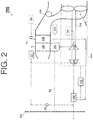
- FIG. 2 a schematic of an environmental control system 200 (e.g., an embodiment of system 100), as it could be installed on an aircraft, where in operation the environmental control system 200 mixes fresh air (e.g., a first medium) with bleed air (e.g., a second medium), is depicted according to an embodiment.
- fresh air e.g., a first medium
- bleed air e.g., a second medium
- Components of the system 100 that are similar to the environmental control system 200 have been reused for ease of explanation, by using the same identifiers, and are not re-introduced.
- Alternative components of the environmental control system 200 include an inlet 201, and outlet 202.
- Alternative components of the environmental control system 200 include a compressing device 210, which comprises a compressor 212, a turbine 214, a shaft 218, and a fan 316, along with an outflow heat exchanger 230, a water collector 271, and a water collector 272.
- the environmental control system 200 provides a path for the medium denoted by the dot-dashed line F2 (where the medium can be provided from the chamber 102 into the environmental control system 200).
- the turbine 214 can be a dual use and/or a dual entry turbine.
- a dual use turbine is configured to receive flows of different mediums in the alternative.
- a duel entry turbine is configured with multiple nozzles that can receive flows of mediums at different entry point, such that multiple flows can be received simultaneously.
- the turbine 214 can include a plurality of inlet gas flow paths, such as an inner flow path and an outer flow path, to enable mixing of alternative medium flows at the exit of the turbine 214.
- the inner flow path can be a first diameter
- the outer flow path can be a second diameter.
- the inner flow path can align with one of the first or second nozzles
- the outer flow path can align with the other of the first or second nozzles.
- a medium when a medium is being provided from the chamber 102 (e.g., a pressurized volume, cabin of the aircraft, or cabin and flight deck of the aircraft), the medium can be referred as chamber discharge air (also known as pressured air or cabin discharge air).
- chamber discharge air also known as pressured air or cabin discharge air.
- an exhaust from the environmental control system 200 can be sent to an outlet (e.g., releases to ambient air through the shell 119).
- the medium when a medium is being provided from the inlet 201, the medium can be referred to as fresh outside air (also known as fresh air or outside air).
- fresh outside air also known as fresh air or outside air
- the fresh outside air can be procured with one or more scooping mechanisms, such as an impact scoop or a flush scoop.
- the inlet 201 can be considered a fresh air inlet.
- the primary heat exchanger 120 cools the pressure high-temperature air to nearly ambient temperature to produce cool high pressure air.
- This cool high pressure air enters the condenser 162, where it is further cooled by air from the turbine 214 of the compressing device 210.
- the cool high pressure air Upon exiting the condenser 162, the cool high pressure air enters the water extractor 272 so that moisture in the air is removed.
- the cool high pressure air enters the turbine 214 through a nozzle (e.g., a first nozzle).
- the cool high pressure air is expanded across the turbine 214 and work extracted from the cool high pressure air.
- This extracted work drives the compressor 212 used to compress fresh outside air.
- This extracted work also drives the fan 216, which is used to move air through the primary heat exchanger 120 and the secondary heat exchanger 130 (also known as ram air heat exchangers).
- the act of compressing the fresh outside air heats the fresh outside air.
- the compressed fresh outside air enters the outflow heat exchanger 230 and is cooled by the chamber discharge air to produce cooled compressed fresh outside air.
- the cooled compressed fresh outside air then enters the secondary heat exchanger 130 and is further cooled to nearly ambient temperature.
- the air exiting the secondary heat exchanger 130 then enters the water extractor 271, where any free moisture is removed, to produce cool medium pressure air.
- This cool medium pressure air then enters the turbine 214 through a nozzle (e.g., a second nozzle).
- the cool medium pressure air is expanded across the turbine 214 and work extracted from the cool high pressure air.
- the chamber discharge air exiting from the outflow heat exchanger 230 can then be sent to an outlet 202.
- the outlet 202 can be a cabin pressure control system that utilized the energy of the chamber discharge air.
- the two air flows (e.g., the fresh outside air sourcing from 201 and the bleed air sourcing from inlet 101) are mixed at an exit of the turbine 214 to produce mixed air.
- the exit of the turbine 214 can be considered a first mixing point of the environmental control system 200.
- the mixed air leaves the turbine 214 and enters the condenser 162 to cool the bleed air leaving the primary heat exchanger 120.
- the mixed air is then sent to condition the chamber 102.
- This low altitude operation can be consider a low altitude mode.
- the low altitude mode can be used for ground and low altitude flight conditions, such as ground idle, taxi, take-off, and hold conditions.
- the fresh outside air can be mixed downstream of the turbine 214 (rather than at the exit of the turbine 214 or at the first mixing point).
- the air exiting the water extractor 271 is the cool medium pressure air.
- This cool medium pressure air is directed by the valve V2 to downstream of the turbine 214 and/or downstream of the condenser 162.
- the location at which this cool medium pressure air mixes with the bleed air, which is sourced from the inlet 101 and exiting the condenser 162, can be considered a second mixing point of the environmental control system 200.
- This high altitude operation can be considered a high altitude mode.
- the high altitude mode can be used at high altitude cruise, climb, and descent flight conditions.
- fresh air aviation requirements for passengers are met by mixing the two air flows (e.g., the fresh outside air sourcing from 201 and the bleed air sourcing from inlet 101).
- an amount of bleed air needed can be reduced.
- the environmental control system 200 provides bleed air reduction ranging from 40% to 75% to provide higher efficiencies with respect to engine fuel burn than contemporary airplane air systems.
- FIGS. 3 and 4 illustrate variations of the environmental control system 200.
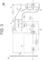
- FIG. 3 a schematic of an environmental control system 300 (e.g., an embodiment of the environmental control system 200) is depicted according to an embodiment. Components of the systems 100 and 200 that are similar to the environmental control system 300 have been reused for ease of explanation, by using the same identifiers, and are not re-introduced.
- Alternative components of the environmental control system 300 include a compressing device 310, which comprises a compressor 312, a turbine 314, and a shaft 315, and a rotating device 316 (e.g., turbine driven fan), which comprises a turbine 317 and a fan 319, along with a secondary path for the medium sourced from the inlet 101 (e.g., a valve V3 can provide the medium from the inlet 101 to an inlet of the turbine 317).
- a compressing device 310 which comprises a compressor 312, a turbine 314, and a shaft 315
- a rotating device 316 e.g., turbine driven fan
- a secondary path for the medium sourced from the inlet 101 e.g., a valve V3 can provide the medium from the inlet 101 to an inlet of the turbine 317.
- the turbine 214 can be a dual use and/or a dual entry turbine.
- the environmental control system 300 operates similarly to the environmental control system 200 in that different mixing points are utilized based on the mode of operation.
- the environmental control system 300 separates the ram air fan (e.g., fan 216) from the air cycle machine (e.g., the compressing device 210) and provides the ram air fan within the rotating device 316.
- the turbine 317 of the rotating device 316 is powered by the bleed air sourced from the inlet 101 flowing through the valve V3.
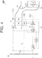
- FIG. 4 a schematic of an environmental control system 400 (e.g., an embodiment of the environmental control system 200) is depicted according to an embodiment.
- Components of the systems 100, 200, and 300 that are similar to the environmental control system 400 have been reused for ease of explanation, by using the same identifiers, and are not re-introduced.
- Alternative components of the environmental control system 400 include a rotating device 416, which comprises a motor 417 and a fan 419.
- the environmental control system 400 operates similarly to the environmental control system 200 in that different mixing points are utilized based on the mode of operation.
- the environmental control system 400 separates the ram air fan (e.g., fan 216) from the air cycle machine (e.g., the compressing device 210) and provides the ram air fan within the rotating device 416.
- the motor 417 of the rotating device 416 is powered by electric power.
- FIG. 5 a schematic of an environmental control system 500 (e.g., an embodiment of system 100), as it could be installed on an aircraft, where in operation the environmental control system 500 mixes fresh air (e.g., a first medium) with bleed air (e.g., a second medium), is depicted according to an embodiment.
- fresh air e.g., a first medium
- bleed air e.g., a second medium
- Alternative components of the environmental control system 500 include a compressing device 510 that comprises a compressor 512, a shaft 513, a turbine 514, and a turbine 515, along with paths for the medium denoted by the dot-dashed lines F3 and F4 (where the medium can be provided from the outflow heat exchanger 230 through a valve V5 to the shell 119 or the turbine 515).
- the turbine 514 can be a dual use and/or a dual entry turbine.
- the primary heat exchanger 120 cools the pressure high-temperature air to nearly ambient temperature to produce cool high pressure air.
- This cool high pressure air enters the condenser 162, where it is further cooled by air from the turbine 514 of the compressing device 510.
- the cool high pressure air Upon exiting the condenser 162, the cool high pressure air enters the water extractor 272 so that moisture in the air is removed.
- the cool high pressure air enters the turbine 514 through a nozzle (e.g., a first nozzle).
- the cool high pressure air is expanded across the turbine 514 and work extracted from the cool high pressure air. This extracted work drives the compressor 512 used to compress fresh outside air. This extracted work also drives the fan 516, which is used to move air through the primary heat exchanger 120 and the secondary heat exchanger 130.
- the act of compressing the fresh outside air heats the fresh outside air.
- the compressed fresh outside air enters the outflow heat exchanger 230 and is cooled by the chamber discharge air to produce cooled compressed fresh outside air.
- the cooled compressed fresh outside air then enters the secondary heat exchanger 130 and is further cooled to nearly ambient temperature.
- the air exiting the secondary heat exchanger 130 then enters the water extractor 271, where any free moisture is removed, to produce cool medium pressure air.
- This cool medium pressure air then enters the turbine 514 through a nozzle (e.g., a second nozzle).
- the cool medium pressure air is expanded across the turbine 514 and work extracted from the cool high pressure air.
- the two air flows (e.g., the fresh outside air sourcing from 201 and the bleed air sourcing from inlet 101) are mixed at an exit of the turbine 514 to produce mixed air.
- the exit of the turbine 514 can be considered a first mixing point of the environmental control system 200.
- the mixed air leaves the turbine 514 and enters the condenser 162 to cool the bleed air leaving the primary heat exchanger 120.
- the mixed air is then sent to condition the chamber 102.
- This low altitude operation can be consider a low altitude mode.
- the low altitude mode can be used for ground and low altitude flight conditions, such as ground idle, taxi, take-off, and hold conditions.
- the fresh outside air can be mixed downstream of the turbine 514 (rather than at the exit of the turbine 514 or at the first mixing point).
- the air exiting the water extractor 271 is the cool medium pressure air.
- This cool medium pressure air is directed by the valve V2 to downstream of the turbine 514 and/or downstream of the condenser 162.
- the location at which this cool medium pressure air mixes with the bleed air, which is sourced from the inlet 101 and exiting the condenser 162, can be considered a second mixing point of the environmental control system 200.
- energy in the cabin discharge air exiting from the outflow heat exchanger 230 is used to power the compressor 512 by feeding (e.g., the dot-dashed line F3) the cabin discharge air to the turbine 515.
- the additional or second turbine 515 included in the compressing device 510 can be fed hot air from the valve V5 (e.g., an outflow valve).
- the compressor 512 receives power from both the bleed air (via turbine 512) and the cabin discharge air (via turbine 515). If the energy is not chosen to be utilized, the cabin discharge air can be sent overboard through the shell 119, as shown by the dot-dashed line F4.
- This high altitude operation can be considered a high altitude mode.
- the high altitude mode can be used at high altitude cruise, climb, and descent flight conditions.
- fresh air aviation requirements for passengers are met by mixing the two air flows (e.g., the fresh outside air sourcing from 201 and the bleed air sourcing from inlet 101).
- an amount of bleed air needed can be reduced.
- the environmental control system 500 provides bleed air reduction ranging from 40% to 75% to provide higher efficiencies with respect to engine fuel burn than contemporary airplane air systems.
- FIGS. 6 and 7 illustrate variations of the environmental control system 200.
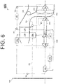
- FIG. 6 a schematic of an environmental control system 600 (e.g., an embodiment of the environmental control system 500) is depicted according to an embodiment.
- Components of the systems 100, 200, 300, 400, and 500 that are similar to the environmental control system 600 have been reused for ease of explanation, by using the same identifiers, and are not re-introduced.
- Alternative components of the environmental control system 600 include a compressing device 610, which comprises a compressor 612, a shaft 613, a turbine 614, and a turbine 615 (where the turbine 615 can receive the medium from valve V5).
- the turbine 614 can be a dual use and/or a dual entry turbine.
- the environmental control system 600 operates similarly to the environmental control system 500 in that different mixing points are utilized based on the mode of operation.
- the environmental control system 600 separates the ram air fan (e.g., fan 516) from the air cycle machine (e.g., the compressing device 510) and provides the ram air fan within the rotating device 316.
- the turbine 317 of the rotating device 316 is powered by the bleed air sourced from the inlet 101 flowing through the valve V3.
- energy in the cabin discharge air exiting from the outflow heat exchanger 230 is used to power the compressor 612 by feeding (e.g., the dot-dashed line F3) the cabin discharge air to the turbine 615.
- the additional or second turbine 615 included in the compressing device 610 can be fed hot air from the valve V5 (e.g., an outflow valve).
- the compressor 612 receives power from both the bleed air (via turbine 614) and the cabin discharge air (via turbine 615). If the energy is not chosen to be utilized, the cabin discharge air can be sent overboard through the shell 119, as shown by the dot-dashed line F4.
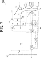
- FIG. 7 a schematic of an environmental control system 700 (e.g., an embodiment of the environmental control system 500) is depicted according to an embodiment.
- Components of the systems 100, 200, 300, and 400 that are similar to the environmental control system 700 have been reused for ease of explanation, by using the same identifiers, and are not re-introduced.
- the environmental control system 700 operates similarly to the environmental control system 500 in that different mixing points are utilized based on the mode of operation.
- the environmental control system 700 separates the ram air fan (e.g., fan 516) from the air cycle machine (e.g., the compressing device 510) and provides the ram air fan within the rotating device 416.
- the motor 417 of the rotating device 416 is powered by electric power.
- the above systems 100, 200, 300, 400, 500, 600, and 700 can further utilize an enhanced compressor as the compressor 112 (or compressors 312, 512, and 612) to address compressor range concerns during operations of the system 100.
- an enhanced compressor as the compressor 112 (or compressors 312, 512, and 612) to address compressor range concerns during operations of the system 100.
- embodiments herein provide an environmental control system that utilizes bleed pressures to power the environmental control system and to provide cabin pressurization and cooling at a high engine fuel burn efficiency, along with including the enhanced compressor that has high efficiency over a much wider corrected flow and pressure ratio range than the conventional centrifugal compressor.
- the enhanced compressor can include one or more of a compressor with high rotor backsweep, shroud bleed, and a low solidity diffuser; a variable vaned diffuser, and a mixed flow compressor. The enhanced compressor will now be described with respect to FIGS. 8-11 .
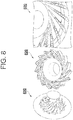
- FIG. 8 is a diagram of schematics of diffusers of a compressing device according to an embodiment.
- FIG. 8 illustrates a plurality of diffusers, a schematic 810 of a low solidity diffuser, a schematic 820 of a curved channel diffusor, and a schematic 830 of a variable vaned diffuser.
- a diffuser converts the dynamic pressure of the medium flowing downstream of the rotor into static pressure rise by gradually slowing/diffusing a velocity of the medium (e.g., increases static pressure leaving the rotor).
- the diffuser can be vaneless, vaned or an alternating combination.
- one these diffusers 810, 820, and 830 can be utilized within the compressor 112 (or compressors 312, 512, and 612) (e.g., at position 1106 described below with respect to FIG. 11 ).
- the low solidity diffuser has a smaller number of vanes and provides a wide operating range with a lower efficiency.
- the curved channel diffuser extends arches each of the vanes and provides a narrow operating range with a high efficiency.
- the variable vaned diffuser comprises a plurality of vanes, each of which is configured to rotate about a pin as an articulating member moves the plurality of vanes, and provides a very high operating range with a high efficiency.
- a single diffuser that has a combination of two or more of the diffusers 810, 820, and 830 can also be utilized.
- FIGS. 9-10 the enhanced compressor will now be described with respect to the compressor 112 (or compressors 312, 512, and 612), including a high rotor backsweep with shroud bleed and a low solidity diffuser.
- FIG. 9 is a diagram of schematics of a compressor rotor backsweep according to an embodiment.
- FIG. 9 illustrates a first rotor 900, with a plurality of blades 902, according to an embodiment.
- a reference line 904 extends radially from a center of the rotor 900.
- a dotted-line 906 tracks a direction of the rotor blade 902, if the rotor blade 902 were to be extended from a circumferential edge of the rotor 900.
- the direction of the rotor blade 902 (e.g., dotted-line 906) is in parallel with the reference line 904, which indicates no rotor backsweep.
- FIG. 9 also illustrates a high rotor backsweep 950, with a plurality of blades 952, according to an embodiment.
- a reference line 954 extends radially from a center of the rotor 950.
- a dotted-line 956 tracks a direction of the rotor blade 952, if the rotor blade 952 were to be extended from a circumferential edge of the rotor 950.
- the direction of the rotor blade 952 (e.g., dotted-line 956) is not in parallel with the reference line 954, which indicates a rotor backsweep.
- the backsweep can be predetermined during manufacturing of the rotor, and can range from 0° to 90°. Embodiments of the backsweep include, but are not limited to, 0°, 30°, 42°, 45°, and 52°.
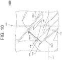
- FIG. 10 illustrates a shroud bleed placement diagram 1000, which includes a plurality of demarcations and lines overlaying a greyed-out view of a portion of a rotor, according to an embodiment.
- rotor blades or impeller blades 1002 e.g., impeller blades 1002.1 and 1002.2 bound a flow path.
- a shroud tip 1003 of the impeller blade 1002.1 i.e., an impeller blade leading edge
- a throat 1005 of the flow path is formed.
- a plane 1016 is formed at a location where the throat 1005 contacts the shroud suction surface 1004 of the impeller blade 1002.2.
- the plane 1016 is perpendicular to an axis of rotation 1017 of the rotor itself.
- the plane 1016 can be utilized to offset 1021 a shroud bleed 1023.
- the offset 1021 can be selected from a range, such as a range from 0 to 0.90 inches.
- the shroud bleed 1023 can be an opening for allowing a portion of a medium in the flow path to bleed out of or into the flow path instead of exiting the rotor.
- the shroud bleed 1023 can be a circumferentially located on a housing of the rotor.
- the shroud bleed 1023 can comprise one or more openings, each of which can be segmented at fixed or varying intervals, lengths, and/or patterns, to accommodate different bleed rates.
- the shroud bleed 1023 can be holes, slots, cuts, etc.
- the shroud bleed 1023 can be defined by an area, such as a total open area that is a percentage, e.g., 0 to 50% of a total rotor inlet throat area 1024.
- the total rotor inlet throat area 1024 is defined by the area 1024 between each pair of impeller blades 1002.
- FIG. 11 is a diagram of schematics of a mixed flow channel according to an embodiment.
- FIG. 11 illustrates a cross section view 1100 of the compressor 112 (or compressors 312, 512, and 612).
- the compressor 112 (or compressors 312, 512, and 612), comprises an inlet 1102 and an outlet 1104, which define a flow path. That is, the flow path between the inlet 1102 and the outlet 1104 is the mixed flow channel.
- the mixed flow channel can house a diffuser at position 1106 and a rotor at position 1108.
- a shape of the mixed flow channel can be selected to be between a range of a channel 1110.1 to a channel 1110.2.
- the channel 1110.1 is a straight flow path, where a flow of a medium through the channel 1110.1 is parallel to an axis of rotation of the rotor.
- the channel 1110.2 is a bent flow path, where the flow of the medium through the channel 1110.2 begins at inlet 1102 in parallel with the axis of rotation of the rotor and ends at outlet 1104 perpendicular to the axis of rotation of the rotor.
Landscapes
- Engineering & Computer Science (AREA)
- Mechanical Engineering (AREA)
- General Engineering & Computer Science (AREA)
- General Health & Medical Sciences (AREA)
- Pulmonology (AREA)
- Aviation & Aerospace Engineering (AREA)
- Health & Medical Sciences (AREA)
- Physics & Mathematics (AREA)
- Combustion & Propulsion (AREA)
- Chemical & Material Sciences (AREA)
- Geometry (AREA)
- Fluid Mechanics (AREA)
- Thermal Sciences (AREA)
- Structures Of Non-Positive Displacement Pumps (AREA)
Applications Claiming Priority (1)
| Application Number | Priority Date | Filing Date | Title |
|---|---|---|---|
| US201662341845P | 2016-05-26 | 2016-05-26 |
Publications (2)
| Publication Number | Publication Date |
|---|---|
| EP3249198A1 true EP3249198A1 (de) | 2017-11-29 |
| EP3249198B1 EP3249198B1 (de) | 2022-01-26 |
Family
ID=58800701
Family Applications (1)
| Application Number | Title | Priority Date | Filing Date |
|---|---|---|---|
| EP17173077.3A Active EP3249198B1 (de) | 2016-05-26 | 2017-05-26 | Mischen von stau- und zapfluft in einem turbinensystem mit doppeltem eingang |
Country Status (5)
| Country | Link |
|---|---|
| US (1) | US11047237B2 (de) |
| EP (1) | EP3249198B1 (de) |
| CN (1) | CN107472541B (de) |
| BR (1) | BR102017011087B1 (de) |
| CA (1) | CA2968742C (de) |
Cited By (6)
| Publication number | Priority date | Publication date | Assignee | Title |
|---|---|---|---|---|
| EP3587269A1 (de) * | 2018-06-26 | 2020-01-01 | Hamilton Sundstrand Corporation | Flugzeugumgebungskontrollsystem |
| US10882623B2 (en) | 2017-01-27 | 2021-01-05 | Hamilton Sunstrand Corporation | Advanced environmental control system in an integrated split pack arrangement with two bleed/outflow heat exchangers |
| EP3945024A1 (de) * | 2020-07-30 | 2022-02-02 | Hamilton Sundstrand Corporation | Flugzeugklimaregelungssystem |
| US11840344B2 (en) | 2020-07-30 | 2023-12-12 | Hamilton Sundstrand Corporation | Aircraft environmental control system |
| US11851192B2 (en) | 2020-07-30 | 2023-12-26 | Hamilton Sundstrand Corporation | Aircraft environmental control system |
| US20260028126A1 (en) * | 2024-07-29 | 2026-01-29 | Hamilton Sundstrand Corporation | Additively manufactured heat exchanger and diffuser pipe coupled to a compressor stage |
Families Citing this family (18)
| Publication number | Priority date | Publication date | Assignee | Title |
|---|---|---|---|---|
| US11459110B2 (en) * | 2016-04-22 | 2022-10-04 | Hamilton Sunstrand Corporation | Environmental control system utilizing two pass secondary heat exchanger and cabin pressure assist |
| EP3248877B1 (de) | 2016-05-26 | 2023-05-10 | Hamilton Sundstrand Corporation | Mischen von neben- und stauluft an einem turbineneinlass |
| US11506121B2 (en) | 2016-05-26 | 2022-11-22 | Hamilton Sundstrand Corporation | Multiple nozzle configurations for a turbine of an environmental control system |
| US10604263B2 (en) | 2016-05-26 | 2020-03-31 | Hamilton Sundstrand Corporation | Mixing bleed and ram air using a dual use turbine system |
| US10773807B2 (en) | 2016-05-26 | 2020-09-15 | Hamilton Sunstrand Corporation | Energy flow of an advanced environmental control system |
| EP3248879B1 (de) | 2016-05-26 | 2021-06-30 | Hamilton Sundstrand Corporation | Mischen von zapf- und stauluft unter verwendung einer luftkreislaufmaschine mit zwei turbinen |
| BR102017010900B1 (pt) | 2016-05-26 | 2023-04-04 | Hamilton Sundstrand Corporation | Dispositivo de compressão, e, sistema de controle ambiental de uma aeronave |
| US11511867B2 (en) | 2016-05-26 | 2022-11-29 | Hamilton Sundstrand Corporation | Mixing ram and bleed air in a dual entry turbine system |
| US11148813B2 (en) | 2018-04-03 | 2021-10-19 | Hamilton Sundstrand Corporation | Liquid reheater heat exchanger in an air cycle system |
| WO2020095477A1 (ja) * | 2018-11-06 | 2020-05-14 | 株式会社Ihi | 航空機用空調装置 |
| US11104442B2 (en) * | 2019-03-19 | 2021-08-31 | Hamilton Sundstrand Corporation | Shoestring environmental control system for an aircraft |
| US10994848B2 (en) | 2019-03-19 | 2021-05-04 | Hamilton Sunstrand Corporation | Environmental control system for an aircraft |
| US11377217B2 (en) | 2019-06-11 | 2022-07-05 | Hamilton Sundstrand Corporation | Using bleed air to supply outside air to a cabin |
| US11332252B2 (en) * | 2019-06-11 | 2022-05-17 | Hamilton Sundstrand Corporation | Using bleed air to supply outside air to a cabin |
| US20210053687A1 (en) * | 2019-08-20 | 2021-02-25 | Hamilton Sundstrand Corporation | Air conditioning system with integrated cabin pressure control |
| US11994088B2 (en) | 2021-10-01 | 2024-05-28 | Hamilton Sundstrand Corporation | Ambient air environmental control system |
| US12326162B2 (en) | 2022-06-03 | 2025-06-10 | Hamilton Sundstrand Corporation | Integrated radial diffuser with movable diffuser hub |
| US12152495B1 (en) | 2023-07-21 | 2024-11-26 | Hamilton Sundstrand Corporation | Turbine with a plurality of inlet nozzles |
Citations (7)
| Publication number | Priority date | Publication date | Assignee | Title |
|---|---|---|---|---|
| US5299763A (en) * | 1991-12-23 | 1994-04-05 | Allied-Signal Inc. | Aircraft cabin air conditioning system with improved fresh air supply |
| US5461882A (en) * | 1994-07-22 | 1995-10-31 | United Technologies Corporation | Regenerative condensing cycle |
| US20010004837A1 (en) * | 1999-12-27 | 2001-06-28 | Alfred Sauterleute | Air-conditioning system for airplane cabin |
| US20040055309A1 (en) * | 2002-09-19 | 2004-03-25 | Siemens Westinghouse Power Corporation | Water recovery from combustion turbine exhaust |
| EP2597036A2 (de) * | 2011-11-28 | 2013-05-29 | Hamilton Sundstrand Corporation | Luftkreislaufsystem mit gemischtem Strom für Flugzeugklimaanlage |
| US20130136590A1 (en) * | 2011-01-27 | 2013-05-30 | Hirotaka Higashimori | Radial turbine |
| JP5909163B2 (ja) * | 2012-08-27 | 2016-04-26 | 三菱重工業株式会社 | 二圧式ラジアルタービンの運用方法 |
Family Cites Families (82)
| Publication number | Priority date | Publication date | Assignee | Title |
|---|---|---|---|---|
| US2800002A (en) | 1954-02-02 | 1957-07-23 | Garrett Corp | Cabin refrigeration system |
| GB994856A (en) | 1963-04-10 | 1965-06-10 | Normalair Ltd | Improvements in or relating to air conditioning systems |
| US3428242A (en) | 1967-06-02 | 1969-02-18 | United Aircraft Corp | Unitary simple/bootstrap air cycle system |
| US4021215A (en) | 1976-05-03 | 1977-05-03 | United Technologies Corporation | Dual combined cycle air-conditioning system |
| US4261416A (en) | 1979-02-23 | 1981-04-14 | The Boeing Company | Multimode cabin air conditioning system |
| US4419926A (en) * | 1980-09-02 | 1983-12-13 | Lockheed Corporation | ESC energy recovery system for fuel-efficient aircraft |
| US4374469A (en) | 1980-12-24 | 1983-02-22 | United Technologies Corporation | Variable capacity air cycle refrigeration system |
| US4604028A (en) | 1985-05-08 | 1986-08-05 | General Electric Company | Independently actuated control valves for steam turbine |
| US4769051A (en) * | 1987-10-19 | 1988-09-06 | United Technologies Corporation | Filtered environmental control system |
| US5473899A (en) | 1993-06-10 | 1995-12-12 | Viteri; Fermin | Turbomachinery for Modified Ericsson engines and other power/refrigeration applications |
| DE4320302C2 (de) | 1993-06-18 | 1996-09-12 | Daimler Benz Aerospace Airbus | Anordnung zur Energiegewinnung an Bord eines Flugzeuges, insbesondere eines Passagierflugzeuges |
| US5911388A (en) | 1997-01-15 | 1999-06-15 | Sundstrand Corporation | Environmental control system with energy recovery and bleed air assist |
| US5967461A (en) | 1997-07-02 | 1999-10-19 | Mcdonnell Douglas Corp. | High efficiency environmental control systems and methods |
| US5899085A (en) | 1997-08-01 | 1999-05-04 | Mcdonnell Douglas Corporation | Integrated air conditioning and power unit |
| US6199387B1 (en) | 1999-07-30 | 2001-03-13 | Liebherr-Aerospace Lindenberg Gmbh | Air-conditioning system for airplane cabin |
| US6427471B1 (en) | 2000-02-29 | 2002-08-06 | Shimadzu Corporation | Air cycle machine and air conditioning system using the same |
| US6257003B1 (en) | 2000-08-04 | 2001-07-10 | Hamilton Sundstrand Corporation | Environmental control system utilizing two air cycle machines |
| DE10047623C1 (de) | 2000-09-26 | 2002-05-23 | Liebherr Aerospace Gmbh | Klimatisierungssystem für Flugzeuge |
| US6681592B1 (en) | 2001-02-16 | 2004-01-27 | Hamilton Sundstrand Corporation | Electrically driven aircraft cabin ventilation and environmental control system |
| US6845630B2 (en) | 2001-02-16 | 2005-01-25 | Hamilton Sundstrand Corporation | Electric power and cooling system for an aircraft |
| US6526775B1 (en) | 2001-09-14 | 2003-03-04 | The Boeing Company | Electric air conditioning system for an aircraft |
| US6681591B2 (en) | 2001-10-19 | 2004-01-27 | Hamilton Sundstrand | Cabin air temperature control with cooling of recirculated air |
| US6615606B2 (en) | 2002-01-10 | 2003-09-09 | Hamilton Sundstrand | Dual turbine bootstrap cycle environmental control system |
| US6758742B2 (en) | 2002-07-16 | 2004-07-06 | Delphi Technologies, Inc. | Air partitioning device for air conditioning system |
| DE10234968A1 (de) | 2002-07-31 | 2004-02-12 | Liebherr-Aerospace Lindenberg Gmbh | Flugzeugklimaanlage |
| US7210653B2 (en) | 2002-10-22 | 2007-05-01 | The Boeing Company | Electric-based secondary power system architectures for aircraft |
| US6848261B2 (en) | 2003-04-03 | 2005-02-01 | Honeywell International Inc. | Condensing cycle with energy recovery augmentation |
| US6776002B1 (en) | 2003-04-25 | 2004-08-17 | Northrop Grumman Corporation | Magnetically coupled integrated power and cooling unit |
| GB0414341D0 (en) | 2004-06-26 | 2004-07-28 | Honeywell Normalair Garrett | Closed loop air conditioning system |
| US7334423B2 (en) | 2004-09-22 | 2008-02-26 | Hamilton Sundstrand Corporation | Dual mode condensing cycle |
| US7322202B2 (en) * | 2004-09-22 | 2008-01-29 | Hamilton Sundstrand Corporation | Electric motor driven supercharger with air cycle air conditioning system |
| US7380749B2 (en) | 2005-04-21 | 2008-06-03 | The Boeing Company | Combined fuel cell aircraft auxiliary power unit and environmental control system |
| DE102005037285A1 (de) | 2005-08-08 | 2007-02-15 | Liebherr-Aerospace Lindenberg Gmbh | Verfahren zum Betreiben einer Flugzeugklimaanlage |
| US7861536B2 (en) | 2006-03-27 | 2011-01-04 | Pratt & Whitney Canada Corp. | Ejector controlled twin air source gas turbine pressurizing air system |
| US7624592B2 (en) | 2006-05-17 | 2009-12-01 | Northrop Grumman Corporation | Flexible power and thermal architectures using a common machine |
| US7607318B2 (en) | 2006-05-25 | 2009-10-27 | Honeywell International Inc. | Integrated environmental control and auxiliary power system for an aircraft |
| DE102006042584B4 (de) | 2006-09-11 | 2008-11-20 | Airbus Deutschland Gmbh | Luftzufuhrsystem eines Flugzeuges sowie Verfahren zum Vermischen zweier Luftströme in einem Luftzufuhrsystem |
| CA2670424C (en) * | 2006-11-28 | 2014-04-08 | Shimadzu Corporation | Conditioned air supply method and supply system for aircraft |
| GB2447677B (en) | 2007-03-21 | 2011-11-16 | Honeywell Normalair Garrett | Jet pump apparatus |
| DE102007032306A1 (de) | 2007-07-11 | 2009-01-22 | Airbus Deutschland Gmbh | Klimatisierungssystem für Flugzeugkabinen |
| US8042354B1 (en) * | 2007-09-28 | 2011-10-25 | Fairchild Controls Corporation | Air conditioning apparatus |
| DE602007008583D1 (de) | 2007-11-26 | 2010-09-30 | Honeywell Aerospace Bv | Flugzeugklimaanlage |
| JP5233436B2 (ja) * | 2008-06-23 | 2013-07-10 | 株式会社日立プラントテクノロジー | 羽根無しディフューザを備えた遠心圧縮機および羽根無しディフューザ |
| JP4714779B2 (ja) | 2009-04-10 | 2011-06-29 | 東光株式会社 | 表面実装インダクタの製造方法とその表面実装インダクタ |
| DE102009031880A1 (de) | 2009-07-06 | 2011-01-20 | Airbus Operations Gmbh | Kühlkonzept für ein Brennstoffzellen-Notstromsystem |
| US8851835B2 (en) | 2010-12-21 | 2014-10-07 | Hamilton Sundstrand Corporation | Air cycle machine compressor diffuser |
| US9169024B2 (en) | 2011-05-09 | 2015-10-27 | Honeywell International Inc. | Environmental control system with closed loop pressure cycle |
| US9481468B1 (en) | 2011-07-22 | 2016-11-01 | Peter Schiff | Aircraft environmental control system |
| WO2013077924A2 (en) | 2011-09-08 | 2013-05-30 | Rolls-Royce North American Technologies Inc. | Gas turbine engine system and supersonic exhaust nozzle |
| US9028576B2 (en) * | 2011-11-09 | 2015-05-12 | Hamilton Sundstrand Corporation | Gearbox deoiler with pre-pressuring component |
| US9205925B2 (en) | 2011-11-11 | 2015-12-08 | Hamilton Sundstrand Corporation | Turbo air compressor |
| EP2602191B1 (de) | 2011-12-05 | 2016-05-11 | Hamilton Sundstrand Corporation | Motorbetriebener Kabinenluftkompressor mit verstellbarem Diffusor |
| US20140109603A1 (en) | 2011-12-29 | 2014-04-24 | Embraer S.A. | Integrated environmental control systems and methods for controlling environmental temperature of an enclosed space |
| US9109514B2 (en) | 2012-01-10 | 2015-08-18 | Hamilton Sundstrand Corporation | Air recovery system for precooler heat-exchanger |
| US9669936B1 (en) | 2012-10-24 | 2017-06-06 | The Boeing Company | Aircraft air conditioning systems and methods |
| US9033297B2 (en) | 2013-06-04 | 2015-05-19 | Hamilton Sundstrand Corporation | Cabin air compressor support bracket |
| EP2821346B1 (de) | 2013-07-04 | 2015-12-23 | Airbus Operations GmbH | Flugzeugklimaanlage und Verfahren für den Betrieb einer Flugzeugklimaanlage |
| US9103568B2 (en) | 2013-08-02 | 2015-08-11 | Hamilton Sundstrand Corporation | Compressor housing for an air cycle machine |
| US10745136B2 (en) | 2013-08-29 | 2020-08-18 | Hamilton Sunstrand Corporation | Environmental control system including a compressing device |
| US9580180B2 (en) | 2014-03-07 | 2017-02-28 | Honeywell International Inc. | Low-pressure bleed air aircraft environmental control system |
| US9656756B2 (en) | 2014-03-10 | 2017-05-23 | The Boeing Company | Turbo-compressor system and method for extracting energy from an aircraft engine |
| WO2015148853A2 (en) | 2014-03-26 | 2015-10-01 | Energy Recovery, Inc. | Hydraulic turbine system with auxiliary nozzles |
| DE102014206081A1 (de) | 2014-03-31 | 2015-10-01 | Lufthansa Technik Ag | Filter |
| EP2937287B1 (de) | 2014-04-24 | 2018-02-21 | Louis J. Bruno | Klimaregelungssystem mit shoestring-kreislauf zur maximierung der effizienz |
| EP2947012B1 (de) | 2014-05-19 | 2017-07-05 | Airbus Operations GmbH | Flugzeugklimaanlage und Verfahren für deren Betrieb |
| US10815890B2 (en) | 2014-07-03 | 2020-10-27 | General Electric Company | Jet engine cold air cooling system |
| EP2998223B1 (de) | 2014-09-19 | 2018-12-05 | Airbus Operations GmbH | Flugzeugklimaanlage und Verfahren für den Betrieb einer Flugzeugklimaanlage |
| US10000293B2 (en) | 2015-01-23 | 2018-06-19 | General Electric Company | Gas-electric propulsion system for an aircraft |
| WO2016170141A1 (en) * | 2015-04-23 | 2016-10-27 | Airbus Operations Gmbh | Electrically driven aircraft air conditioning system and method for operating such an aircraft air conditioning system |
| DE102015222193A1 (de) | 2015-11-11 | 2017-05-11 | Airbus Operations Gmbh | Flugzeugklimaanlage mit einer Kabinenabluftturbine |
| US10457401B2 (en) | 2016-05-13 | 2019-10-29 | United Technologies Corporation | Dual-use air turbine system for a gas turbine engine |
| US10604263B2 (en) | 2016-05-26 | 2020-03-31 | Hamilton Sundstrand Corporation | Mixing bleed and ram air using a dual use turbine system |
| EP3248876B1 (de) | 2016-05-26 | 2023-04-26 | Hamilton Sundstrand Corporation | Mischen von zapf- und stau-luft an einem turbineneinlass einer komprimierungsvorrichtung |
| EP3254970B1 (de) | 2016-05-26 | 2020-04-29 | Hamilton Sundstrand Corporation | Klimaregelungssystem mit einem abströmungswärmetauscher |
| BR102017010900B1 (pt) | 2016-05-26 | 2023-04-04 | Hamilton Sundstrand Corporation | Dispositivo de compressão, e, sistema de controle ambiental de uma aeronave |
| EP3248879B1 (de) | 2016-05-26 | 2021-06-30 | Hamilton Sundstrand Corporation | Mischen von zapf- und stauluft unter verwendung einer luftkreislaufmaschine mit zwei turbinen |
| US11511867B2 (en) | 2016-05-26 | 2022-11-29 | Hamilton Sundstrand Corporation | Mixing ram and bleed air in a dual entry turbine system |
| US10773807B2 (en) | 2016-05-26 | 2020-09-15 | Hamilton Sunstrand Corporation | Energy flow of an advanced environmental control system |
| US11506121B2 (en) | 2016-05-26 | 2022-11-22 | Hamilton Sundstrand Corporation | Multiple nozzle configurations for a turbine of an environmental control system |
| EP3248877B1 (de) | 2016-05-26 | 2023-05-10 | Hamilton Sundstrand Corporation | Mischen von neben- und stauluft an einem turbineneinlass |
| US10144517B2 (en) | 2016-05-26 | 2018-12-04 | Hamilton Sundstrand Corporation | Mixing bleed and ram air using a two turbine architecture with an outflow heat exchanger |
| US10295284B2 (en) * | 2016-08-18 | 2019-05-21 | The Boeing Company | Model-based method and system to detect heat exchanger fouling |
-
2017
- 2017-05-24 US US15/604,440 patent/US11047237B2/en active Active
- 2017-05-25 BR BR102017011087-7A patent/BR102017011087B1/pt active IP Right Grant
- 2017-05-26 CN CN201710385862.4A patent/CN107472541B/zh active Active
- 2017-05-26 CA CA2968742A patent/CA2968742C/en active Active
- 2017-05-26 EP EP17173077.3A patent/EP3249198B1/de active Active
Patent Citations (7)
| Publication number | Priority date | Publication date | Assignee | Title |
|---|---|---|---|---|
| US5299763A (en) * | 1991-12-23 | 1994-04-05 | Allied-Signal Inc. | Aircraft cabin air conditioning system with improved fresh air supply |
| US5461882A (en) * | 1994-07-22 | 1995-10-31 | United Technologies Corporation | Regenerative condensing cycle |
| US20010004837A1 (en) * | 1999-12-27 | 2001-06-28 | Alfred Sauterleute | Air-conditioning system for airplane cabin |
| US20040055309A1 (en) * | 2002-09-19 | 2004-03-25 | Siemens Westinghouse Power Corporation | Water recovery from combustion turbine exhaust |
| US20130136590A1 (en) * | 2011-01-27 | 2013-05-30 | Hirotaka Higashimori | Radial turbine |
| EP2597036A2 (de) * | 2011-11-28 | 2013-05-29 | Hamilton Sundstrand Corporation | Luftkreislaufsystem mit gemischtem Strom für Flugzeugklimaanlage |
| JP5909163B2 (ja) * | 2012-08-27 | 2016-04-26 | 三菱重工業株式会社 | 二圧式ラジアルタービンの運用方法 |
Cited By (14)
| Publication number | Priority date | Publication date | Assignee | Title |
|---|---|---|---|---|
| US10882623B2 (en) | 2017-01-27 | 2021-01-05 | Hamilton Sunstrand Corporation | Advanced environmental control system in an integrated split pack arrangement with two bleed/outflow heat exchangers |
| EP3587269A1 (de) * | 2018-06-26 | 2020-01-01 | Hamilton Sundstrand Corporation | Flugzeugumgebungskontrollsystem |
| US11084592B2 (en) | 2018-06-26 | 2021-08-10 | Hamilton Sundstrand Corporation | Aircraft environmental control system |
| US11851190B2 (en) | 2020-07-30 | 2023-12-26 | Hamilton Sundstrand Corporation | Aircraft environmental control system |
| US11840344B2 (en) | 2020-07-30 | 2023-12-12 | Hamilton Sundstrand Corporation | Aircraft environmental control system |
| US11851192B2 (en) | 2020-07-30 | 2023-12-26 | Hamilton Sundstrand Corporation | Aircraft environmental control system |
| EP3945024A1 (de) * | 2020-07-30 | 2022-02-02 | Hamilton Sundstrand Corporation | Flugzeugklimaregelungssystem |
| US11851191B2 (en) | 2020-07-30 | 2023-12-26 | Hamilton Sundstrand Corporation | Aircraft environmental control system |
| US11878800B2 (en) | 2020-07-30 | 2024-01-23 | Hamilton Sundstrand Corporation | Aircraft environmental control system |
| US11939065B2 (en) | 2020-07-30 | 2024-03-26 | Hamilton Sundstrand Corporation | Aircraft environmental control system |
| US11999491B2 (en) | 2020-07-30 | 2024-06-04 | Hamilton Sundstrand Corporation | Aircraft environmental control system |
| US12097962B2 (en) | 2020-07-30 | 2024-09-24 | Hamilton Sundstrand Corporation | Aircraft environmental control system |
| US12214888B2 (en) | 2020-07-30 | 2025-02-04 | Hamilton Sundstrand Corporation | Aircraft environmental control system |
| US20260028126A1 (en) * | 2024-07-29 | 2026-01-29 | Hamilton Sundstrand Corporation | Additively manufactured heat exchanger and diffuser pipe coupled to a compressor stage |
Also Published As
| Publication number | Publication date |
|---|---|
| CA2968742A1 (en) | 2017-11-26 |
| EP3249198B1 (de) | 2022-01-26 |
| CA2968742C (en) | 2025-09-02 |
| BR102017011087A2 (pt) | 2017-12-19 |
| CN107472541B (zh) | 2022-06-10 |
| US11047237B2 (en) | 2021-06-29 |
| US20170342838A1 (en) | 2017-11-30 |
| BR102017011087B1 (pt) | 2023-12-19 |
| CN107472541A (zh) | 2017-12-15 |
Similar Documents
| Publication | Publication Date | Title |
|---|---|---|
| CA2968742C (en) | MIXTURE OF INTAKE AIR AND ENGINE AIR IN A DUAL-INTAKE TURBINE SYSTEM | |
| US11511867B2 (en) | Mixing ram and bleed air in a dual entry turbine system | |
| EP3248879B1 (de) | Mischen von zapf- und stauluft unter verwendung einer luftkreislaufmaschine mit zwei turbinen | |
| EP3248876B1 (de) | Mischen von zapf- und stau-luft an einem turbineneinlass einer komprimierungsvorrichtung | |
| EP3248877B1 (de) | Mischen von neben- und stauluft an einem turbineneinlass | |
| EP3587269B1 (de) | Flugzeugumgebungskontrollsystem | |
| EP3235726B1 (de) | Klimaregelungssystem mit verbessertem verdichter | |
| EP3945024B1 (de) | Flugzeugklimaregelungssystem | |
| EP3269645A2 (de) | Mischen von zapf- und stau-luft mittels einer zweiturbinenarchitektur mit einem ausflusswärmetauscher | |
| US10731501B2 (en) | Environmental control system utilizing a motor assist and an enhanced compressor | |
| EP3248881B1 (de) | Mehrfachdüsenkonfigurationen für eine turbine eines klimaregelungssystems | |
| EP3248878A1 (de) | Mischen von zapf- und stau-luft unter verwendung eines turbinensystems mit doppelter verwendung | |
| EP3945025B1 (de) | Flugzeugklimaregelungssystem | |
| EP3492381A1 (de) | Mischen von zapf- und stauluft mittels einer zweiturbinenarchitektur mit einem ausflusswärmetauscher |
Legal Events
| Date | Code | Title | Description |
|---|---|---|---|
| PUAI | Public reference made under article 153(3) epc to a published international application that has entered the european phase |
Free format text: ORIGINAL CODE: 0009012 |
|
| STAA | Information on the status of an ep patent application or granted ep patent |
Free format text: STATUS: THE APPLICATION HAS BEEN PUBLISHED |
|
| AK | Designated contracting states |
Kind code of ref document: A1 Designated state(s): AL AT BE BG CH CY CZ DE DK EE ES FI FR GB GR HR HU IE IS IT LI LT LU LV MC MK MT NL NO PL PT RO RS SE SI SK SM TR |
|
| AX | Request for extension of the european patent |
Extension state: BA ME |
|
| STAA | Information on the status of an ep patent application or granted ep patent |
Free format text: STATUS: REQUEST FOR EXAMINATION WAS MADE |
|
| 17P | Request for examination filed |
Effective date: 20180529 |
|
| RBV | Designated contracting states (corrected) |
Designated state(s): AL AT BE BG CH CY CZ DE DK EE ES FI FR GB GR HR HU IE IS IT LI LT LU LV MC MK MT NL NO PL PT RO RS SE SI SK SM TR |
|
| STAA | Information on the status of an ep patent application or granted ep patent |
Free format text: STATUS: EXAMINATION IS IN PROGRESS |
|
| 17Q | First examination report despatched |
Effective date: 20191021 |
|
| GRAP | Despatch of communication of intention to grant a patent |
Free format text: ORIGINAL CODE: EPIDOSNIGR1 |
|
| STAA | Information on the status of an ep patent application or granted ep patent |
Free format text: STATUS: GRANT OF PATENT IS INTENDED |
|
| INTG | Intention to grant announced |
Effective date: 20210909 |
|
| RAP3 | Party data changed (applicant data changed or rights of an application transferred) |
Owner name: HAMILTON SUNDSTRAND CORPORATION |
|
| GRAS | Grant fee paid |
Free format text: ORIGINAL CODE: EPIDOSNIGR3 |
|
| GRAA | (expected) grant |
Free format text: ORIGINAL CODE: 0009210 |
|
| STAA | Information on the status of an ep patent application or granted ep patent |
Free format text: STATUS: THE PATENT HAS BEEN GRANTED |
|
| AK | Designated contracting states |
Kind code of ref document: B1 Designated state(s): AL AT BE BG CH CY CZ DE DK EE ES FI FR GB GR HR HU IE IS IT LI LT LU LV MC MK MT NL NO PL PT RO RS SE SI SK SM TR |
|
| REG | Reference to a national code |
Ref country code: GB Ref legal event code: FG4D |
|
| REG | Reference to a national code |
Ref country code: CH Ref legal event code: EP |
|
| REG | Reference to a national code |
Ref country code: AT Ref legal event code: REF Ref document number: 1465460 Country of ref document: AT Kind code of ref document: T Effective date: 20220215 |
|
| REG | Reference to a national code |
Ref country code: IE Ref legal event code: FG4D |
|
| REG | Reference to a national code |
Ref country code: DE Ref legal event code: R096 Ref document number: 602017052678 Country of ref document: DE |
|
| REG | Reference to a national code |
Ref country code: LT Ref legal event code: MG9D |
|
| REG | Reference to a national code |
Ref country code: NL Ref legal event code: MP Effective date: 20220126 |
|
| REG | Reference to a national code |
Ref country code: AT Ref legal event code: MK05 Ref document number: 1465460 Country of ref document: AT Kind code of ref document: T Effective date: 20220126 |
|
| PG25 | Lapsed in a contracting state [announced via postgrant information from national office to epo] |
Ref country code: NL Free format text: LAPSE BECAUSE OF FAILURE TO SUBMIT A TRANSLATION OF THE DESCRIPTION OR TO PAY THE FEE WITHIN THE PRESCRIBED TIME-LIMIT Effective date: 20220126 |
|
| PG25 | Lapsed in a contracting state [announced via postgrant information from national office to epo] |
Ref country code: SE Free format text: LAPSE BECAUSE OF FAILURE TO SUBMIT A TRANSLATION OF THE DESCRIPTION OR TO PAY THE FEE WITHIN THE PRESCRIBED TIME-LIMIT Effective date: 20220126 Ref country code: RS Free format text: LAPSE BECAUSE OF FAILURE TO SUBMIT A TRANSLATION OF THE DESCRIPTION OR TO PAY THE FEE WITHIN THE PRESCRIBED TIME-LIMIT Effective date: 20220126 Ref country code: PT Free format text: LAPSE BECAUSE OF FAILURE TO SUBMIT A TRANSLATION OF THE DESCRIPTION OR TO PAY THE FEE WITHIN THE PRESCRIBED TIME-LIMIT Effective date: 20220526 Ref country code: NO Free format text: LAPSE BECAUSE OF FAILURE TO SUBMIT A TRANSLATION OF THE DESCRIPTION OR TO PAY THE FEE WITHIN THE PRESCRIBED TIME-LIMIT Effective date: 20220426 Ref country code: LT Free format text: LAPSE BECAUSE OF FAILURE TO SUBMIT A TRANSLATION OF THE DESCRIPTION OR TO PAY THE FEE WITHIN THE PRESCRIBED TIME-LIMIT Effective date: 20220126 Ref country code: HR Free format text: LAPSE BECAUSE OF FAILURE TO SUBMIT A TRANSLATION OF THE DESCRIPTION OR TO PAY THE FEE WITHIN THE PRESCRIBED TIME-LIMIT Effective date: 20220126 Ref country code: ES Free format text: LAPSE BECAUSE OF FAILURE TO SUBMIT A TRANSLATION OF THE DESCRIPTION OR TO PAY THE FEE WITHIN THE PRESCRIBED TIME-LIMIT Effective date: 20220126 Ref country code: BG Free format text: LAPSE BECAUSE OF FAILURE TO SUBMIT A TRANSLATION OF THE DESCRIPTION OR TO PAY THE FEE WITHIN THE PRESCRIBED TIME-LIMIT Effective date: 20220426 |
|
| PG25 | Lapsed in a contracting state [announced via postgrant information from national office to epo] |
Ref country code: PL Free format text: LAPSE BECAUSE OF FAILURE TO SUBMIT A TRANSLATION OF THE DESCRIPTION OR TO PAY THE FEE WITHIN THE PRESCRIBED TIME-LIMIT Effective date: 20220126 Ref country code: LV Free format text: LAPSE BECAUSE OF FAILURE TO SUBMIT A TRANSLATION OF THE DESCRIPTION OR TO PAY THE FEE WITHIN THE PRESCRIBED TIME-LIMIT Effective date: 20220126 Ref country code: GR Free format text: LAPSE BECAUSE OF FAILURE TO SUBMIT A TRANSLATION OF THE DESCRIPTION OR TO PAY THE FEE WITHIN THE PRESCRIBED TIME-LIMIT Effective date: 20220427 Ref country code: FI Free format text: LAPSE BECAUSE OF FAILURE TO SUBMIT A TRANSLATION OF THE DESCRIPTION OR TO PAY THE FEE WITHIN THE PRESCRIBED TIME-LIMIT Effective date: 20220126 Ref country code: AT Free format text: LAPSE BECAUSE OF FAILURE TO SUBMIT A TRANSLATION OF THE DESCRIPTION OR TO PAY THE FEE WITHIN THE PRESCRIBED TIME-LIMIT Effective date: 20220126 |
|
| PG25 | Lapsed in a contracting state [announced via postgrant information from national office to epo] |
Ref country code: IS Free format text: LAPSE BECAUSE OF FAILURE TO SUBMIT A TRANSLATION OF THE DESCRIPTION OR TO PAY THE FEE WITHIN THE PRESCRIBED TIME-LIMIT Effective date: 20220526 |
|
| REG | Reference to a national code |
Ref country code: DE Ref legal event code: R097 Ref document number: 602017052678 Country of ref document: DE |
|
| PG25 | Lapsed in a contracting state [announced via postgrant information from national office to epo] |
Ref country code: SM Free format text: LAPSE BECAUSE OF FAILURE TO SUBMIT A TRANSLATION OF THE DESCRIPTION OR TO PAY THE FEE WITHIN THE PRESCRIBED TIME-LIMIT Effective date: 20220126 Ref country code: SK Free format text: LAPSE BECAUSE OF FAILURE TO SUBMIT A TRANSLATION OF THE DESCRIPTION OR TO PAY THE FEE WITHIN THE PRESCRIBED TIME-LIMIT Effective date: 20220126 Ref country code: RO Free format text: LAPSE BECAUSE OF FAILURE TO SUBMIT A TRANSLATION OF THE DESCRIPTION OR TO PAY THE FEE WITHIN THE PRESCRIBED TIME-LIMIT Effective date: 20220126 Ref country code: EE Free format text: LAPSE BECAUSE OF FAILURE TO SUBMIT A TRANSLATION OF THE DESCRIPTION OR TO PAY THE FEE WITHIN THE PRESCRIBED TIME-LIMIT Effective date: 20220126 Ref country code: DK Free format text: LAPSE BECAUSE OF FAILURE TO SUBMIT A TRANSLATION OF THE DESCRIPTION OR TO PAY THE FEE WITHIN THE PRESCRIBED TIME-LIMIT Effective date: 20220126 Ref country code: CZ Free format text: LAPSE BECAUSE OF FAILURE TO SUBMIT A TRANSLATION OF THE DESCRIPTION OR TO PAY THE FEE WITHIN THE PRESCRIBED TIME-LIMIT Effective date: 20220126 |
|
| PG25 | Lapsed in a contracting state [announced via postgrant information from national office to epo] |
Ref country code: AL Free format text: LAPSE BECAUSE OF FAILURE TO SUBMIT A TRANSLATION OF THE DESCRIPTION OR TO PAY THE FEE WITHIN THE PRESCRIBED TIME-LIMIT Effective date: 20220126 |
|
| PLBE | No opposition filed within time limit |
Free format text: ORIGINAL CODE: 0009261 |
|
| STAA | Information on the status of an ep patent application or granted ep patent |
Free format text: STATUS: NO OPPOSITION FILED WITHIN TIME LIMIT |
|
| REG | Reference to a national code |
Ref country code: CH Ref legal event code: PL |
|
| 26N | No opposition filed |
Effective date: 20221027 |
|
| REG | Reference to a national code |
Ref country code: BE Ref legal event code: MM Effective date: 20220531 |
|
| PG25 | Lapsed in a contracting state [announced via postgrant information from national office to epo] |
Ref country code: MC Free format text: LAPSE BECAUSE OF FAILURE TO SUBMIT A TRANSLATION OF THE DESCRIPTION OR TO PAY THE FEE WITHIN THE PRESCRIBED TIME-LIMIT Effective date: 20220126 Ref country code: LU Free format text: LAPSE BECAUSE OF NON-PAYMENT OF DUE FEES Effective date: 20220526 Ref country code: LI Free format text: LAPSE BECAUSE OF NON-PAYMENT OF DUE FEES Effective date: 20220531 Ref country code: CH Free format text: LAPSE BECAUSE OF NON-PAYMENT OF DUE FEES Effective date: 20220531 |
|
| PG25 | Lapsed in a contracting state [announced via postgrant information from national office to epo] |
Ref country code: SI Free format text: LAPSE BECAUSE OF FAILURE TO SUBMIT A TRANSLATION OF THE DESCRIPTION OR TO PAY THE FEE WITHIN THE PRESCRIBED TIME-LIMIT Effective date: 20220126 |
|
| PG25 | Lapsed in a contracting state [announced via postgrant information from national office to epo] |
Ref country code: IE Free format text: LAPSE BECAUSE OF NON-PAYMENT OF DUE FEES Effective date: 20220526 |
|
| PG25 | Lapsed in a contracting state [announced via postgrant information from national office to epo] |
Ref country code: BE Free format text: LAPSE BECAUSE OF NON-PAYMENT OF DUE FEES Effective date: 20220531 |
|
| P01 | Opt-out of the competence of the unified patent court (upc) registered |
Effective date: 20230522 |
|
| PG25 | Lapsed in a contracting state [announced via postgrant information from national office to epo] |
Ref country code: IT Free format text: LAPSE BECAUSE OF FAILURE TO SUBMIT A TRANSLATION OF THE DESCRIPTION OR TO PAY THE FEE WITHIN THE PRESCRIBED TIME-LIMIT Effective date: 20220126 |
|
| PG25 | Lapsed in a contracting state [announced via postgrant information from national office to epo] |
Ref country code: HU Free format text: LAPSE BECAUSE OF FAILURE TO SUBMIT A TRANSLATION OF THE DESCRIPTION OR TO PAY THE FEE WITHIN THE PRESCRIBED TIME-LIMIT; INVALID AB INITIO Effective date: 20170526 |
|
| PG25 | Lapsed in a contracting state [announced via postgrant information from national office to epo] |
Ref country code: MK Free format text: LAPSE BECAUSE OF FAILURE TO SUBMIT A TRANSLATION OF THE DESCRIPTION OR TO PAY THE FEE WITHIN THE PRESCRIBED TIME-LIMIT Effective date: 20220126 Ref country code: CY Free format text: LAPSE BECAUSE OF FAILURE TO SUBMIT A TRANSLATION OF THE DESCRIPTION OR TO PAY THE FEE WITHIN THE PRESCRIBED TIME-LIMIT Effective date: 20220126 |
|
| PG25 | Lapsed in a contracting state [announced via postgrant information from national office to epo] |
Ref country code: MT Free format text: LAPSE BECAUSE OF FAILURE TO SUBMIT A TRANSLATION OF THE DESCRIPTION OR TO PAY THE FEE WITHIN THE PRESCRIBED TIME-LIMIT Effective date: 20220126 |
|
| PGFP | Annual fee paid to national office [announced via postgrant information from national office to epo] |
Ref country code: DE Payment date: 20250423 Year of fee payment: 9 |
|
| PGFP | Annual fee paid to national office [announced via postgrant information from national office to epo] |
Ref country code: GB Payment date: 20250423 Year of fee payment: 9 |
|
| PGFP | Annual fee paid to national office [announced via postgrant information from national office to epo] |
Ref country code: FR Payment date: 20250423 Year of fee payment: 9 |
|
| PG25 | Lapsed in a contracting state [announced via postgrant information from national office to epo] |
Ref country code: TR Free format text: LAPSE BECAUSE OF FAILURE TO SUBMIT A TRANSLATION OF THE DESCRIPTION OR TO PAY THE FEE WITHIN THE PRESCRIBED TIME-LIMIT Effective date: 20220126 |