EP3249343A1 - Haltemodul für den lauf einer feuerwaffe, und modulare halterungsvorrichtung für feuerwaffe, die ein solches modul sowie ein haltemodul für den griff umfasst - Google Patents
Haltemodul für den lauf einer feuerwaffe, und modulare halterungsvorrichtung für feuerwaffe, die ein solches modul sowie ein haltemodul für den griff umfasst Download PDFInfo
- Publication number
- EP3249343A1 EP3249343A1 EP17172905.6A EP17172905A EP3249343A1 EP 3249343 A1 EP3249343 A1 EP 3249343A1 EP 17172905 A EP17172905 A EP 17172905A EP 3249343 A1 EP3249343 A1 EP 3249343A1
- Authority
- EP
- European Patent Office
- Prior art keywords
- housing
- holding module
- barrel
- wall
- module
- Prior art date
- Legal status (The legal status is an assumption and is not a legal conclusion. Google has not performed a legal analysis and makes no representation as to the accuracy of the status listed.)
- Granted
Links
Images

Classifications
-
- F—MECHANICAL ENGINEERING; LIGHTING; HEATING; WEAPONS; BLASTING
- F41—WEAPONS
- F41A—FUNCTIONAL FEATURES OR DETAILS COMMON TO BOTH SMALLARMS AND ORDNANCE, e.g. CANNONS; MOUNTINGS FOR SMALLARMS OR ORDNANCE
- F41A23/00—Gun mountings, e.g. on vehicles; Disposition of guns on vehicles
- F41A23/02—Mountings without wheels
- F41A23/18—Rests for supporting smallarms in non-shooting position
-
- B—PERFORMING OPERATIONS; TRANSPORTING
- B60—VEHICLES IN GENERAL
- B60R—VEHICLES, VEHICLE FITTINGS, OR VEHICLE PARTS, NOT OTHERWISE PROVIDED FOR
- B60R7/00—Stowing or holding appliances inside vehicle primarily intended for personal property smaller than suit-cases, e.g. travelling articles, or maps
- B60R7/08—Disposition of racks, clips, holders, containers or the like for supporting specific articles
- B60R7/14—Disposition of racks, clips, holders, containers or the like for supporting specific articles for supporting weapons
-
- F—MECHANICAL ENGINEERING; LIGHTING; HEATING; WEAPONS; BLASTING
- F41—WEAPONS
- F41A—FUNCTIONAL FEATURES OR DETAILS COMMON TO BOTH SMALLARMS AND ORDNANCE, e.g. CANNONS; MOUNTINGS FOR SMALLARMS OR ORDNANCE
- F41A23/00—Gun mountings, e.g. on vehicles; Disposition of guns on vehicles
- F41A23/005—Locks for connecting guns to their mountings
-
- F—MECHANICAL ENGINEERING; LIGHTING; HEATING; WEAPONS; BLASTING
- F41—WEAPONS
- F41A—FUNCTIONAL FEATURES OR DETAILS COMMON TO BOTH SMALLARMS AND ORDNANCE, e.g. CANNONS; MOUNTINGS FOR SMALLARMS OR ORDNANCE
- F41A23/00—Gun mountings, e.g. on vehicles; Disposition of guns on vehicles
- F41A23/02—Mountings without wheels
Definitions
- the technical field of the present invention is that of the support devices for firearms, and the present invention relates in particular to a modular support device for a firearm for maintaining a small caliber firearm in a secure manner, in particular to interior of a vehicle, and a butt holding module and a gun holding module for such a modular support device.
- a weapon support device makes it possible to store the weapon when it is not used, in a safe manner by immobilizing it.
- a support device in the form of a rack for storing a firearm vertically comprises an elongate support base intended to be fixed to a wall, a butt holding module located in the lower part of the support base and comprising a first housing in which is received the butt, and a gun holding module located in the upper part of the support base and comprising a second housing in which the barrel is received.
- the two modules are each formed by a parallelepiped block, with the first housing opening on the upper wall and the second housing opening on the bottom wall, the two housings being themselves parallelepipedic.
- the lower wall of the first housing is mounted on springs so as to sink when the user enters the stock of the weapon into said housing and presses on the lower wall so as to allow the barrel of the weapon to be placed opposite the second housing, and then to rise automatically when the user has released the weapon, thereby introducing the end of the barrel into the second housing and exerting a thrust to press the barrel against the bottom wall of the second housing.
- the device of the prior art described above has the disadvantage of requiring the user, when setting up or removing the weapon, it presses on the lower wall of the first housing and then rotate the weapon once the barrel has been cleared from the second housing. It is understood that this support is not done naturally in the movement of the user performing the gesture of introduction or withdrawal, and therefore the establishment and withdrawal are not quick and convenient.
- the width at least of the first housing is very close to the thickness of the stock, so that the bracket holding module of this device will fit for a given weapon, but not for a weapon with different butt sizes. This also requires the user to take more time to position the stick in front of the first housing before engaging in the latter, which further affects the speed of the installation of the weapon.
- the range of heights are limited by the movement of movement of the lower plate of the first housing, which, if it is too important, means that, in the case of a weapon having the maximum permissible height, the reaction of the springs when the user will have released the weapon will be large and the movement of the weapon may be abrupt and sudden, and abrupt and sudden manipulation is usually not desirable for a firearm.
- the object of the invention is in particular to overcome these disadvantages by proposing a support device for a firearm on which different types of firearms can be set up and removed quickly, with a simple and natural gesture.
- DE 297 857 C discloses a rifle rack comprising, in the lower part, several grooves with vertical walls each intended to receive the end of the butt of a rifle, and, in the upper part, barrel holding means according to the preamble of claim 1 , in particular means comprising a transverse bar pivotally mounted about an axis which is horizontal and in front of the guns of the rifles when they are in the stowed position, so that the bar will pivot first rearwardly under the action of the barrel of a rifle which is introduced into the rack, before tilting forward by gravity once the gun in the stowed position, position in which the bar is in front of the barrel.
- the distance between the two vertical side walls of the second housing decreases as the that one deviates from the inlet / outlet opening, the two vertical side walls being in particular each composed of a first sloping region starting from the inlet / outlet opening, of a first planar region from the first inclined region, is opposite the first planar region of the other vertical side wall and is at a constant distance therefrom from a second inclined region which extends from the first planar region, and a second planar region which starts from the second sloping region, is facing the second flat region of the other vertical side wall and is at a constant distance therefrom.
- the actuating element has an inclined or vertical contact face extending across the second housing and against which the barrel of the firearm comes into contact when it is introduced into the second housing. actuating element being displaceable as a result of said contact of the barrel against the contact face and arranged so that this displacement of the actuating element, under the action of the barrel, moves the stop element from the position of blocking at the release position.
- the stop element and the actuating element are in one piece and are in the form of a trigger pivotally mounted about a pivot axis perpendicular to the side walls of the second housing.
- stop member consisting of a notch in the region of a first end of the trigger, the remainder of the trigger forming the actuating member with the second trigger end region extending out of the second housing , so that a bearing on the second end towards the main opening of the second housing rotates the first end in the opposite direction.
- the anti-projection mechanism of the barrel holding module comprises means for resiliently biasing the stop member towards the locking position, against which the actuating element is able to move the barrel. stopping element towards the release position, the resilient biasing means consisting in particular of a leaf spring taking, where appropriate, at one end of the latter bearing on the body of the module and at its other end resting on the trigger .
- the bodies of the modules according to the present invention may be intended to be connected directly or indirectly to the fixed structure.
- the inclined walls of the first housing comprise two longitudinal walls opposite to each other and connected at each end by an end wall connecting two side walls each departing from a respective longitudinal wall at an angle thereto. last, the two end walls being curved.
- the inclined walls defining the first housing have at different heights support notches butt, each notch of an inclined wall being at the same height as a notch on another inclined wall, preferably with the where appropriate, notches along the two longitudinal walls and the two end walls.
- the modular support device may further comprise a height adjustment module comprising a first part integral with the barrel holding module and a second part integral with the butt holding module, the first part of the module for adjusting the height of the barrel holding module.
- height being movably connected to the second part so as to allow a movement of the gun holding module to bring it closer to or away from the butt holding module, thus allowing the adjustment of the distance between the module barrel hold and butt holding module.
- a gun butt retention module formed by a body intended to be connected to a fixed structure, such as an interior wall of a vehicle passenger compartment, the body comprising a top wall. , a bottom wall opposite the upper wall, and at least one side wall connecting the upper and lower walls and defining the periphery of the body, the body having a first housing which opens on the upper wall and is adapted to receive the region of free end of the butt of the firearm, the butt holding module being characterized in that the first housing is oblong and defined by walls inclined towards the upper wall of the first housing.
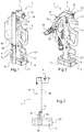
- the support device 1 comprises at least two modules, namely a butt holding module 2, intended to receive the end of the stick C1 of a firearm A, and a barrel holding module 3 for receiving the end of the barrel C2 of the firearm A.
- modules 2 and 3 are all two coupled to a height adjustment module 4, while according to a second embodiment, illustrated on the Figure 2 only the gun holding module 3 is coupled to a height adjustment module 4 '.
- Modules 4 and 4 ' will be described in more detail below.
- the butt holding module 2 has a body 5 in the form of a parallelepiped block having a bottom wall 5a, an upper wall 5b and four side walls 5c.
- the body 5 is made of a flexible material capable of protecting the butt C1 against shocks, for example when driving the vehicle.
- the material of the body 5 has a hardness of the order of 50 to 60 Shore A.
- the module 2 has a low mass.
- the material of the body could however be of a higher hardness. Indeed, the sticks of the weapons comprise more often a rubber part which will come in contact with the body.
- the body 5 is disposed in a shoe 21 of sheet steel to which it is fixed by gluing (see Figures 1 to 3 ).
- This rigid shoe facilitates fixing the body on a fixed structure such as an interior wall of the vehicle.
- a first oblong housing 6 is formed in the body 5 and opens on the upper wall 5b.
- the first housing 6 is defined by a bottom wall 6a and inclined side walls converging towards the bottom wall 6a.
- the first housing 6 comprises eight side walls shaped such that the contour of the first housing 6 in the plane of the upper wall 5b follows a general shape of ellipse. More precisely, there are two rectangular longitudinal walls 6b symmetrical with respect to the plane perpendicular to the bottom wall 6a and to which belongs the major axis of the ellipse, four flat trapezoidal side walls 6c, two on each side of each longitudinal wall 6b, and two opposite end walls 6d along the major axis of the ellipse. The end walls 6d are slightly curved, following an arc.
- the first housing 6 is flared, so that the user no longer has to take a few seconds to properly align the stock with respect to the stock holding module, as is the case in the prior art.
- the body 5 has a length of between 124 mm and 190 mm, a width of between 25 mm and 57 mm and a height of about 65 mm.
- angles of the inclined walls 6b, 6c and 6d are induced by the dimensions of the body. They are of the order of 40 ° to 60 ° relative to the vertical, and are chosen to facilitate the introduction and extraction of the butt of the weapon.
- Notches 7 are formed along the longitudinal walls 6b, over the entire length of the latter, and end walls 6d, on a median portion thereof. These notches 7 are formed at different heights and each have a horizontal face 7a on which an edge of a stick can come to press and a vertical face 7b.
- each horizontal face 7a of a notch 7 belongs to a horizontal plane to which belongs a horizontal face 7a of a notch 7 for each other wall 6b and 6d.
- the first housing 6 has five notches 7 on each of the walls 6b and 6d, regularly spaced from each other and distributed in the vicinity of the bottom wall 6a in the vicinity of the opening of the first housing 6.
- the notches 7 being formed in inclined walls, the notches 7 situated at the same height will define a horizontal support plane, formed by the horizontal faces 7a, delimited by a vertical border formed by the vertical faces 7b, and therefore a zone of reception likely to best follow the contour of the end of a stick of a given dimension. At each height of the notches 7 therefore corresponds to a given stick size.
- the butt holding module 2 thus makes it possible to stably maintain different types of firearms having different butt sizes.
- Fixing holes 5d capable of receiving fasteners, are provided on the side walls 5c of the body 5 disposed in its shoe 21, to enable the stick holding module 2 to be secured to a fixed structure, such that a vehicle interior wall.
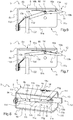
- the barrel holding module 3 has a body 8 inscribed in a rectangular parallelepiped and is formed by a sheet 9 folded so as to form a closed U shape at one end, inside which is placed a block of material 10 covering the inside of the sheet 9, so that the body 8 comprises a bottom wall 8a, an upper wall 8b and three side walls 8c.
- the block of material 10 is made of a deformable flexible material, so that it can protect the barrel C2 of a firearm A vis-à-vis the shocks while adapting to different diameters of barrel.
- the material of the barrel holding module 3 has a hardness of the order of 30 Shore A.
- the material of the holding module could however be of greater or lesser hardness.
- the body 8 has a second housing 11, provided in the block of material 10, which opens on the bottom wall 8a and on the end of the U opposite to the closed end, thus respectively forming a main opening 11a and an opening input / output 11b which communicate with each other.
- the second housing 11 is in the form of a groove delimited by two vertical side walls 11c, an end wall 11d opposite the inlet / outlet opening 11b, and a bottom wall. 11th.
- the end wall 11d is formed by a sheet folded into an open Z, the lower wing of the Z being fixed to the sheet 9 by screws and the upper wing extending vertically to inside the second housing 11.
- Each vertical side wall 11c is composed of a first sloped region 11f starting from the entry / exit opening 11b, a first planar region 11g which starts from the first sloping region 11f and extends slightly further the middle portion of the groove, a second sloping region 11h which starts from the first planar region 11g, and a second planar region 11i which starts from the second inclined region 11g.
- the first planar regions 11g define between them a first zone of the groove which has a greater width than a second zone defined between the second planar regions 11i.
- Fixing holes capable of receiving fasteners, are provided on the side walls 8c of the body 8, in order to make it possible to connect the barrel holding module 3 to a fixed structure or to a height adjustment module 4 or 4 .
- the body 8 has a length of between 94 mm and 126 mm, a width of between 34 mm and 52 mm and a height of between 63 mm and 86 mm.
- the second housing 11 has a height of about 34 mm and a length of about 120 mm.
- the width of said first and second groove areas are 15 mm and 52 mm, respectively. Such dimensions make it possible to have a barrel holding module 3 adapted to barrel diameters of 17 mm to 25 mm.
- the gun holding module 3 comprises an anti-projection mechanism 12 arranged in the second housing 11 and comprises a trigger 13 pivotally mounted about a pivot axis perpendicular to the vertical side walls 11c of the second housing 11.
- Trigger 13 consists of a very open V-shaped elongated metal strip, the major part of which constitutes a first stop member portion 13a, which corresponds to a first leg of V and a portion of the second leg of V , the end region of the second leg constituting a second portion forming an actuating element 13b.
- the stop element 13a consists in particular of a notch 13c formed at the free end of the trigger 13, the notch 13c having a stop face 13d directed towards the end wall 11d of the second housing 11, in particular facing the upper wing of the sheet forming the end wall 10d.
- the trigger 13 is received in an elongated recess formed in the bottom wall 11e of the second housing 11, with the concavity of the V directed towards the opening main 11a, and is pivotally mounted by a pivot 14 whose axis is perpendicular to the walls 10c of the second housing 11, the pivot 14 passing through a smooth bore formed in the trigger 13, at the top of the V, and through corresponding holes in the body 8 to protrude from each side wall 8c, where it is stopped in translation by a pin 15.
- the actuating element 13b extends out of the housing 11.
- a leaf spring 16 is placed between the upper side of the trigger 13 and the body 8. One end 16a of the leaf spring 16 being received in a slot formed in a projection 13e provided on the upper side of the trigger 13, in the actuating member portion 13b, and the leaf spring 16 is bolted to said actuating member portion 13b.
- the profile of the leaf spring 16 has an inflection at the pivot 14 and its other end region 16b bears against the body 8.
- the anti-projection mechanism 12, and in particular the trigger 13, is movable between a locking position and a release position.
- the trigger 13 in the locking position of the barrel C2 of a firearm.
- the stop face 13d of the notch 13c is opposite the flexible end wall 11d, between which the free end of the barrel C2 is located.
- the notch 13c thus opposes the removal of the barrel C2 and the trigger 13 is held in this position by the action of the leaf spring 16 which urges the trigger 13 to said locking position.
- the barrel C2 is securely held in position.
- the user wants to store a firearm in the support device 1 according to the present invention, it is sufficient first to engage the stick C1 in the first housing 6 of the butt holding module 2, in slightly tilting the gun. This commitment is facilitated by the fact that the first housing 6 is flared, and in particular at its ends. Then, the user rotates the firearm A to bring it back to the vertical, thereby introducing the barrel C2 into the second housing 11 to obtain its automatic locking by the anti-projection mechanism 12 in the manner described above. Simultaneously with this pivoting, the stick C1 will naturally be housed in the corresponding notches 7.
- the support that must exert the user during the introduction of the weapon, to move the trigger 13 from the locking position to the release position is in the course and in the direction of movement pivoting of the firearm A, and therefore with a natural gesture.
- the modular support device 1 makes it possible to implement place and retreat a firearm in a fast manner, with a simple and natural gesture.
- the modular support device 1 due to the arrangement of the first and second housing 6 and 11, can receive different types of firearms, having in particular different dimensions to the stick and barrel.
- the modular support device 1 also makes it possible to adapt to the height of the firearm, thanks to the height adjustment modules 4 or 4 '.
- the height adjustment module 4 comprises two telescopic tubes (here rectangular section), including a lower tube 4a slidably mounted within an upper tube 4b.
- the lower end region of the lower tube 4a is made integral with the butt holding module 2 while the upper end region of the upper tube 4b is secured to the barrel holding module 3.
- the lower tube 4a has a plurality through holes 4c distributed over the length of the lower tube 4a and adapted to correspond with at least one through hole 4d of the upper tube 4b.
- the height adjustment module 4 comprises, on the one hand, a base 18 having fixing means, such as bores for the passage of fixing, for attachment to a fixed structure, such as an inner wall of a vehicle, and, on the other hand, an arm 19 whose one end is pivotally connected about a horizontal pivot 20 and whose other end is secured to the body 8 of the gun holding module 3, the latter being held cantilevered.
- the butt retention module 2 is fixed to a fixed structure, for example the floor or said vehicle wall, at the vertical of the barrel holding module 3. In this sense, it can be considered that the butt holding module 2 and the base 18 are integral, indirectly.
- the height between the modules 2, 3 holding the stock and barrel is adjusted by moving the height of the barrel holding module 3 by simply pivoting the arm 19.
- the modular support device 1 for a firearm is well adapted to adapt to different weapons, such as a FAMAS type of assault rifle (registered trademark), a precision rifle of the type FRF2, a precision shotgun type PGM HECATE II (registered trademark) or other, that is to say, weapons of different barrel diameters, of different lengths, and different forms of buttstock.
- weapons such as a FAMAS type of assault rifle (registered trademark), a precision rifle of the type FRF2, a precision shotgun type PGM HECATE II (registered trademark) or other, that is to say, weapons of different barrel diameters, of different lengths, and different forms of buttstock.
Landscapes
- Engineering & Computer Science (AREA)
- General Engineering & Computer Science (AREA)
- Mechanical Engineering (AREA)
- Toys (AREA)
- Aiming, Guidance, Guns With A Light Source, Armor, Camouflage, And Targets (AREA)
- Vehicle Step Arrangements And Article Storage (AREA)
Applications Claiming Priority (1)
| Application Number | Priority Date | Filing Date | Title |
|---|---|---|---|
| FR1600854A FR3051746B1 (fr) | 2016-05-27 | 2016-05-27 | Dispositif de support modulaire pour arme a feu, et module de maintien de crosse et module de maintien de canon pour celui-ci |
Publications (2)
| Publication Number | Publication Date |
|---|---|
| EP3249343A1 true EP3249343A1 (de) | 2017-11-29 |
| EP3249343B1 EP3249343B1 (de) | 2018-12-12 |
Family
ID=57590542
Family Applications (1)
| Application Number | Title | Priority Date | Filing Date |
|---|---|---|---|
| EP17172905.6A Active EP3249343B1 (de) | 2016-05-27 | 2017-05-24 | Haltemodul für den lauf einer feuerwaffe, und modulare halterungsvorrichtung für feuerwaffe, die ein solches modul sowie ein haltemodul für den griff umfasst |
Country Status (2)
| Country | Link |
|---|---|
| EP (1) | EP3249343B1 (de) |
| FR (1) | FR3051746B1 (de) |
Cited By (5)
| Publication number | Priority date | Publication date | Assignee | Title |
|---|---|---|---|---|
| CN108150049A (zh) * | 2018-01-25 | 2018-06-12 | 洪瑞茜 | 一种智能枪弹柜保护装置 |
| CN108835958A (zh) * | 2018-08-22 | 2018-11-20 | 珠海优特电力科技股份有限公司 | 枪托装置及枪柜 |
| CN111765806A (zh) * | 2020-07-14 | 2020-10-13 | 北京汽车集团越野车有限公司 | 一种枪托支撑底座及车辆 |
| IT201900010611A1 (it) * | 2019-07-02 | 2021-01-02 | C S M Compagnia Di San Marco S R L | Gruppo blocca-arma, installabile in un veicolo delle forze dell’ordine e militari, compatibile con due modelli di arma |
| US11326851B1 (en) | 2021-02-24 | 2022-05-10 | James Oldham | Automatic rifle storage assembly |
Citations (9)
| Publication number | Priority date | Publication date | Assignee | Title |
|---|---|---|---|---|
| DE297857C (de) * | ||||
| US2998885A (en) * | 1960-01-08 | 1961-09-05 | Gardner A Surface | Gun rack |
| US4132318A (en) * | 1976-12-30 | 1979-01-02 | International Business Machines Corporation | Asymmetric six-degree-of-freedom force-transducer system for a computer-controlled manipulator system |
| DE19958990C1 (de) * | 1999-12-07 | 2001-03-15 | Bundesrep Deutschland | Trägerbauteil zur Halterung eines Maschinengewehres |
| US20110168649A1 (en) * | 2010-01-08 | 2011-07-14 | Stolz Gregory A | Gun storage rack |
| FR2956733A1 (fr) * | 2010-02-24 | 2011-08-26 | France Etat | Support pour arme a feu |
| US20140263107A1 (en) * | 2013-03-15 | 2014-09-18 | Covered 6, Llc | Locking Gun Rack System With Quick Deployment |
| CN104153657A (zh) * | 2014-08-21 | 2014-11-19 | 四川省永亨实业有限责任公司 | 基于长枪的枪锁装置及锁枪和开锁方法 |
| US20160120308A1 (en) * | 2014-11-05 | 2016-05-05 | Thomas Kubiniec | Revised mass weapon storage system |
-
2016
- 2016-05-27 FR FR1600854A patent/FR3051746B1/fr not_active Expired - Fee Related
-
2017
- 2017-05-24 EP EP17172905.6A patent/EP3249343B1/de active Active
Patent Citations (9)
| Publication number | Priority date | Publication date | Assignee | Title |
|---|---|---|---|---|
| DE297857C (de) * | ||||
| US2998885A (en) * | 1960-01-08 | 1961-09-05 | Gardner A Surface | Gun rack |
| US4132318A (en) * | 1976-12-30 | 1979-01-02 | International Business Machines Corporation | Asymmetric six-degree-of-freedom force-transducer system for a computer-controlled manipulator system |
| DE19958990C1 (de) * | 1999-12-07 | 2001-03-15 | Bundesrep Deutschland | Trägerbauteil zur Halterung eines Maschinengewehres |
| US20110168649A1 (en) * | 2010-01-08 | 2011-07-14 | Stolz Gregory A | Gun storage rack |
| FR2956733A1 (fr) * | 2010-02-24 | 2011-08-26 | France Etat | Support pour arme a feu |
| US20140263107A1 (en) * | 2013-03-15 | 2014-09-18 | Covered 6, Llc | Locking Gun Rack System With Quick Deployment |
| CN104153657A (zh) * | 2014-08-21 | 2014-11-19 | 四川省永亨实业有限责任公司 | 基于长枪的枪锁装置及锁枪和开锁方法 |
| US20160120308A1 (en) * | 2014-11-05 | 2016-05-05 | Thomas Kubiniec | Revised mass weapon storage system |
Cited By (8)
| Publication number | Priority date | Publication date | Assignee | Title |
|---|---|---|---|---|
| CN108150049A (zh) * | 2018-01-25 | 2018-06-12 | 洪瑞茜 | 一种智能枪弹柜保护装置 |
| CN108150049B (zh) * | 2018-01-25 | 2019-08-30 | 江西万佳保险设备有限公司 | 一种智能枪弹柜保护装置 |
| CN108835958A (zh) * | 2018-08-22 | 2018-11-20 | 珠海优特电力科技股份有限公司 | 枪托装置及枪柜 |
| CN108835958B (zh) * | 2018-08-22 | 2024-05-31 | 珠海优特电力科技股份有限公司 | 枪托装置及枪柜 |
| IT201900010611A1 (it) * | 2019-07-02 | 2021-01-02 | C S M Compagnia Di San Marco S R L | Gruppo blocca-arma, installabile in un veicolo delle forze dell’ordine e militari, compatibile con due modelli di arma |
| CN111765806A (zh) * | 2020-07-14 | 2020-10-13 | 北京汽车集团越野车有限公司 | 一种枪托支撑底座及车辆 |
| CN111765806B (zh) * | 2020-07-14 | 2023-03-14 | 北京汽车集团越野车有限公司 | 一种枪托支撑底座及车辆 |
| US11326851B1 (en) | 2021-02-24 | 2022-05-10 | James Oldham | Automatic rifle storage assembly |
Also Published As
| Publication number | Publication date |
|---|---|
| FR3051746B1 (fr) | 2019-06-14 |
| EP3249343B1 (de) | 2018-12-12 |
| FR3051746A1 (fr) | 2017-12-01 |
Similar Documents
| Publication | Publication Date | Title |
|---|---|---|
| EP3249343B1 (de) | Haltemodul für den lauf einer feuerwaffe, und modulare halterungsvorrichtung für feuerwaffe, die ein solches modul sowie ein haltemodul für den griff umfasst | |
| EP1855848B1 (de) | Schneidwerkzeug zum schneiden einer platte | |
| CH686098A5 (fr) | Dispositif de recuperation des etuis de cartouches pour une arme automatique ou semi-automatique. | |
| EP2772169B1 (de) | Abnehmbare Greifvorrichtung eines Kochbehälters, die mit Arretierungsmitteln für beide Griffe versehen ist | |
| FR3026311A1 (fr) | Talonniere de fixation d'une chaussure sur une planche de glisse | |
| CH618095A5 (de) | ||
| EP2349738B1 (de) | Schreibgerät mit einziehbarer spitze | |
| EP1354745B1 (de) | Befestigungsvorrichtung eines funktionellen Organes auf einem Autoteil der Fahrzeugstruktur und Strukturteil, die zum Teil eine solche Vorrichtung integrieren | |
| FR3043565A1 (fr) | Talonniere pour fixation de ski, fixation et ski correspondants | |
| BE1004981A3 (fr) | Chargeur a basculement de cartouches pour pistolet ou pistolet mitrailleur. | |
| BE1022029B1 (fr) | Dispositif de prehension pour le maintien de la munition lors du chargement d'un canon | |
| EP4582764A1 (de) | Anordnung zur positionierung und lagesicherung eines geschosses in einer mulde und ladehilfevorrichtung mit einer solchen anordnung | |
| EP1452393A1 (de) | Abnehmbare Hutablage für Fahrzeug und ihre Befestigungsvorrichtung | |
| EP1966562B1 (de) | Holster für eine handwaffe, z.b. eine pistole oder einen revolver | |
| EP3977036B1 (de) | Vorrichtung zum verriegeln eines waffenlaufs | |
| EP1348903B1 (de) | Befestigungseinrichtung, insbesondere für eine Einbauleuchte | |
| EP4105591B1 (de) | Vorrichtung zur positionierung eines geschosses | |
| EP4105419B1 (de) | Perfektionierte vorrichtung zum provisorischen schliessen eines öffnungselements auf einem halterungselement | |
| FR3140895A1 (fr) | Dispositif de verrouillage d’une table de coffrage sur une fourche de translation | |
| WO2003012361A1 (fr) | Etui pour arme de poing, comme par exemple un pistolet ou un revolver | |
| WO2005017440A1 (fr) | Etui pour arme de poing, comme par exemple un pistolet ou un revolver | |
| EP3361207A1 (de) | Einstellvorrichtung für einen gewehrschaft | |
| FR2836214A1 (fr) | Etui pour arme de poing, comme par exemple un pistolet ou un revolver | |
| EP3246280A1 (de) | Rückhaltevorrichtung für einen aufroller | |
| FR2711571A1 (fr) | Dispositif de sécurité pour toupie pour travail à l'arbre. |
Legal Events
| Date | Code | Title | Description |
|---|---|---|---|
| PUAI | Public reference made under article 153(3) epc to a published international application that has entered the european phase |
Free format text: ORIGINAL CODE: 0009012 |
|
| STAA | Information on the status of an ep patent application or granted ep patent |
Free format text: STATUS: THE APPLICATION HAS BEEN PUBLISHED |
|
| AK | Designated contracting states |
Kind code of ref document: A1 Designated state(s): AL AT BE BG CH CY CZ DE DK EE ES FI FR GB GR HR HU IE IS IT LI LT LU LV MC MK MT NL NO PL PT RO RS SE SI SK SM TR |
|
| AX | Request for extension of the european patent |
Extension state: BA ME |
|
| STAA | Information on the status of an ep patent application or granted ep patent |
Free format text: STATUS: REQUEST FOR EXAMINATION WAS MADE |
|
| GRAP | Despatch of communication of intention to grant a patent |
Free format text: ORIGINAL CODE: EPIDOSNIGR1 |
|
| STAA | Information on the status of an ep patent application or granted ep patent |
Free format text: STATUS: GRANT OF PATENT IS INTENDED |
|
| 17P | Request for examination filed |
Effective date: 20180529 |
|
| RBV | Designated contracting states (corrected) |
Designated state(s): AL AT BE BG CH CY CZ DE DK EE ES FI FR GB GR HR HU IE IS IT LI LT LU LV MC MK MT NL NO PL PT RO RS SE SI SK SM TR |
|
| INTG | Intention to grant announced |
Effective date: 20180629 |
|
| RIN1 | Information on inventor provided before grant (corrected) |
Inventor name: MARION, LIONEL Inventor name: PLASSE, MAXIME |
|
| GRAS | Grant fee paid |
Free format text: ORIGINAL CODE: EPIDOSNIGR3 |
|
| GRAA | (expected) grant |
Free format text: ORIGINAL CODE: 0009210 |
|
| STAA | Information on the status of an ep patent application or granted ep patent |
Free format text: STATUS: THE PATENT HAS BEEN GRANTED |
|
| AK | Designated contracting states |
Kind code of ref document: B1 Designated state(s): AL AT BE BG CH CY CZ DE DK EE ES FI FR GB GR HR HU IE IS IT LI LT LU LV MC MK MT NL NO PL PT RO RS SE SI SK SM TR |
|
| REG | Reference to a national code |
Ref country code: GB Ref legal event code: FG4D Free format text: NOT ENGLISH |
|
| REG | Reference to a national code |
Ref country code: CH Ref legal event code: EP |
|
| REG | Reference to a national code |
Ref country code: AT Ref legal event code: REF Ref document number: 1076593 Country of ref document: AT Kind code of ref document: T Effective date: 20181215 |
|
| REG | Reference to a national code |
Ref country code: IE Ref legal event code: FG4D Free format text: LANGUAGE OF EP DOCUMENT: FRENCH |
|
| REG | Reference to a national code |
Ref country code: DE Ref legal event code: R096 Ref document number: 602017001336 Country of ref document: DE |
|
| REG | Reference to a national code |
Ref country code: NL Ref legal event code: FP |
|
| REG | Reference to a national code |
Ref country code: LT Ref legal event code: MG4D |
|
| PG25 | Lapsed in a contracting state [announced via postgrant information from national office to epo] |
Ref country code: LV Free format text: LAPSE BECAUSE OF FAILURE TO SUBMIT A TRANSLATION OF THE DESCRIPTION OR TO PAY THE FEE WITHIN THE PRESCRIBED TIME-LIMIT Effective date: 20181212 Ref country code: LT Free format text: LAPSE BECAUSE OF FAILURE TO SUBMIT A TRANSLATION OF THE DESCRIPTION OR TO PAY THE FEE WITHIN THE PRESCRIBED TIME-LIMIT Effective date: 20181212 Ref country code: NO Free format text: LAPSE BECAUSE OF FAILURE TO SUBMIT A TRANSLATION OF THE DESCRIPTION OR TO PAY THE FEE WITHIN THE PRESCRIBED TIME-LIMIT Effective date: 20190312 Ref country code: BG Free format text: LAPSE BECAUSE OF FAILURE TO SUBMIT A TRANSLATION OF THE DESCRIPTION OR TO PAY THE FEE WITHIN THE PRESCRIBED TIME-LIMIT Effective date: 20190312 Ref country code: ES Free format text: LAPSE BECAUSE OF FAILURE TO SUBMIT A TRANSLATION OF THE DESCRIPTION OR TO PAY THE FEE WITHIN THE PRESCRIBED TIME-LIMIT Effective date: 20181212 Ref country code: HR Free format text: LAPSE BECAUSE OF FAILURE TO SUBMIT A TRANSLATION OF THE DESCRIPTION OR TO PAY THE FEE WITHIN THE PRESCRIBED TIME-LIMIT Effective date: 20181212 Ref country code: FI Free format text: LAPSE BECAUSE OF FAILURE TO SUBMIT A TRANSLATION OF THE DESCRIPTION OR TO PAY THE FEE WITHIN THE PRESCRIBED TIME-LIMIT Effective date: 20181212 |
|
| REG | Reference to a national code |
Ref country code: AT Ref legal event code: MK05 Ref document number: 1076593 Country of ref document: AT Kind code of ref document: T Effective date: 20181212 |
|
| PG25 | Lapsed in a contracting state [announced via postgrant information from national office to epo] |
Ref country code: GR Free format text: LAPSE BECAUSE OF FAILURE TO SUBMIT A TRANSLATION OF THE DESCRIPTION OR TO PAY THE FEE WITHIN THE PRESCRIBED TIME-LIMIT Effective date: 20190313 Ref country code: RS Free format text: LAPSE BECAUSE OF FAILURE TO SUBMIT A TRANSLATION OF THE DESCRIPTION OR TO PAY THE FEE WITHIN THE PRESCRIBED TIME-LIMIT Effective date: 20181212 Ref country code: AL Free format text: LAPSE BECAUSE OF FAILURE TO SUBMIT A TRANSLATION OF THE DESCRIPTION OR TO PAY THE FEE WITHIN THE PRESCRIBED TIME-LIMIT Effective date: 20181212 Ref country code: SE Free format text: LAPSE BECAUSE OF FAILURE TO SUBMIT A TRANSLATION OF THE DESCRIPTION OR TO PAY THE FEE WITHIN THE PRESCRIBED TIME-LIMIT Effective date: 20181212 |
|
| PG25 | Lapsed in a contracting state [announced via postgrant information from national office to epo] |
Ref country code: IT Free format text: LAPSE BECAUSE OF FAILURE TO SUBMIT A TRANSLATION OF THE DESCRIPTION OR TO PAY THE FEE WITHIN THE PRESCRIBED TIME-LIMIT Effective date: 20181212 Ref country code: CZ Free format text: LAPSE BECAUSE OF FAILURE TO SUBMIT A TRANSLATION OF THE DESCRIPTION OR TO PAY THE FEE WITHIN THE PRESCRIBED TIME-LIMIT Effective date: 20181212 Ref country code: PT Free format text: LAPSE BECAUSE OF FAILURE TO SUBMIT A TRANSLATION OF THE DESCRIPTION OR TO PAY THE FEE WITHIN THE PRESCRIBED TIME-LIMIT Effective date: 20190412 Ref country code: PL Free format text: LAPSE BECAUSE OF FAILURE TO SUBMIT A TRANSLATION OF THE DESCRIPTION OR TO PAY THE FEE WITHIN THE PRESCRIBED TIME-LIMIT Effective date: 20181212 |
|
| PG25 | Lapsed in a contracting state [announced via postgrant information from national office to epo] |
Ref country code: SK Free format text: LAPSE BECAUSE OF FAILURE TO SUBMIT A TRANSLATION OF THE DESCRIPTION OR TO PAY THE FEE WITHIN THE PRESCRIBED TIME-LIMIT Effective date: 20181212 Ref country code: IS Free format text: LAPSE BECAUSE OF FAILURE TO SUBMIT A TRANSLATION OF THE DESCRIPTION OR TO PAY THE FEE WITHIN THE PRESCRIBED TIME-LIMIT Effective date: 20190412 Ref country code: RO Free format text: LAPSE BECAUSE OF FAILURE TO SUBMIT A TRANSLATION OF THE DESCRIPTION OR TO PAY THE FEE WITHIN THE PRESCRIBED TIME-LIMIT Effective date: 20181212 Ref country code: SM Free format text: LAPSE BECAUSE OF FAILURE TO SUBMIT A TRANSLATION OF THE DESCRIPTION OR TO PAY THE FEE WITHIN THE PRESCRIBED TIME-LIMIT Effective date: 20181212 Ref country code: EE Free format text: LAPSE BECAUSE OF FAILURE TO SUBMIT A TRANSLATION OF THE DESCRIPTION OR TO PAY THE FEE WITHIN THE PRESCRIBED TIME-LIMIT Effective date: 20181212 |
|
| REG | Reference to a national code |
Ref country code: DE Ref legal event code: R097 Ref document number: 602017001336 Country of ref document: DE |
|
| PLBE | No opposition filed within time limit |
Free format text: ORIGINAL CODE: 0009261 |
|
| STAA | Information on the status of an ep patent application or granted ep patent |
Free format text: STATUS: NO OPPOSITION FILED WITHIN TIME LIMIT |
|
| PG25 | Lapsed in a contracting state [announced via postgrant information from national office to epo] |
Ref country code: SI Free format text: LAPSE BECAUSE OF FAILURE TO SUBMIT A TRANSLATION OF THE DESCRIPTION OR TO PAY THE FEE WITHIN THE PRESCRIBED TIME-LIMIT Effective date: 20181212 Ref country code: AT Free format text: LAPSE BECAUSE OF FAILURE TO SUBMIT A TRANSLATION OF THE DESCRIPTION OR TO PAY THE FEE WITHIN THE PRESCRIBED TIME-LIMIT Effective date: 20181212 Ref country code: DK Free format text: LAPSE BECAUSE OF FAILURE TO SUBMIT A TRANSLATION OF THE DESCRIPTION OR TO PAY THE FEE WITHIN THE PRESCRIBED TIME-LIMIT Effective date: 20181212 |
|
| 26N | No opposition filed |
Effective date: 20190913 |
|
| PG25 | Lapsed in a contracting state [announced via postgrant information from national office to epo] |
Ref country code: MC Free format text: LAPSE BECAUSE OF FAILURE TO SUBMIT A TRANSLATION OF THE DESCRIPTION OR TO PAY THE FEE WITHIN THE PRESCRIBED TIME-LIMIT Effective date: 20181212 |
|
| REG | Reference to a national code |
Ref country code: BE Ref legal event code: MM Effective date: 20190531 |
|
| PG25 | Lapsed in a contracting state [announced via postgrant information from national office to epo] |
Ref country code: LU Free format text: LAPSE BECAUSE OF NON-PAYMENT OF DUE FEES Effective date: 20190524 |
|
| PG25 | Lapsed in a contracting state [announced via postgrant information from national office to epo] |
Ref country code: TR Free format text: LAPSE BECAUSE OF FAILURE TO SUBMIT A TRANSLATION OF THE DESCRIPTION OR TO PAY THE FEE WITHIN THE PRESCRIBED TIME-LIMIT Effective date: 20181212 |
|
| PG25 | Lapsed in a contracting state [announced via postgrant information from national office to epo] |
Ref country code: IE Free format text: LAPSE BECAUSE OF NON-PAYMENT OF DUE FEES Effective date: 20190524 |
|
| PG25 | Lapsed in a contracting state [announced via postgrant information from national office to epo] |
Ref country code: BE Free format text: LAPSE BECAUSE OF NON-PAYMENT OF DUE FEES Effective date: 20190531 |
|
| PG25 | Lapsed in a contracting state [announced via postgrant information from national office to epo] |
Ref country code: CH Free format text: LAPSE BECAUSE OF NON-PAYMENT OF DUE FEES Effective date: 20200531 Ref country code: LI Free format text: LAPSE BECAUSE OF NON-PAYMENT OF DUE FEES Effective date: 20200531 |
|
| PG25 | Lapsed in a contracting state [announced via postgrant information from national office to epo] |
Ref country code: CY Free format text: LAPSE BECAUSE OF FAILURE TO SUBMIT A TRANSLATION OF THE DESCRIPTION OR TO PAY THE FEE WITHIN THE PRESCRIBED TIME-LIMIT Effective date: 20181212 |
|
| PG25 | Lapsed in a contracting state [announced via postgrant information from national office to epo] |
Ref country code: HU Free format text: LAPSE BECAUSE OF FAILURE TO SUBMIT A TRANSLATION OF THE DESCRIPTION OR TO PAY THE FEE WITHIN THE PRESCRIBED TIME-LIMIT; INVALID AB INITIO Effective date: 20170524 Ref country code: MT Free format text: LAPSE BECAUSE OF FAILURE TO SUBMIT A TRANSLATION OF THE DESCRIPTION OR TO PAY THE FEE WITHIN THE PRESCRIBED TIME-LIMIT Effective date: 20181212 |
|
| GBPC | Gb: european patent ceased through non-payment of renewal fee |
Effective date: 20210524 |
|
| PG25 | Lapsed in a contracting state [announced via postgrant information from national office to epo] |
Ref country code: GB Free format text: LAPSE BECAUSE OF NON-PAYMENT OF DUE FEES Effective date: 20210524 |
|
| PG25 | Lapsed in a contracting state [announced via postgrant information from national office to epo] |
Ref country code: MK Free format text: LAPSE BECAUSE OF FAILURE TO SUBMIT A TRANSLATION OF THE DESCRIPTION OR TO PAY THE FEE WITHIN THE PRESCRIBED TIME-LIMIT Effective date: 20181212 |
|
| PGFP | Annual fee paid to national office [announced via postgrant information from national office to epo] |
Ref country code: NL Payment date: 20250423 Year of fee payment: 9 |
|
| PGFP | Annual fee paid to national office [announced via postgrant information from national office to epo] |
Ref country code: DE Payment date: 20250423 Year of fee payment: 9 |
|
| PGFP | Annual fee paid to national office [announced via postgrant information from national office to epo] |
Ref country code: FR Payment date: 20250423 Year of fee payment: 9 |