EP3249355A1 - Systeme und verfahren zur bias-unterdrückung in einem nicht degenerierten mems-sensor - Google Patents
Systeme und verfahren zur bias-unterdrückung in einem nicht degenerierten mems-sensor Download PDFInfo
- Publication number
- EP3249355A1 EP3249355A1 EP17162684.9A EP17162684A EP3249355A1 EP 3249355 A1 EP3249355 A1 EP 3249355A1 EP 17162684 A EP17162684 A EP 17162684A EP 3249355 A1 EP3249355 A1 EP 3249355A1
- Authority
- EP
- European Patent Office
- Prior art keywords
- proof mass
- axis
- proof
- along
- motion
- Prior art date
- Legal status (The legal status is an assumption and is not a legal conclusion. Google has not performed a legal analysis and makes no representation as to the accuracy of the status listed.)
- Granted
Links
Images


Classifications
-
- B—PERFORMING OPERATIONS; TRANSPORTING
- B81—MICROSTRUCTURAL TECHNOLOGY
- B81B—MICROSTRUCTURAL DEVICES OR SYSTEMS, e.g. MICROMECHANICAL DEVICES
- B81B3/00—Devices comprising flexible or deformable elements, e.g. comprising elastic tongues or membranes
- B81B3/0018—Structures acting upon the moving or flexible element for transforming energy into mechanical movement or vice versa, i.e. actuators, sensors, generators
- B81B3/0021—Transducers for transforming electrical into mechanical energy or vice versa
-
- B—PERFORMING OPERATIONS; TRANSPORTING
- B81—MICROSTRUCTURAL TECHNOLOGY
- B81B—MICROSTRUCTURAL DEVICES OR SYSTEMS, e.g. MICROMECHANICAL DEVICES
- B81B3/00—Devices comprising flexible or deformable elements, e.g. comprising elastic tongues or membranes
- B81B3/0064—Constitution or structural means for improving or controlling the physical properties of a device
- B81B3/0067—Mechanical properties
- B81B3/0072—For controlling internal stress or strain in moving or flexible elements, e.g. stress compensating layers
-
- B—PERFORMING OPERATIONS; TRANSPORTING
- B81—MICROSTRUCTURAL TECHNOLOGY
- B81B—MICROSTRUCTURAL DEVICES OR SYSTEMS, e.g. MICROMECHANICAL DEVICES
- B81B7/00—Microstructural systems ; Auxiliary parts of microstructural devices or systems
- B81B7/0032—Packages or encapsulation
- B81B7/0058—Packages or encapsulation for protecting against damages due to external chemical or mechanical influences, e.g. shocks or vibrations
-
- G—PHYSICS
- G01—MEASURING; TESTING
- G01C—MEASURING DISTANCES, LEVELS OR BEARINGS; SURVEYING; NAVIGATION; GYROSCOPIC INSTRUMENTS; PHOTOGRAMMETRY OR VIDEOGRAMMETRY
- G01C19/00—Gyroscopes; Turn-sensitive devices using vibrating masses; Turn-sensitive devices without moving masses; Measuring angular rate using gyroscopic effects
- G01C19/56—Turn-sensitive devices using vibrating masses, e.g. vibratory angular rate sensors based on Coriolis forces
- G01C19/5719—Turn-sensitive devices using vibrating masses, e.g. vibratory angular rate sensors based on Coriolis forces using planar vibrating masses driven in a translation vibration along an axis
-
- G—PHYSICS
- G01—MEASURING; TESTING
- G01C—MEASURING DISTANCES, LEVELS OR BEARINGS; SURVEYING; NAVIGATION; GYROSCOPIC INSTRUMENTS; PHOTOGRAMMETRY OR VIDEOGRAMMETRY
- G01C19/00—Gyroscopes; Turn-sensitive devices using vibrating masses; Turn-sensitive devices without moving masses; Measuring angular rate using gyroscopic effects
- G01C19/56—Turn-sensitive devices using vibrating masses, e.g. vibratory angular rate sensors based on Coriolis forces
- G01C19/5719—Turn-sensitive devices using vibrating masses, e.g. vibratory angular rate sensors based on Coriolis forces using planar vibrating masses driven in a translation vibration along an axis
- G01C19/5733—Structural details or topology
- G01C19/574—Structural details or topology the devices having two sensing masses in anti-phase motion
-
- G—PHYSICS
- G01—MEASURING; TESTING
- G01C—MEASURING DISTANCES, LEVELS OR BEARINGS; SURVEYING; NAVIGATION; GYROSCOPIC INSTRUMENTS; PHOTOGRAMMETRY OR VIDEOGRAMMETRY
- G01C19/00—Gyroscopes; Turn-sensitive devices using vibrating masses; Turn-sensitive devices without moving masses; Measuring angular rate using gyroscopic effects
- G01C19/56—Turn-sensitive devices using vibrating masses, e.g. vibratory angular rate sensors based on Coriolis forces
- G01C19/5719—Turn-sensitive devices using vibrating masses, e.g. vibratory angular rate sensors based on Coriolis forces using planar vibrating masses driven in a translation vibration along an axis
- G01C19/5733—Structural details or topology
- G01C19/574—Structural details or topology the devices having two sensing masses in anti-phase motion
- G01C19/5747—Structural details or topology the devices having two sensing masses in anti-phase motion each sensing mass being connected to a driving mass, e.g. driving frames
-
- B—PERFORMING OPERATIONS; TRANSPORTING
- B81—MICROSTRUCTURAL TECHNOLOGY
- B81B—MICROSTRUCTURAL DEVICES OR SYSTEMS, e.g. MICROMECHANICAL DEVICES
- B81B2201/00—Specific applications of microelectromechanical systems
- B81B2201/02—Sensors
- B81B2201/0228—Inertial sensors
- B81B2201/0242—Gyroscopes
-
- B—PERFORMING OPERATIONS; TRANSPORTING
- B81—MICROSTRUCTURAL TECHNOLOGY
- B81B—MICROSTRUCTURAL DEVICES OR SYSTEMS, e.g. MICROMECHANICAL DEVICES
- B81B2203/00—Basic microelectromechanical structures
- B81B2203/01—Suspended structures, i.e. structures allowing a movement
- B81B2203/0118—Cantilevers
Definitions
- MEMS gyroscopes may be capable of providing high precision measurements.
- certain MEMS gyroscopes may be subject to bias errors, where the bias errors may be represented by a non-zero y-intercept of the plot of output signal vs. input rotational rate.
- a non-zero sensor bias may directly affect the navigation algorithms that rely on inertial sensing data. For instance, a non-zero bias may cause inertial sensors to indicate that an associated system is rotating when the system is actually stationary; the bias errors may lead to a navigation solution error that increases cubically with time.
- the bias errors may negatively affect the operation of inertial sensors used in GPS redundant airplane navigation and gyrocompassing (using the earth's rotation rate to locate the North Pole), where the GPS redundant airplane and gyrocompassing applications rely on inertial sensors with very low output biases.
- a tuning fork gyroscope consists of two proof masses which vibrate in an anti-phase mode with each other (driven axis).
- a tuning fork gyroscope measures rotation through the Coriolis effect which generates a force that is perpendicular to both the axis of rotation (input axis) and the velocity of the proof mass. Since the proof masses are driven in an anti-phase mode, when rotation is applied, the proof masses respond by moving in anti-phase along the axis of the Coriolis force (sense axis). The motion of the proof masses occurs at the drive frequency, where the drive frequency is the resonant frequency of the proof masses in the driven axis.
- the bias error in the tuning fork gyroscope occurs due to vibratory rotation motion about the input axis at the driven frequency.
- the vibratory rotation causes the proof masses to move in the sense axis of the gyro at the driven frequency and generates a bias error signal.
- This vibratory rotation motion could occur through several mechanisms.
- One exemplary mechanism would be an excitation of rotational vibration in the circuit board which controls the tuning fork gyroscope. In this case, an imbalance in the driven motion of the sensor imparts force onto the circuit board, which in turn generates a rotational vibration.
- a vibratory structure includes a first proof mass; a second proof mass, wherein the first proof mass and the second proof mass are driven into motion along a first axis, wherein the first proof mass and the second proof mass move in anti-phase along a second axis, wherein the motion of the first proof mass and the second proof mass along the second axis is such that the centers of mass of the first proof mass and the second proof mass move collinearly along a same axis.
- FIG. 1 is a diagram of a MEMS sensor 100 having two proof-masses that vibrate with zero angular momentum.
- the MEMS sensor may have an outer proof mass 102 and an inner proof mass 104 where the different proof masses vibrate in opposite directions along different axes.
- the MEMS sensor 110 experiences motion along a sense axis
- the two proof masses vibrate with zero angular momentum.
- the MEMS sensor 100 when the inner proof mass 104 experiences motion in one direction along the motor axis, the outer proof mass 102 experiences motion in the opposite direction along the motor axis.
- the outer proof mass 102 moves in an opposite direction when compared to the motion experienced by the inner proof mass 104.
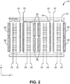
- FIG. 2 illustrates a further example of MEMS sensor where the two proof masses vibrate with zero angular momentum.
- MEMS sensor 200 provides an example of a box-in-frame MEMS sensor having proof masses 202 and 204.
- the MEMS sensor 200 includes an outer proof mass 202 and an inner proof mass 204.
- the center of mass of the outer proof mass 202 and the center of mass of the inner proof mass 204 may be aligned with one another.
- the proof masses may not be as susceptible to errors that may arise in a typical two proof mass sensor, where the two proof masses are on opposite sides of their combined center of mass of the MEMS sensor.
- the outer proof mass 202 and the inner proof mass 204 may vibrate in such a way so that there is zero angular momentum in the sense axis. If vibratory motion occurs for the typical two proof mass sensor with masses on opposite sides of their combined center of mass, during the vibratory motion, one proof mass will move up while the other moves down. This response will be identical to the response of the proof masses to the Coriolis force and therefore the vibratory motion will result in sensor bias.
- the aligning of the centers of mass cause both proof masses to respond to vibratory rotation motion in a way that does not produce output bias and preserves zero angular momentum in the sense axis.
- the inner proof mass 204 responds to vibratory rotation motion, one side of the inner proof 204 mass will move up while the other moves down. Since sensor output is only generated when both sides of the inner proof mass 204 move in the same direction, the vibratory rotation effect will not generate bias.
- the outer proof mass 202 moves similarly to the inner proof mass 204, and thus also does not generate bias.
- the MEMS sensor 200 is equipped with sense electrodes on a substrate that sense the movement of the proof masses 202 and 204.
- the sense electrodes may sense the movement based on capacitance, magnetics, piezoresistivity, and the like. Accordingly, as the drive combs cause the proof masses 202 and 204 to vibrate along the x direction, the sense electrodes are able to sense the motion of the proof masses 202 and 204 with respect to a substrate.
- Connections 205 represent connections to sense electrodes that sense motion in the x direction and connections 206 represent connection to sense electrodes that sense motion in the y direction.
- the connections 205 and 206 provide measurements of motion to a processing unit, where the processing unit uses the measurements to calculate information that can be used for a navigation rate.
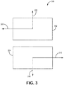
- FIG. 3 is a further diagram illustrating a MEMS sensor 300 having two proof masses that vibrate with zero-angular momentum in the sense axis.
- the MEMS sensor 300 includes a first proof mass 302 and a second proof mass 304.
- the first proof mass 302 and the second proof mass 304 are of equal size and vibrate along respective drive and sense axes.
- the first proof mass 302 is driven along drive axis 306 and vibrates along sense axis 308.
- the second proof mass 304 is driven along drive axis 312 and vibrates along sense axis 308.
- the motion of both the first proof mass 302 and the second proof mass 304 is such that the MEMS sensor 300 has substantially zero angular momentum as the proof masses 302 and 304 move along their respective sense axes 308 and 310.
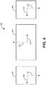
- FIG. 4 is a further diagram illustrating a MEMS sensor 400 having three proof masses that vibrate with substantially zero-angular momentum in the sense axis.
- the MEMS sensor 400 includes a first proof mass 402, a second proof mass 404, and a third proof mass 406.
- the first proof mass 402 and the third proof mass 406 are of equal size and the second proof mass 404 is the same size of the combined sizes of the first proof mass 402 and the third proof mass 406.
- the first proof mass 402 is driven along drive axis 408 and vibrates along sense axis 410.
- the second proof mass 404 is driven along drive axis 412 and vibrates along sense axis 414.
- the third proof mass 406 is driven along drive axis 416 and vibrates along sense axis 418.
- the motion of the second proof mass 404 is such that it balances the motion of the first proof mass 402 and third proof mass 406 such that there is substantially zero angular momentum along the sense axes within the MEMS sensor 300.
- FIG. 5 is a diagram illustrating a MEMS sensor 500 having different lines of symmetry for the arrangement of the outer proof mass 502 and the inner proof mass 504.
- the arrangement illustrated has multiple lines of symmetry.
- the arrangement of proof masses has local symmetry 506, wherein one side of the inner proof mass 504 is symmetric with the most proximate side of the outer proof mass 502.
- each of the proof masses 502 and 504 are symmetrical about two orthogonal axes, axes 508 and 510, that pass through the center of mass.
- a first vertical half of the MEMS sensor 500 is symmetrical with a second vertical half of the MEMS sensor 500 about a vertical axis 508 that passes through the center of mass of the MEMS sensor 500.
- a first horizontal half of MEMS sensor 500 is symmetrical with a second horizontal half of the MEMS sensor 500 about a horizontal axis 510.
- the terms horizontal and vertical are relative terms that indicate that the horizontal axes is orthogonal to the vertical axis, however, the axes are not necessarily horizontal or vertical
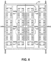
- FIG. 6 illustrates the flexures and anchors 606 of a MEMS sensor 600 that are used to mount the inner proof mass 604 and outer proof mass 602 to a substrate.
- the flexures connect the inner proof mass 604 to the outer proof mass 602 and the flexures also connect the inner proof mass 604 and the outer proof mass 602 to the anchors 606.
- the flexures may be spring type flexures or other type of flexure known to one having skill in the art.
- the flexures may be designed for zero net force on the anchors 606.
- the flexures may be designed for a non-zero net force on the anchors 606.
- directly coupling flexures between proof masses may provide sense mode separation from symmetric translation.
- Example 1 includes a vibratory structure, the vibratory structure comprising: a first proof mass; a second proof mass, wherein the first proof mass and the second proof mass are driven into motion along a first axis, wherein the first proof mass and the second proof mass move in anti-phase along a second axis, wherein the motion of the first proof mass and the second proof mass along the second axis is such that the centers of mass of the first proof mass and the second proof mass move collinearly along a same axis.
- Example 2 includes the vibratory structure of Example 1, wherein the motion of the first proof mass and the second proof mass is such that the total angular momentum of the vibratory structure while moving along the second axis is zero.
- Example 3 includes the vibratory structure of any of Examples 1-2, wherein the resonant frequencies of the motion along the first axis and the second axis are non-degenerate.
- Example 4 includes the vibratory structure of any of Examples 1-3, wherein the structure is a MEMS sensor.
- Example 5 includes the vibratory structure of any of Examples 1-4, wherein the motion of the proof masses in the second axis is determined to produce an output proportional to a measured quantity.
- Example 7 includes the vibratory structure of any of Examples 1-6, further comprising a third proof mass, wherein the first proof mass, the second proof mass, and the third proof mass are driven in a first axis, and the motion of the second proof mass and third proof mass is along the second axis.
- Example 8 includes the vibratory structure of any of Examples 1-7, wherein the first proof mass comprises first proof mass drive combs and/or the second proof mass comprises second proof mass drive combs.
- Example 9 includes the vibratory structure of any of Examples 1-8, further comprising a substrate, wherein a plurality of sense electrodes are mounted on the substrate.
- Example 10 includes the vibratory structure of Example 9, further comprising a plurality of anchors mounted on the substrate, wherein the anchors are coupled to the first proof mass and/or the second proof mass through a plurality of flexures.
- Example 11 includes the vibratory structure of any of Examples 1-10, wherein a first side of the first proof mass is locally symmetrical with a first side of the second proof mass and a second side of the first proof mass is locally symmetrical with a second side of the second proof mass, wherein, the first side of the first proof mass is proximate to the first side of the second proof mass and the second side of the first proof mass is proximate to the second side of the second proof mass.
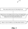
- Example 12 includes a method for suppressing bias errors in a vibratory structure, the method comprising: driving a plurality of proof masses in anti-phase along a first axis; adjusting a frequency of an anti-phase response for motion of plurality of proof masses along a second axis such that the total angular momentum of the vibratory structure while moving in the second axis is zero, wherein the second axis is orthogonal to the first axis; and measuring the motion of the plurality of proof masses along the second axis.
- Example 13 includes the method of Example 12, wherein the motion of the plurality of proof masses is such that the centers of mass for each proof mass in the plurality of proof masses move collinearly along a same axis.
- Example 14 includes the method of any of Examples 12-13, wherein the resonant frequencies of the motion along the first axis and the second axis are non-degenerate.
- Example 15 includes the method of any of Examples 12-14, wherein the vibratory structure is a MEMS sensor.
- Example 16 includes the method of any of Examples 12-15, wherein the motion of the plurality proof masses along the second axis is determined to produce an output proportional to a measured quantity.
- Example 17 includes the method of Example 16, wherein the measured quantity is a measure of rotation rate.
- Example 18 includes a vibratory structure, the vibratory structure comprising: a substrate; a first proof mass; a second proof mass, wherein the first and second proof mass are driven along a first axis, wherein the first and second proof mass move in anti-phase in a second axis, wherein the motion of the two proof masses along the second axis is such that the total angular momentum of the vibratory structure while moving in the second axis is zero; a plurality of anchors mounted on the substrate; a plurality of flexures, wherein the anchors are coupled to the first proof mass and the second proof mass through the plurality of flexures; and a plurality of sense electrodes mounted on the substrate, wherein the plurality of sense electrodes sense motion of the first proof mass and the second proof mass in the second axis.
- Example 19 includes the vibratory structure of Example 18, wherein the motion of the plurality of proof masses is such that the centers of mass for each proof mass in the plurality of proof masses move collinearly along a same axis.
- Example 20 includes the vibratory structure of any of Examples 18-19, wherein the resonant frequencies of the motion along the first axis and the second axis are non-degenerate.
Landscapes
- Engineering & Computer Science (AREA)
- Microelectronics & Electronic Packaging (AREA)
- Physics & Mathematics (AREA)
- General Physics & Mathematics (AREA)
- Radar, Positioning & Navigation (AREA)
- Remote Sensing (AREA)
- Computer Hardware Design (AREA)
- Mechanical Engineering (AREA)
- Health & Medical Sciences (AREA)
- General Health & Medical Sciences (AREA)
- Toxicology (AREA)
- Chemical & Material Sciences (AREA)
- Analytical Chemistry (AREA)
- Gyroscopes (AREA)
Applications Claiming Priority (2)
| Application Number | Priority Date | Filing Date | Title |
|---|---|---|---|
| US201662342132P | 2016-05-26 | 2016-05-26 | |
| US15/466,778 US10696541B2 (en) | 2016-05-26 | 2017-03-22 | Systems and methods for bias suppression in a non-degenerate MEMS sensor |
Publications (2)
| Publication Number | Publication Date |
|---|---|
| EP3249355A1 true EP3249355A1 (de) | 2017-11-29 |
| EP3249355B1 EP3249355B1 (de) | 2020-06-03 |
Family
ID=58410219
Family Applications (1)
| Application Number | Title | Priority Date | Filing Date |
|---|---|---|---|
| EP17162684.9A Active EP3249355B1 (de) | 2016-05-26 | 2017-03-23 | Systeme und verfahren zur bias-unterdrückung in einem nicht degenerierten mems-sensor |
Country Status (2)
| Country | Link |
|---|---|
| US (2) | US10696541B2 (de) |
| EP (1) | EP3249355B1 (de) |
Cited By (1)
| Publication number | Priority date | Publication date | Assignee | Title |
|---|---|---|---|---|
| US20200292313A1 (en) * | 2019-03-11 | 2020-09-17 | Honeywell International Inc. | In-plane non-degenerate coriolis vibratory gyroscope |
Families Citing this family (8)
| Publication number | Priority date | Publication date | Assignee | Title |
|---|---|---|---|---|
| WO2015013828A1 (en) | 2013-08-02 | 2015-02-05 | Motion Engine Inc. | Mems motion sensor and method of manufacturing |
| US20170030788A1 (en) | 2014-04-10 | 2017-02-02 | Motion Engine Inc. | Mems pressure sensor |
| WO2015184531A1 (en) | 2014-06-02 | 2015-12-10 | Motion Engine Inc. | Multi-mass mems motion sensor |
| WO2016090467A1 (en) | 2014-12-09 | 2016-06-16 | Motion Engine Inc. | 3d mems magnetometer and associated methods |
| US10696541B2 (en) * | 2016-05-26 | 2020-06-30 | Honeywell International Inc. | Systems and methods for bias suppression in a non-degenerate MEMS sensor |
| US10466053B2 (en) * | 2017-04-04 | 2019-11-05 | Invensense, Inc. | Out-of-plane sensing gyroscope robust to external acceleration and rotation |
| US12012327B2 (en) | 2020-03-12 | 2024-06-18 | Honeywell International Inc. | Methods for vibration immunity to suppress bias errors in sensor devices |
| CN114858152B (zh) * | 2022-03-30 | 2025-06-17 | 瑞声开泰科技(武汉)有限公司 | 一种mems单轴陀螺 |
Citations (3)
| Publication number | Priority date | Publication date | Assignee | Title |
|---|---|---|---|---|
| US20090064781A1 (en) * | 2007-07-13 | 2009-03-12 | Farrokh Ayazi | Readout method and electronic bandwidth control for a silicon in-plane tuning fork gyroscope |
| US20100313657A1 (en) * | 2009-06-12 | 2010-12-16 | The Regents Of The University Of California | Micromachined tuning fork gyroscopes with ultra-high sensitivity and shock rejection |
| US20160084654A1 (en) * | 2014-09-24 | 2016-03-24 | The Regents Of The University Of California | Fully balanced micro-machined inertial sensor |
Family Cites Families (102)
| Publication number | Priority date | Publication date | Assignee | Title |
|---|---|---|---|---|
| US5349855A (en) | 1992-04-07 | 1994-09-27 | The Charles Stark Draper Laboratory, Inc. | Comb drive micromechanical tuning fork gyro |
| JPH09196682A (ja) | 1996-01-19 | 1997-07-31 | Matsushita Electric Ind Co Ltd | 角速度センサと加速度センサ |
| US6250156B1 (en) | 1996-05-31 | 2001-06-26 | The Regents Of The University Of California | Dual-mass micromachined vibratory rate gyroscope |
| US6578420B1 (en) | 1997-01-28 | 2003-06-17 | Microsensors, Inc. | Multi-axis micro gyro structure |
| WO1999019734A2 (en) * | 1997-10-14 | 1999-04-22 | Irvine Sensors Corporation | Multi-element micro gyro |
| DE19902339A1 (de) | 1998-01-21 | 1999-07-22 | Denso Corp | Verbesserter Aufbau eines Winkelgeschwindigkeitssensors zur Minimierung von Ausgangsrauschen |
| SE9800194D0 (sv) * | 1998-01-23 | 1998-01-23 | Gert Andersson | Anordning för mätning av vinkelhastighet |
| JP3796991B2 (ja) | 1998-12-10 | 2006-07-12 | 株式会社デンソー | 角速度センサ |
| US6289733B1 (en) | 1999-05-12 | 2001-09-18 | Hughes Electronics Corporation | Planar vibratory gyroscopes |
| EP1435828A4 (de) | 2001-09-25 | 2009-11-11 | Nuvasive Inc | System und verfahren zur durchführung von chirurgischen eingriffen und untersuchungen |
| US6651500B2 (en) | 2001-10-03 | 2003-11-25 | Litton Systems, Inc. | Micromachined silicon tuned counterbalanced accelerometer-gyro with quadrature nulling |
| US6862934B2 (en) | 2001-10-05 | 2005-03-08 | The Charles Stark Draper Laboratory, Inc. | Tuning fork gyroscope |
| JP3870895B2 (ja) | 2002-01-10 | 2007-01-24 | 株式会社村田製作所 | 角速度センサ |
| US6877374B2 (en) | 2002-02-06 | 2005-04-12 | Analog Devices, Inc. | Micromachined gyroscope |
| RU2222780C1 (ru) | 2002-07-10 | 2004-01-27 | Открытое акционерное общество Арзамасское научно-производственное предприятие "Темп-Авиа" | Чувствительный элемент микромеханического гироскопа |
| US7040163B2 (en) | 2002-08-12 | 2006-05-09 | The Boeing Company | Isolated planar gyroscope with internal radial sensing and actuation |
| EP1603830B1 (de) | 2003-02-28 | 2016-10-05 | Atlantic Inertial Systems Limited | Beschleunigungsmesser |
| RU2234679C2 (ru) | 2003-03-21 | 2004-08-20 | Открытое акционерное общество Арзамасское научно-производственное предприятие "Темп-Авиа" | Микромеханический датчик угловой скорости |
| US6837107B2 (en) | 2003-04-28 | 2005-01-04 | Analog Devices, Inc. | Micro-machined multi-sensor providing 1-axis of acceleration sensing and 2-axes of angular rate sensing |
| US6848304B2 (en) | 2003-04-28 | 2005-02-01 | Analog Devices, Inc. | Six degree-of-freedom micro-machined multi-sensor |
| DE10360962B4 (de) | 2003-12-23 | 2007-05-31 | Litef Gmbh | Verfahren zur Quadraturbias-Kompensation in einem Corioliskreisel sowie dafür geeigneter Corioliskreisel |
| DE10360963B4 (de) | 2003-12-23 | 2007-05-16 | Litef Gmbh | Verfahren zur Messung von Drehraten/Beschleunigungen unter Verwendung eines Drehraten-Corioliskreisels sowie dafür geeigneter Corioliskreisel |
| RU2251077C1 (ru) | 2004-01-05 | 2005-04-27 | Государственное образовательное учреждение высшего профессионального образования "Таганрогский государственный радиотехнический университет" (ТРТУ) | Интегральный микромеханический гироскоп |
| JP4512636B2 (ja) * | 2004-04-14 | 2010-07-28 | アナログ デバイシス, インコーポレイテッド | 直線的にアレイされたセンサエレメントを有する慣性センサ |
| US7036373B2 (en) | 2004-06-29 | 2006-05-02 | Honeywell International, Inc. | MEMS gyroscope with horizontally oriented drive electrodes |
| US7100446B1 (en) | 2004-07-20 | 2006-09-05 | The Regents Of The University Of California | Distributed-mass micromachined gyroscopes operated with drive-mode bandwidth enhancement |
| DE602004031938D1 (de) | 2004-08-13 | 2011-05-05 | St Microelectronics Srl | Mikroelektromechanische Struktur, insbesondere Beschleunigungssensor, mit verbesserter Unempfindlichkeit gegenüber thermischen und mechanischen Spannungen |
| EP1645847B1 (de) | 2004-10-08 | 2014-07-02 | STMicroelectronics Srl | Mikro-elektromechanische Vorrichtung mit Temperaturkompensation und Verfahren zur Temperaturkompensation in einer mikro-elektromechanischen Vorrichtung |
| US7832271B2 (en) | 2005-05-24 | 2010-11-16 | Japan Aerospace Exploration Agency | Gyroscope |
| FR2888318B1 (fr) | 2005-07-05 | 2007-09-14 | Thales Sa | Capteur gyrometrique micro-usine realisant une mesure differentielle du mouvement des masses vibrantes |
| US7562573B2 (en) | 2005-07-21 | 2009-07-21 | Evigia Systems, Inc. | Integrated sensor and circuitry and process therefor |
| JP4702942B2 (ja) | 2005-10-14 | 2011-06-15 | Necトーキン株式会社 | 振動ジャイロ用素子及び振動ジャイロ |
| US8113050B2 (en) | 2006-01-25 | 2012-02-14 | The Regents Of The University Of California | Robust six degree-of-freedom micromachined gyroscope with anti-phase drive scheme and method of operation of the same |
| JP4687577B2 (ja) | 2006-06-16 | 2011-05-25 | ソニー株式会社 | 慣性センサ |
| JP5030135B2 (ja) | 2006-07-18 | 2012-09-19 | Necトーキン株式会社 | 圧電単結晶振動子および圧電振動ジャイロ |
| JP2008145325A (ja) | 2006-12-12 | 2008-06-26 | Nec Tokin Corp | 振動ジャイロ |
| JP4343965B2 (ja) | 2007-02-15 | 2009-10-14 | Okiセミコンダクタ株式会社 | 慣性センサ |
| US8006557B2 (en) | 2007-05-16 | 2011-08-30 | Intellisense Software Corporation | Multi-axis sensor |
| DE102007030119A1 (de) | 2007-06-29 | 2009-01-02 | Litef Gmbh | Corioliskreisel |
| DE102007030120B4 (de) | 2007-06-29 | 2010-04-08 | Litef Gmbh | Drehratensensor |
| JP2009192403A (ja) | 2008-02-15 | 2009-08-27 | Nec Tokin Corp | 角速度および加速度検出装置 |
| WO2009107573A1 (ja) | 2008-02-25 | 2009-09-03 | アルプス電気株式会社 | 角速度センサ |
| CN101261126B (zh) | 2008-04-10 | 2010-06-02 | 上海交通大学 | 微固体模态陀螺 |
| DE102008002748A1 (de) | 2008-06-27 | 2009-12-31 | Sensordynamics Ag | Mikro-Gyroskop |
| US7912664B2 (en) | 2008-09-11 | 2011-03-22 | Northrop Grumman Guidance And Electronics Company, Inc. | Self calibrating gyroscope system |
| CN101363731B (zh) | 2008-09-25 | 2011-01-26 | 中国人民解放军国防科学技术大学 | 基于剪应力检测的石英微机械陀螺及其制作方法 |
| EP2177875A3 (de) | 2008-10-14 | 2013-04-24 | Watson Industries, Inc. | Schwingendes Strukturgyroskop mit Quadratursteuerung |
| JP2010096695A (ja) | 2008-10-20 | 2010-04-30 | Nec Tokin Corp | 振動ジャイロ |
| US20100095768A1 (en) | 2008-10-20 | 2010-04-22 | Custom Sensors & Technologies, Inc. | Micromachined torsional gyroscope with anti-phase linear sense transduction |
| DE502008002421D1 (de) | 2008-11-11 | 2011-03-03 | Fraunhofer Ges Forschung | Mikromechanischer Coriolis-Drehratensensor |
| IT1391972B1 (it) | 2008-11-26 | 2012-02-02 | St Microelectronics Rousset | Giroscopio microelettromeccanico con movimento di azionamento rotatorio e migliorate caratteristiche elettriche |
| IT1391973B1 (it) | 2008-11-26 | 2012-02-02 | St Microelectronics Rousset | Giroscopio microelettromeccanico mono o biassiale con aumentata sensibilita' al rilevamento di velocita' angolari |
| DE102009001248B4 (de) | 2009-02-27 | 2020-12-17 | Hanking Electronics, Ltd. | MEMS-Gyroskop zur Ermittlung von Rotationsbewegungen um eine x-, y- oder z-Achse |
| DE102009001244A1 (de) | 2009-02-27 | 2010-09-02 | Sensordynamics Ag | Mikro-Gyroskop zur Ermittlung von Rotationsbewegungen um eine x-, y- oder z-Achse |
| US8256290B2 (en) | 2009-03-17 | 2012-09-04 | Minyao Mao | Tri-axis angular rate sensor |
| DE102009001922A1 (de) | 2009-03-26 | 2010-09-30 | Sensordynamics Ag | Mikro-Gyroskop zur Ermittlung von Rotationsbewegungen um drei senkrecht aufeinanderstehende Raumachsen x, y und z |
| US8272266B2 (en) | 2009-04-09 | 2012-09-25 | Hewlett-Packard Development Company, L.P. | Gyroscopes using surface electrodes |
| IT1394007B1 (it) | 2009-05-11 | 2012-05-17 | St Microelectronics Rousset | Struttura microelettromeccanica con reiezione migliorata di disturbi di accelerazione |
| FR2945621B1 (fr) | 2009-05-15 | 2011-08-26 | Commissariat Energie Atomique | Structure de couplage pour gyrometre resonnant |
| WO2010138717A1 (en) | 2009-05-27 | 2010-12-02 | King Abdullah University Of Science And Technology | Mems mass spring damper systems using an out-of-plane suspension scheme |
| US9074890B2 (en) | 2009-09-09 | 2015-07-07 | Continental Teves Ag & Co Ohg | Double-axle, shock-resistant rotation rate sensor with linear and rotary seismic elements |
| US8534127B2 (en) | 2009-09-11 | 2013-09-17 | Invensense, Inc. | Extension-mode angular velocity sensor |
| US8549915B2 (en) | 2009-10-23 | 2013-10-08 | The Regents Of The University Of California | Micromachined gyroscopes with 2-DOF sense modes allowing interchangeable robust and precision operation |
| RU2423668C1 (ru) | 2009-12-01 | 2011-07-10 | Государственное образовательное учреждение высшего профессионального образования Московский государственный институт электронной техники (технический университет) (МИЭТ) | Чувствительный элемент микромеханического гироскопа |
| ITTO20091042A1 (it) | 2009-12-24 | 2011-06-25 | St Microelectronics Srl | Giroscopio integrato microelettromeccanico con migliorata struttura di azionamento |
| DE102010028005A1 (de) | 2010-04-20 | 2011-10-20 | Sensordynamics Ag | Mikro-Gyroskop zur Ermittlung von Bewegungen |
| US8516887B2 (en) | 2010-04-30 | 2013-08-27 | Qualcomm Mems Technologies, Inc. | Micromachined piezoelectric z-axis gyroscope |
| EP2584312B1 (de) * | 2010-06-16 | 2020-02-05 | Toyota Jidosha Kabushiki Kaisha | Verbundsensor |
| US8317104B2 (en) | 2010-08-05 | 2012-11-27 | Hand Held Products, Inc. | Image engine with integrated circuit structure for indicia reading terminal |
| US8616056B2 (en) | 2010-11-05 | 2013-12-31 | Analog Devices, Inc. | BAW gyroscope with bottom electrode |
| EP2646773B1 (de) | 2010-12-01 | 2015-06-24 | Analog Devices, Inc. | Vorrichtung und verfahren zur verankerung von elektroden in mems-vorrichtungen |
| CN201945318U (zh) | 2011-02-14 | 2011-08-24 | 孙博华 | 心跳型单结构三轴微机电陀螺仪 |
| JP2012193971A (ja) | 2011-03-15 | 2012-10-11 | Seiko Epson Corp | センサーモジュール、センサーデバイス、センサーデバイスの製造方法及び電子機器 |
| JP5822177B2 (ja) | 2011-05-20 | 2015-11-24 | セイコーエプソン株式会社 | ジャイロセンサー、電子機器 |
| CN102305626B (zh) | 2011-07-07 | 2013-04-17 | 西北工业大学 | 一种新型mems离心式陀螺 |
| CN102278982B (zh) | 2011-07-13 | 2013-07-24 | 中国人民解放军国防科学技术大学 | 四质量块硅微机械陀螺耦合误差的抑制方法 |
| ITTO20110806A1 (it) | 2011-09-12 | 2013-03-13 | St Microelectronics Srl | Dispositivo microelettromeccanico integrante un giroscopio e un accelerometro |
| US8991247B2 (en) | 2011-10-21 | 2015-03-31 | The Regents Of The University Of California | High range digital angular rate sensor based on frequency modulation |
| FR2983574B1 (fr) | 2011-12-06 | 2014-01-10 | Sagem Defense Securite | Capteur angulaire inertiel de type mems equilibre et procede d'equilibrage d'un tel capteur |
| EP2607849A1 (de) | 2011-12-22 | 2013-06-26 | Tronics Microsystems S.A. | Mehrachsiger mikroelektronischer Trägheitssensor |
| DE102011057081A1 (de) | 2011-12-28 | 2013-07-04 | Maxim Integrated Products, Inc. | Mikro-Drehratensensor und Verfahren zum Betreiben eines Mikro-Drehratensensors |
| CN103213939B (zh) | 2012-01-19 | 2016-01-20 | 北京自动化控制设备研究所 | 一种四质量块硅微机电陀螺结构的加工方法 |
| WO2013108804A1 (ja) | 2012-01-19 | 2013-07-25 | 株式会社村田製作所 | 振動ジャイロ |
| US9759563B2 (en) | 2012-01-31 | 2017-09-12 | Nxp Usa, Inc. | Vibration robust x-axis ring gyro transducer |
| CN103245340B (zh) | 2012-02-01 | 2016-07-13 | 苏州敏芯微电子技术股份有限公司 | 一种单芯片三轴陀螺仪 |
| CN102636162B (zh) | 2012-03-26 | 2015-02-11 | 北京航天时代光电科技有限公司 | 一种三轴微机械陀螺仪 |
| US9212908B2 (en) | 2012-04-26 | 2015-12-15 | Analog Devices, Inc. | MEMS gyroscopes with reduced errors |
| CN103575263B (zh) | 2012-07-19 | 2017-03-29 | 水木智芯科技(北京)有限公司 | 四质量块全解耦电容式单轴微机械陀螺仪 |
| CN202793402U (zh) | 2012-07-19 | 2013-03-13 | 水木智芯科技(北京)有限公司 | 四质量块全解耦电容式单轴微机械陀螺仪 |
| US9006642B2 (en) | 2012-08-21 | 2015-04-14 | Delta Electronics, Inc. | Focus adjustable apparatus |
| EP2746724B1 (de) | 2012-12-20 | 2017-02-22 | Tronics Microsystems S.A. | Mikromechanisches Gyroskop |
| US9194704B2 (en) | 2013-03-13 | 2015-11-24 | Freescale Semiconductor, Inc. | Angular rate sensor having multiple axis sensing capability |
| FR3005160B1 (fr) | 2013-04-29 | 2016-02-12 | Sagem Defense Securite | Capteur angulaire inertiel de type mems equilibre et procede d'equilibrage d'un tel capteur |
| FI126071B (en) * | 2014-01-28 | 2016-06-15 | Murata Manufacturing Co | Improved gyroscope design and gyroscope |
| US9995583B2 (en) * | 2014-05-15 | 2018-06-12 | Hanking Electronics, Ltd. | Systems and methods for MEMS gyroscope shock robustness |
| FR3022996B1 (fr) | 2014-06-27 | 2017-12-01 | Thales Sa | Capteur inertiel angulaire mems fonctionnant en mode diapason |
| ITUB20159197A1 (it) | 2015-12-29 | 2017-06-29 | St Microelectronics Srl | Giroscopio microelettromeccanico con reiezione di disturbi e metodo di rilevamento di una velocita' angolare |
| US10371521B2 (en) | 2016-05-26 | 2019-08-06 | Honeywell International Inc. | Systems and methods for a four-mass vibrating MEMS structure |
| US10696541B2 (en) | 2016-05-26 | 2020-06-30 | Honeywell International Inc. | Systems and methods for bias suppression in a non-degenerate MEMS sensor |
| US10794702B2 (en) | 2017-12-13 | 2020-10-06 | Invensense, Inc. | On-chip gap measurement |
| US11118907B2 (en) | 2018-09-21 | 2021-09-14 | Invensense, Inc. | Drive and sense balanced, fully-coupled 3-axis gyroscope |
| US20200292313A1 (en) * | 2019-03-11 | 2020-09-17 | Honeywell International Inc. | In-plane non-degenerate coriolis vibratory gyroscope |
-
2017
- 2017-03-22 US US15/466,778 patent/US10696541B2/en active Active
- 2017-03-23 EP EP17162684.9A patent/EP3249355B1/de active Active
-
2020
- 2020-06-30 US US16/917,292 patent/US11390517B2/en active Active
Patent Citations (3)
| Publication number | Priority date | Publication date | Assignee | Title |
|---|---|---|---|---|
| US20090064781A1 (en) * | 2007-07-13 | 2009-03-12 | Farrokh Ayazi | Readout method and electronic bandwidth control for a silicon in-plane tuning fork gyroscope |
| US20100313657A1 (en) * | 2009-06-12 | 2010-12-16 | The Regents Of The University Of California | Micromachined tuning fork gyroscopes with ultra-high sensitivity and shock rejection |
| US20160084654A1 (en) * | 2014-09-24 | 2016-03-24 | The Regents Of The University Of California | Fully balanced micro-machined inertial sensor |
Cited By (1)
| Publication number | Priority date | Publication date | Assignee | Title |
|---|---|---|---|---|
| US20200292313A1 (en) * | 2019-03-11 | 2020-09-17 | Honeywell International Inc. | In-plane non-degenerate coriolis vibratory gyroscope |
Also Published As
| Publication number | Publication date |
|---|---|
| EP3249355B1 (de) | 2020-06-03 |
| US20180118557A1 (en) | 2018-05-03 |
| US10696541B2 (en) | 2020-06-30 |
| US20200346920A1 (en) | 2020-11-05 |
| US11390517B2 (en) | 2022-07-19 |
Similar Documents
| Publication | Publication Date | Title |
|---|---|---|
| US11390517B2 (en) | Systems and methods for bias suppression in a non-degenerate MEMS sensor | |
| EP2977722B1 (de) | Schwungmasse-gyroskopsystem und verfahren | |
| US7971483B2 (en) | Systems and methods for acceleration and rotational determination from an out-of-plane MEMS device | |
| EP2017576B1 (de) | Kombiniertes System mit Beschleunigungsmesser und Gyroskop | |
| EP3428576B1 (de) | Winkelgeschwindigkeitssensor mit struktur zur unterdrückung von gleichphasiger bewegung | |
| JP5554930B2 (ja) | 自己較正を備えた容量性バルク弾性波ディスク・ジャイロスコープ | |
| US9315376B2 (en) | Planar structure for a triaxial gyrometer | |
| CN104296746B (zh) | 一种新型微型惯性测量单元组合 | |
| EP3751232A1 (de) | Nicht-degeneriertes coriolis-vibrationsgyroskop auf gleicher ebene | |
| EP3249356A1 (de) | Systeme und verfahren für eine vibrierende viermassen-mems-struktur | |
| EP1752735B1 (de) | Auslöschung der Bias-fehlern eines Schwingkreisels mittels Modenumkehr | |
| US8561466B2 (en) | Vibratory gyro bias error cancellation using mode reversal | |
| JP3307907B2 (ja) | マイクロジャイロスコープ | |
| EP3495772B1 (de) | Schwingungsmassen-gyroskopsystem | |
| Shah et al. | Design and analysis of a single-structure three-axis MEMS gyroscope with improved coupling spring | |
| EP3798642B1 (de) | Coriolis-schwingungsbeschleunigungsmesssystem | |
| JP2016040550A (ja) | 物理量センサー、電子機器 | |
| CN105444748B (zh) | 抗干扰的陀螺仪 | |
| Liu et al. | Design and evaluation of a vibration sensor for measurement-while-drilling | |
| Shah et al. | Research Article Modal Analysis of a Single-Structure Multiaxis MEMS Gyroscope | |
| JP2006125917A (ja) | 角速度センサ | |
| CN105444748A (zh) | 抗干扰的陀螺仪 |
Legal Events
| Date | Code | Title | Description |
|---|---|---|---|
| PUAI | Public reference made under article 153(3) epc to a published international application that has entered the european phase |
Free format text: ORIGINAL CODE: 0009012 |
|
| STAA | Information on the status of an ep patent application or granted ep patent |
Free format text: STATUS: REQUEST FOR EXAMINATION WAS MADE |
|
| 17P | Request for examination filed |
Effective date: 20170323 |
|
| AK | Designated contracting states |
Kind code of ref document: A1 Designated state(s): AL AT BE BG CH CY CZ DE DK EE ES FI FR GB GR HR HU IE IS IT LI LT LU LV MC MK MT NL NO PL PT RO RS SE SI SK SM TR |
|
| AX | Request for extension of the european patent |
Extension state: BA ME |
|
| STAA | Information on the status of an ep patent application or granted ep patent |
Free format text: STATUS: EXAMINATION IS IN PROGRESS |
|
| 17Q | First examination report despatched |
Effective date: 20181114 |
|
| GRAP | Despatch of communication of intention to grant a patent |
Free format text: ORIGINAL CODE: EPIDOSNIGR1 |
|
| STAA | Information on the status of an ep patent application or granted ep patent |
Free format text: STATUS: GRANT OF PATENT IS INTENDED |
|
| RIN1 | Information on inventor provided before grant (corrected) |
Inventor name: ENDEAN, DANIEL Inventor name: REINKE, JOHN |
|
| INTG | Intention to grant announced |
Effective date: 20200204 |
|
| GRAS | Grant fee paid |
Free format text: ORIGINAL CODE: EPIDOSNIGR3 |
|
| GRAA | (expected) grant |
Free format text: ORIGINAL CODE: 0009210 |
|
| STAA | Information on the status of an ep patent application or granted ep patent |
Free format text: STATUS: THE PATENT HAS BEEN GRANTED |
|
| AK | Designated contracting states |
Kind code of ref document: B1 Designated state(s): AL AT BE BG CH CY CZ DE DK EE ES FI FR GB GR HR HU IE IS IT LI LT LU LV MC MK MT NL NO PL PT RO RS SE SI SK SM TR |
|
| REG | Reference to a national code |
Ref country code: GB Ref legal event code: FG4D |
|
| REG | Reference to a national code |
Ref country code: CH Ref legal event code: EP Ref country code: AT Ref legal event code: REF Ref document number: 1277463 Country of ref document: AT Kind code of ref document: T Effective date: 20200615 |
|
| REG | Reference to a national code |
Ref country code: DE Ref legal event code: R096 Ref document number: 602017017515 Country of ref document: DE |
|
| REG | Reference to a national code |
Ref country code: LT Ref legal event code: MG4D |
|
| PG25 | Lapsed in a contracting state [announced via postgrant information from national office to epo] |
Ref country code: SE Free format text: LAPSE BECAUSE OF FAILURE TO SUBMIT A TRANSLATION OF THE DESCRIPTION OR TO PAY THE FEE WITHIN THE PRESCRIBED TIME-LIMIT Effective date: 20200603 Ref country code: NO Free format text: LAPSE BECAUSE OF FAILURE TO SUBMIT A TRANSLATION OF THE DESCRIPTION OR TO PAY THE FEE WITHIN THE PRESCRIBED TIME-LIMIT Effective date: 20200903 Ref country code: FI Free format text: LAPSE BECAUSE OF FAILURE TO SUBMIT A TRANSLATION OF THE DESCRIPTION OR TO PAY THE FEE WITHIN THE PRESCRIBED TIME-LIMIT Effective date: 20200603 Ref country code: GR Free format text: LAPSE BECAUSE OF FAILURE TO SUBMIT A TRANSLATION OF THE DESCRIPTION OR TO PAY THE FEE WITHIN THE PRESCRIBED TIME-LIMIT Effective date: 20200904 Ref country code: LT Free format text: LAPSE BECAUSE OF FAILURE TO SUBMIT A TRANSLATION OF THE DESCRIPTION OR TO PAY THE FEE WITHIN THE PRESCRIBED TIME-LIMIT Effective date: 20200603 |
|
| REG | Reference to a national code |
Ref country code: NL Ref legal event code: MP Effective date: 20200603 |
|
| PG25 | Lapsed in a contracting state [announced via postgrant information from national office to epo] |
Ref country code: LV Free format text: LAPSE BECAUSE OF FAILURE TO SUBMIT A TRANSLATION OF THE DESCRIPTION OR TO PAY THE FEE WITHIN THE PRESCRIBED TIME-LIMIT Effective date: 20200603 Ref country code: RS Free format text: LAPSE BECAUSE OF FAILURE TO SUBMIT A TRANSLATION OF THE DESCRIPTION OR TO PAY THE FEE WITHIN THE PRESCRIBED TIME-LIMIT Effective date: 20200603 Ref country code: BG Free format text: LAPSE BECAUSE OF FAILURE TO SUBMIT A TRANSLATION OF THE DESCRIPTION OR TO PAY THE FEE WITHIN THE PRESCRIBED TIME-LIMIT Effective date: 20200903 Ref country code: HR Free format text: LAPSE BECAUSE OF FAILURE TO SUBMIT A TRANSLATION OF THE DESCRIPTION OR TO PAY THE FEE WITHIN THE PRESCRIBED TIME-LIMIT Effective date: 20200603 |
|
| REG | Reference to a national code |
Ref country code: AT Ref legal event code: MK05 Ref document number: 1277463 Country of ref document: AT Kind code of ref document: T Effective date: 20200603 |
|
| PG25 | Lapsed in a contracting state [announced via postgrant information from national office to epo] |
Ref country code: NL Free format text: LAPSE BECAUSE OF FAILURE TO SUBMIT A TRANSLATION OF THE DESCRIPTION OR TO PAY THE FEE WITHIN THE PRESCRIBED TIME-LIMIT Effective date: 20200603 Ref country code: AL Free format text: LAPSE BECAUSE OF FAILURE TO SUBMIT A TRANSLATION OF THE DESCRIPTION OR TO PAY THE FEE WITHIN THE PRESCRIBED TIME-LIMIT Effective date: 20200603 |
|
| PG25 | Lapsed in a contracting state [announced via postgrant information from national office to epo] |
Ref country code: IT Free format text: LAPSE BECAUSE OF FAILURE TO SUBMIT A TRANSLATION OF THE DESCRIPTION OR TO PAY THE FEE WITHIN THE PRESCRIBED TIME-LIMIT Effective date: 20200603 Ref country code: RO Free format text: LAPSE BECAUSE OF FAILURE TO SUBMIT A TRANSLATION OF THE DESCRIPTION OR TO PAY THE FEE WITHIN THE PRESCRIBED TIME-LIMIT Effective date: 20200603 Ref country code: PT Free format text: LAPSE BECAUSE OF FAILURE TO SUBMIT A TRANSLATION OF THE DESCRIPTION OR TO PAY THE FEE WITHIN THE PRESCRIBED TIME-LIMIT Effective date: 20201006 Ref country code: CZ Free format text: LAPSE BECAUSE OF FAILURE TO SUBMIT A TRANSLATION OF THE DESCRIPTION OR TO PAY THE FEE WITHIN THE PRESCRIBED TIME-LIMIT Effective date: 20200603 Ref country code: SM Free format text: LAPSE BECAUSE OF FAILURE TO SUBMIT A TRANSLATION OF THE DESCRIPTION OR TO PAY THE FEE WITHIN THE PRESCRIBED TIME-LIMIT Effective date: 20200603 Ref country code: EE Free format text: LAPSE BECAUSE OF FAILURE TO SUBMIT A TRANSLATION OF THE DESCRIPTION OR TO PAY THE FEE WITHIN THE PRESCRIBED TIME-LIMIT Effective date: 20200603 Ref country code: AT Free format text: LAPSE BECAUSE OF FAILURE TO SUBMIT A TRANSLATION OF THE DESCRIPTION OR TO PAY THE FEE WITHIN THE PRESCRIBED TIME-LIMIT Effective date: 20200603 Ref country code: ES Free format text: LAPSE BECAUSE OF FAILURE TO SUBMIT A TRANSLATION OF THE DESCRIPTION OR TO PAY THE FEE WITHIN THE PRESCRIBED TIME-LIMIT Effective date: 20200603 |
|
| PG25 | Lapsed in a contracting state [announced via postgrant information from national office to epo] |
Ref country code: SK Free format text: LAPSE BECAUSE OF FAILURE TO SUBMIT A TRANSLATION OF THE DESCRIPTION OR TO PAY THE FEE WITHIN THE PRESCRIBED TIME-LIMIT Effective date: 20200603 Ref country code: PL Free format text: LAPSE BECAUSE OF FAILURE TO SUBMIT A TRANSLATION OF THE DESCRIPTION OR TO PAY THE FEE WITHIN THE PRESCRIBED TIME-LIMIT Effective date: 20200603 Ref country code: IS Free format text: LAPSE BECAUSE OF FAILURE TO SUBMIT A TRANSLATION OF THE DESCRIPTION OR TO PAY THE FEE WITHIN THE PRESCRIBED TIME-LIMIT Effective date: 20201003 |
|
| REG | Reference to a national code |
Ref country code: DE Ref legal event code: R097 Ref document number: 602017017515 Country of ref document: DE |
|
| PLBE | No opposition filed within time limit |
Free format text: ORIGINAL CODE: 0009261 |
|
| STAA | Information on the status of an ep patent application or granted ep patent |
Free format text: STATUS: NO OPPOSITION FILED WITHIN TIME LIMIT |
|
| PG25 | Lapsed in a contracting state [announced via postgrant information from national office to epo] |
Ref country code: DK Free format text: LAPSE BECAUSE OF FAILURE TO SUBMIT A TRANSLATION OF THE DESCRIPTION OR TO PAY THE FEE WITHIN THE PRESCRIBED TIME-LIMIT Effective date: 20200603 |
|
| 26N | No opposition filed |
Effective date: 20210304 |
|
| PG25 | Lapsed in a contracting state [announced via postgrant information from national office to epo] |
Ref country code: SI Free format text: LAPSE BECAUSE OF FAILURE TO SUBMIT A TRANSLATION OF THE DESCRIPTION OR TO PAY THE FEE WITHIN THE PRESCRIBED TIME-LIMIT Effective date: 20200603 |
|
| PG25 | Lapsed in a contracting state [announced via postgrant information from national office to epo] |
Ref country code: MC Free format text: LAPSE BECAUSE OF FAILURE TO SUBMIT A TRANSLATION OF THE DESCRIPTION OR TO PAY THE FEE WITHIN THE PRESCRIBED TIME-LIMIT Effective date: 20200603 |
|
| REG | Reference to a national code |
Ref country code: CH Ref legal event code: PL |
|
| REG | Reference to a national code |
Ref country code: BE Ref legal event code: MM Effective date: 20210331 |
|
| PG25 | Lapsed in a contracting state [announced via postgrant information from national office to epo] |
Ref country code: CH Free format text: LAPSE BECAUSE OF NON-PAYMENT OF DUE FEES Effective date: 20210331 Ref country code: LU Free format text: LAPSE BECAUSE OF NON-PAYMENT OF DUE FEES Effective date: 20210323 Ref country code: LI Free format text: LAPSE BECAUSE OF NON-PAYMENT OF DUE FEES Effective date: 20210331 Ref country code: IE Free format text: LAPSE BECAUSE OF NON-PAYMENT OF DUE FEES Effective date: 20210323 Ref country code: FR Free format text: LAPSE BECAUSE OF NON-PAYMENT OF DUE FEES Effective date: 20210331 |
|
| PG25 | Lapsed in a contracting state [announced via postgrant information from national office to epo] |
Ref country code: BE Free format text: LAPSE BECAUSE OF NON-PAYMENT OF DUE FEES Effective date: 20210331 |
|
| PG25 | Lapsed in a contracting state [announced via postgrant information from national office to epo] |
Ref country code: HU Free format text: LAPSE BECAUSE OF FAILURE TO SUBMIT A TRANSLATION OF THE DESCRIPTION OR TO PAY THE FEE WITHIN THE PRESCRIBED TIME-LIMIT; INVALID AB INITIO Effective date: 20170323 |
|
| PG25 | Lapsed in a contracting state [announced via postgrant information from national office to epo] |
Ref country code: CY Free format text: LAPSE BECAUSE OF FAILURE TO SUBMIT A TRANSLATION OF THE DESCRIPTION OR TO PAY THE FEE WITHIN THE PRESCRIBED TIME-LIMIT Effective date: 20200603 |
|
| P01 | Opt-out of the competence of the unified patent court (upc) registered |
Effective date: 20230525 |
|
| PG25 | Lapsed in a contracting state [announced via postgrant information from national office to epo] |
Ref country code: MK Free format text: LAPSE BECAUSE OF FAILURE TO SUBMIT A TRANSLATION OF THE DESCRIPTION OR TO PAY THE FEE WITHIN THE PRESCRIBED TIME-LIMIT Effective date: 20200603 |
|
| PG25 | Lapsed in a contracting state [announced via postgrant information from national office to epo] |
Ref country code: TR Free format text: LAPSE BECAUSE OF FAILURE TO SUBMIT A TRANSLATION OF THE DESCRIPTION OR TO PAY THE FEE WITHIN THE PRESCRIBED TIME-LIMIT Effective date: 20200603 |
|
| PG25 | Lapsed in a contracting state [announced via postgrant information from national office to epo] |
Ref country code: MT Free format text: LAPSE BECAUSE OF FAILURE TO SUBMIT A TRANSLATION OF THE DESCRIPTION OR TO PAY THE FEE WITHIN THE PRESCRIBED TIME-LIMIT Effective date: 20200603 |
|
| PGFP | Annual fee paid to national office [announced via postgrant information from national office to epo] |
Ref country code: GB Payment date: 20260319 Year of fee payment: 10 |
|
| PGFP | Annual fee paid to national office [announced via postgrant information from national office to epo] |
Ref country code: DE Payment date: 20260320 Year of fee payment: 10 |