EP3254641B1 - Procédé de production d'un appareil de durcissement par rayonnement, d'une fixation et d'un appareil de production de restauration dentaire - Google Patents
Procédé de production d'un appareil de durcissement par rayonnement, d'une fixation et d'un appareil de production de restauration dentaire Download PDFInfo
- Publication number
- EP3254641B1 EP3254641B1 EP16173538.6A EP16173538A EP3254641B1 EP 3254641 B1 EP3254641 B1 EP 3254641B1 EP 16173538 A EP16173538 A EP 16173538A EP 3254641 B1 EP3254641 B1 EP 3254641B1
- Authority
- EP
- European Patent Office
- Prior art keywords
- attachment
- dental restoration
- add
- restoration material
- radiation
- Prior art date
- Legal status (The legal status is an assumption and is not a legal conclusion. Google has not performed a legal analysis and makes no representation as to the accuracy of the status listed.)
- Active
Links
Images


Classifications
-
- A—HUMAN NECESSITIES
- A61—MEDICAL OR VETERINARY SCIENCE; HYGIENE
- A61C—DENTISTRY; APPARATUS OR METHODS FOR ORAL OR DENTAL HYGIENE
- A61C19/00—Dental auxiliary appliances
- A61C19/003—Apparatus for curing resins by radiation
- A61C19/004—Hand-held apparatus, e.g. guns
-
- A—HUMAN NECESSITIES
- A61—MEDICAL OR VETERINARY SCIENCE; HYGIENE
- A61C—DENTISTRY; APPARATUS OR METHODS FOR ORAL OR DENTAL HYGIENE
- A61C3/00—Dental tools or instruments
-
- A—HUMAN NECESSITIES
- A61—MEDICAL OR VETERINARY SCIENCE; HYGIENE
- A61C—DENTISTRY; APPARATUS OR METHODS FOR ORAL OR DENTAL HYGIENE
- A61C5/00—Filling or capping teeth
- A61C5/70—Tooth crowns; Making thereof
- A61C5/77—Methods or devices for making crowns
-
- A—HUMAN NECESSITIES
- A61—MEDICAL OR VETERINARY SCIENCE; HYGIENE
- A61C—DENTISTRY; APPARATUS OR METHODS FOR ORAL OR DENTAL HYGIENE
- A61C13/00—Dental prostheses; Making same
- A61C13/0001—In-situ dentures; Trial or temporary dentures
-
- A—HUMAN NECESSITIES
- A61—MEDICAL OR VETERINARY SCIENCE; HYGIENE
- A61C—DENTISTRY; APPARATUS OR METHODS FOR ORAL OR DENTAL HYGIENE
- A61C5/00—Filling or capping teeth
- A61C5/80—Dental aids fixed to teeth during treatment, e.g. tooth clamps
- A61C5/85—Filling bands, e.g. matrix bands; Manipulating tools therefor
Definitions
- the invention relates to a method for producing an attachment (24) or attachment of a radiation curing device according to the preamble of claim 1, an attachment or attachment for a radiation device according to the preamble of claim 12 or a dental restoration product device according to the preamble of claim 13, to create a Dental restoration production device according to the preamble of claim 1, an attachment or attachment according to the preamble of claim 12 and a dental restoration production device according to the preamble of claim 13.
- This protective cover is designed as a single-use product and should be discarded after use.
- the dentist will clean the protective cover before using it again, although there is no guarantee that this will take place or that the cleaning will be perfect.
- the end of the light guide rod is typically made of glass and is therefore significantly harder than the still soft dental restoration material. If the light guide rod is accidentally pressed against the still soft dental restoration material, it will inadvertently deform it, so that the desired tooth surface in the area of the occlusal surface - or possibly also in the distal area of this, from which direction the end of the light guide rod is guided to the dental restoration material - no longer has the desired design that is exactly adapted to the antagonist of the tooth to be treated.
- a method and a device for placing a light-activated dental restoration material in a cavity preparation or between adjacent teeth and for polymerizing the dental restoration material there are known.
- the device there has a radiation hardening device to which a working element is detachably connected and held against a dental restoration to be produced in order to maintain its shape during hardening.
- the production of the dental restoration there is quite time-consuming.
- the pamphlet DE 102 34 994 A1 discloses an apparatus for applying a veneer to a tooth.
- a carrier element made of silicone plastic is provided there, which can be used together with a light curing device if necessary.
- dental restoration parts are typically computer-aided, that is to say implemented by CAD / CAM.
- the design phase is ongoing after the intraoral scan in the virtual area on the computer, and after the external shape of the dental restoration part has been determined, the way in which the dental restoration part is to be produced is basically up to the user.
- the CAD data allow conversion to milling data in STL format, or the implementation of a positive model. This is then cast and, after the muffle has hardened, melted out of it. In this way, a mold cavity is created for providing a dental restoration part made of ceramic or composite.
- the shape of the antagonist is of course also taken into account, but gnathological aspects can also be incorporated by taking the so-called functional impression.
- the data which are already available are now used in a surprisingly simple manner for the production of a light curing device attachment or attachment made of transparent material.
- this attachment or approach forms a negative form for the dental restoration material.
- the attachment or approach thus forms, as it were, a stamp for defining the shape of the dental restoration part, which is used while the dental restoration material is still soft.
- the attachment or attachment is made of silicone or any other transparent material that does not adhere to the dental restoration material.
- the light guide rod is kept in contact with the dental restoration material during the entire light curing time, which can be between 5 and 30 seconds, for example. During this time, the dental restoration material hardens from an almost liquid aggregate state to a very solid aggregate state.
- the invention results in a further particular advantage with regard to the light curing time.
- the direct contact between the surface of the dental restoration material and the attachment or attachment eliminates the need to send the radiation used for curing, which comes from the light guide rod, through an air gap.
- the refractive index of the attachment or attachment can now be selected so that it lies between that of the glass of the light guide rod and that of the dental restoration material in the soft state.
- the proportion of radiation reduced at the transition surfaces can thus be reduced significantly, for example by a power of ten, because this prevents an optical transition between materials with a high and a low refractive index having to be created twice, with the typical losses due to reflection or Refraction at the transition surface.
- the attachment or attachment according to the invention from the suitable material such as silicone can be produced in an advantageous embodiment, for example, by 3D printing or by milling or by casting.
- the silicone attachment then forms the negative form for the desired tooth contour. This can be derived in a manner known per se from the contour detected by means of an interdental scanner and consists of a negative shape for the surface of the tooth after the dental restoration part has been applied.
- the attachment or attachment is a disposable part which, however, is patient-specific, so that reuse is impossible.
- the smooth surface of the attachment or attachment means that polishing can be dispensed with or at least simplified.
- the attachment or approach is realized with a negative basic form for composite modeling.
- the basic shape is based on human teeth, and it is possible to model the patient-specific shape there with little effort, the desired shape of the dental restoration part then being able to be hardened in one go.
- Another variant of creating the surface of the attachment or approach involves the antagonist. With this solution, the not yet fully hardened attachment or approach is held against the antagonist. The light curing device is switched on and the attachment or attachment is then at least partially cured. The negative surface for the dental restoration material produced in this way is then used as a negative form for the dental restoration material - possibly after a certain processing - so that a suitable occlusal surface is automatically produced for the tooth to be treated.
- Another possibility is to keep a negative shape library ready for nature-identical negative shapes of all natural teeth. Corresponding negative forms then exist for each tooth in the corresponding basic form, but also in different sizes. This allows a negative-form tooth form key to be provided for the entire human set of teeth.
- the dental restoration material prefferably be introduced into the mold cavity which is formed between the remaining tooth and the attachment or attachment.
- the attachment or attachment has an inlet channel for dental restoration material, which is then introduced with a syringe, for example.
- both the inlet duct and the air outlet should not be in the radiation area. Both can for example be arranged laterally, preferably opposite one another.
- the inlet channel can also be created by simply piercing the attachment or attachment laterally with a syringe with the dental restoration material. The mold cavity is then filled by means of the syringe until a counter pressure is created which indicates that the mold cavity is completely filled with dental restoration material.
- the air outlet is preferably arranged in an upper region of the mold cavity in order to ensure in any case that no air bubbles remain which would then have to be refilled.
- the attachment or approach is in any case secured and captive on the front end of the light guide rod of the light curing device.
- the attachment or approach can basically have any shape. It preferably completely surrounds the front end of the light guide rod and then extends - possibly tapering or widening somewhat - towards the negative mold surface of the attachment or attachment, this surface in any case completely covering the area to be applied dental material.
- the edge of the overlap with respect to the healthy tooth is preferably selected so that it does not fall below a minimum width, which should be at least 1 mm, but preferably 2 mm or 3 mm. This allows pressure to be exerted between the light curing device and the tooth without the attachment or attachment being deformed. This pressure also serves as a support, so that it is ensured that the dentist does not have any difficulties in holding the light-curing device during the treatment, at least during the now even shorter curing time.
- the attachment or attachment is made of highly transparent material. As a result, the radiation energy applied is not reduced or not noticeably reduced.
- the attachment or approach can basically be designed as a solid body, which is extremely stable in its central area and only the ends of which are widened in the shape of a sleeve, on the one hand to enclose the end of the light guide rod, and on the other hand to support the healthy areas of the to treating tooth.
- an additionally attached and reusable adapter ring is provided.
- the adapter ring is useful if the type of light curing device to be used is not known in advance. If, for example, light curing devices with a light guide rod diameter of 8 mm, 10 mm or 12 mm can be used, the receiving opening for the front end of the light guide rod, which is designed like a blind hole, can preferably have the largest expected diameter, i.e. 12 mm here , produce. If a light curing device with a light guide rod of 10 mm is used, an adapter ring with a wall thickness of 1 mm is used, which fills the otherwise existing annular gap between the receiving recess of the attachment or approach and the front end of the light guide rod. When using a light curing device with a light guide rod diameter of 8 mm, an adapter ring with a wall thickness of 2 mm is used accordingly.
- This method is particularly advantageous if the attachment or attachment is produced in a central dental laboratory and then made available to the dentist. The dental laboratory then does not have to receive the additional information about the diameter of the light guide rod to be used.
- the receiving recess for the front end of the light guide rod has a certain undersize compared to the outer diameter of the light guide rod.
- the light guide rod can nevertheless be introduced into the receiving recess via an insertion bevel that may be present, since the material of the attachment or attachment is typically somewhat elastic and sits on the light guide rod without play when it is undersized.
- a dental material production device 10 as shown in FIG Fig. 1 has a radiation curing device 12, of which a light guide rod 14 is shown in its front part.
- the light guide rod 14 has a front end 16 which ends with a light exit surface 18.
- the light guide rod 14 has an emission spectrum on the or the photoinitiators of dental restoration material 20 is matched, which is used to produce a dental restoration part 22.
- an attachment 24 is provided which is slipped onto the end 16 of the light guide rod 14.
- an attachment is provided which only extends forward away from the light exit surface 18 and with which the front end 16 of the light guide rod 14 can be brought into contact.
- the attachment 24 has a receiving recess 26 which is intended for the end 16.
- the receiving recess 26 is essentially in the shape of a blind hole and has a flat base, the shape of which is precisely matched to the shape of the light exit surface 18.
- a suitable liquid is preferably provided as a thin layer which has the same refractive index as the attachment 24 and via which an air-free optical transition is created between the air outlet surface 18 and the attachment 24.
- the attachment 24 consists of silicone, preferably a highly transparent silicone, and is shaped in a special way.
- the attachment 24 is spherical or almost drop-shaped and in this respect extends away from the end 16.
- the attachment 24 is intended to be placed on a tooth 30 in such a way that the dental restoration material 20 present there, but still uncured and therefore soft, is completely surrounded.
- the attachment 24 seals against the tooth 30 with an annular surface 32, which is designed three-dimensionally and is adapted to the tooth surface, against the tooth.
- the width of the ring surface is more than 1 mm and preferably 2 mm to 3 mm everywhere. This ensures that support forces between the radiation curing device 12 and the tooth 30 can be safely absorbed without the attachment 24 being appreciably deformed.
- the attachment 24 Due to the choice of material, silicone, the attachment 24 has a certain elasticity. The elasticity benefits the clamping effect of the attachment 24 at the end 16.
- the receiving recess 26 can be made with a certain undersize compared to the diameter of the end 16 and therefore clamps on this.
- the attachment 24 is designed in a special way on its side facing the tooth 30 and to that extent distal. Its shape is determined by a CAD device. For this purpose, after an intraoral scan of the patient's mouth, a surface shape for the tooth to be restored is determined by CAD. Based on this, the attachment 24 is manufactured as a negative shape with a molding surface facing the dental restoration surface. In this respect, it forms, as it were, the upper closure for a mold cavity 34 that results between the surface of the remaining tooth 30 and the attachment 24. Its surface is designed according to the desired shape of the target shape of the dental restoration part.
- the dental restoration material 20 is introduced into the mold cavity 34 in any suitable manner, specifically in a soft, that is to say unhardened, state. This can take place either as a kind of drop that is applied to the remaining tooth 30. Alternatively, one of the side flanks can also be punctured with a syringe in accordance with the line 36 and the dental material 20 can be introduced into the already existing mold cavity via this.
- an air outlet channel is provided which enables air to exit when the mold cavity 34 is filled.
- the air outlet channel 28 opens into the mold cavity 34 almost at its highest point, so that it is not to be expected that air bubbles will remain there.
- the air outlet channel 38 is preferably filled with a transparent but porous material which prevents the entry and passage of dental restoration material 20.
- the radiation curing device 12 is now first fitted with the attachment 24 to match the tooth to be restored.
- the attachment 24 is now pressed onto the tooth 30 in such a way that a secure form fit and also a seal is provided.
- a side flank 40 of the attachment 24 is deliberately designed so that it extends as far as a counterbump 42 of the occlusal surface 44 of the tooth 30 and can be securely supported there.
- the attending dentist thus also has a counter-support surface when handling the radiation curing device 12, so that not only the translational but also the angular alignment of the attachment 24 with respect to the tooth 30 to be restored is specified.
- the dentist introduces the dental restoration material 20 into the mold cavity 34 via a syringe known per se until he feels resistance.
- the penetration resistance means that the mold cavity 34 is filled and that excess dental restoration material is blocked by the filter function of the air outlet 38.
- the syringe with the liquid dental restoration material is removed. Because of the flexibility of the silicone, the inlet channel 36 for the dental restoration material then closes automatically.
- the radiation curing device is switched on for a predetermined curing period, which corresponds to the thickness of the dental restoration material 20 and ensures that the curing takes place.
- the passage of radiation takes place practically without deflection and in particular with little reflection from the end 16 into the attachment 24 and then into the dental restoration material 20. It is particularly favorable here that the refractive indices of the glass of the light guide rod 14, of the attachment 24 and of the dental restoration material 20 differ from one another by only a smaller amount.
- the dental restoration material 20 rests directly on the attachment 24 in the region of the negative mold or the molding surface, so that there is no air gap there either and, accordingly, practically no refraction of the transmitted radiation.
- the radiation Due to the favorable angle of incidence of the radiation via the end 16 into the dental restoration material 20, the radiation is also reflected from the tooth-side or gingival bottom of the mold cavity 34 and further contributes to the hardening.
- the implementation of the radiation path which has been optimized in this respect, means that the exposure time can be reduced by 20% to 40% compared to the air-bound dental restoration production devices known per se.
- the dental restoration part 22 typically does not have an annular bead that would have to be removed, provided that the desired support and sealing takes place on the annular surface 32.
- polishing is not necessary, or only to a very small extent.
- Fig. 2 a further embodiment of a dental restoration device according to the invention can be seen.
- the same reference symbols here as in the further figure indicate the same or corresponding parts.
- a soft, that is to say uncured, attachment 24 is first provided. This is pressed against an antagonist 50 so that a negative shape 54 results on a surface 52. This imprint of the attachment 24 on the antagonist 50 is now first hardened via the radiation hardening device 12. The attachment 24 is then removed from the antagonist 50 and turned over so that the negative mold 54 extends to the tooth 30.
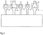
- Fig. 3 a further embodiment of the method according to the invention can be seen.
- numerous natural teeth 50 are molded and corresponding negative forms 54 are provided. This is done for the seven or eight teeth of each quadrant of a natural set of teeth, and also in different sizes, so that nature-identical negative shapes 54 are available in a tooth shape library.
- the corresponding nature-identical negative shape of the attachment 24 is then selected and used to provide the mold cavity 34 on the tooth to be treated.
- this method can be viewed as the realization of a tooth form key with shaping surfaces.
Landscapes
- Health & Medical Sciences (AREA)
- Oral & Maxillofacial Surgery (AREA)
- Dentistry (AREA)
- Epidemiology (AREA)
- Life Sciences & Earth Sciences (AREA)
- Animal Behavior & Ethology (AREA)
- General Health & Medical Sciences (AREA)
- Public Health (AREA)
- Veterinary Medicine (AREA)
- Dental Tools And Instruments Or Auxiliary Dental Instruments (AREA)
Claims (13)
- Procédé de fabrication d'une fixation (24) ou d'une saillie d'un appareil de polymérisation par rayonnement, qui est tourné vers un matériau de restauration dentaire (20) ou peut être dirigé vers celui-ci, pour un dispositif de production de restaurations dentaires comprenant un matériau de restauration dentaire polymérisable (20), un appareil de polymérisation par rayonnement, avec lequel le matériau de restauration dentaire polymérisable (20) peut être polymérisé au moyen de rayonnement lumineux, de rayonnement UV et/ou de rayonnement thermique pour produire une pièce de restauration dentaire (22), caractérisé en ce que la fixation ou la saillie (24), qui présente une surface de formage, qui correspond à la forme cible de la surface (52) du matériau de restauration dentaire (20) et forme un moule négatif (54) pour ce dernier dans la zone tournée vers le dispositif de polymérisation par rayonnement, est fixé dans sa forme sur son côté distal par un dispositif de CAO, notamment sur la base des données, qui correspondent à la forme extérieure de la pièce de restauration dentaire (22) et que la fixation (24) ou la saillie est fabriqué dans un matériau approprié, en particulier en silicone, au moyen d'un procédé de façonnage, en particulier l'impression 3D, le fraisage ou le moulage, pour représenter un moule négatif pour le contour souhaitée de la dent.
- Procédé selon la revendication 1, caractérisée en ce que la fixation (24) ou la saillie est constituée d'un matériau transparent et par ailleurs est fixé au dispositif de polymérisation par rayonnement
- Procédé selon la revendication 1, caractérisée en ce que la fixation (24) ou la saillie est constituée d'un matériau qui peut être et également formé d'avance, c'est-à-dire avant le polymérisation,
- Procédé selon l'une des revendications précédentes, caractérisée en ce que la fixation (24) ou la saillie est conçue de telle manière qu'elle présente essentiellement une forme conique ou tronconique sur les flancs latéraux (42).
- Procédé selon l'une des revendications précédentes, caractérisée en ce que la fixation (24) ou la saillie est conçue de telle sorte qu'elle est par ailleurs fixée par friction et/ou par engagement positif au dispositif de polymérisation par rayonnement et qu'une pression peut être exercée par ce biais sur le matériau de restauration dentaire encore mou (20).
- Procédé selon l'une des revendications précédentes, caractérisé en ce que la fixation (24) ou la saillie est produite par pression tridimensionnelle et sa surface (52) tournée vers le matériau de restauration dentaire (20) forme un moule négatif (54) pour le matériau de restauration dentaire (20), qui est conçue pour produire une empreinte à la manière d'un tampon dans le matériau de restauration dentaire (20).
- Procédé selon l'une des revendications précédentes, caractérisée en ce que l'attache (24) ou la saillie est fixée de manière amovible à unguide de lumière de l'appareil de polymérisation par rayonnement et est conçue en particulier comme produit à usage unique.
- Procédé selon l'une des revendications précédentes, caractérisé en ce que l'attache (24) ou la saillie est conçue de telle manière qu'il présente une forme de base fixe qui est reliée au guide de lumière de l'appareil de polymérisation par rayonnement, est modelée sur une forme de base typique des dents humaines, par exemple leur surface occlusale (44), et sur laquelle les structures requises peuvent être modelées en matériau transparent.
- Procédé selon l'une des revendications précédentes, caractérisé en ce qu'il est prévu une masse d'empreinte, par laquelle est prise une empreinte de l'antagoniste (50) de la dent (30) avec le matériau de restauration dentaire (20), et en ce que la masse d'empreinte, après avoir polymérisé, est utilisée pour fixer la forme de l'attachement (24) ou de la saillie.
- Procédé selon l'une des revendications précédentes, caractérisé en ce qu'une pluralité d'attaches ou de saillies correspondant aux dents humaines naturelles sont produites sous forme de moules négatifs (54), qui peuvent être pressés à la manière d'un tampon sur le matériau de restauration dentaire (20) en fonction de la position souhaitée de la dent et peuvent être utilisés pour former le matériau de restauration dentaire (20).
- Procédé selon l'une des revendications précédentes, caractérisé en ce que la fixation (24) ou la saillie est conçue de telle sorte qu'elle présente un logement pour l'extrémité avant (16) d'un guide de lumière, lequel logement pouvant être fixé par friction à l'extrémité avant (16) du guide de lumière par l'intermédiaire d'une bride.
- Fixation (24) ou saillie pour un dispositif de polymérisation par rayonnement, caractérisé en ce qu'elle est fabriquée selon le procédé selon la revendication 1, de sorte qu'il présente une surface de formage pour un matériau de restauration dentaire.
- Dispositif de production de restauration dentaire, comprenant un matériau de restauration dentaire polymérisable (20), un dispositif de polymérisation par rayonnement avec lequel le matériau de restauration dentaire polymérisable (20) peut être polymérisé au moyen de rayonnement lumineux, de rayonnement UV et/ou de rayonnement thermique pour produire une pièce de restauration dentaire (22), et une fixation (24) ou une saillie du dispositif de polymérisation par rayonnement, qui est tournée vers le matériau de restauration dentaire (20) ou qui peut être dirigée vers celui-ci, caractérisée en ce que la saillie ou la fixation (24) est fabriquée selon le procédé selon la revendication 1, de manière à présenter une surface de formage qui correspond à la forme cible de la surface (52) du matériau de restauration dentaire (20) et forme un moule négatif (54) pour celui-ci dans la zone tournée vers l'appareil de polymérisation par rayonnement.
Priority Applications (3)
| Application Number | Priority Date | Filing Date | Title |
|---|---|---|---|
| EP16173538.6A EP3254641B1 (fr) | 2016-06-08 | 2016-06-08 | Procédé de production d'un appareil de durcissement par rayonnement, d'une fixation et d'un appareil de production de restauration dentaire |
| US16/306,695 US11051922B2 (en) | 2016-06-08 | 2017-05-24 | Dental restoration production device and add-on or attachment |
| PCT/EP2017/062559 WO2017211588A1 (fr) | 2016-06-08 | 2017-05-24 | Dispositif de production d'une restauration dentaire et élément rapporté ou insert |
Applications Claiming Priority (1)
| Application Number | Priority Date | Filing Date | Title |
|---|---|---|---|
| EP16173538.6A EP3254641B1 (fr) | 2016-06-08 | 2016-06-08 | Procédé de production d'un appareil de durcissement par rayonnement, d'une fixation et d'un appareil de production de restauration dentaire |
Publications (2)
| Publication Number | Publication Date |
|---|---|
| EP3254641A1 EP3254641A1 (fr) | 2017-12-13 |
| EP3254641B1 true EP3254641B1 (fr) | 2020-12-09 |
Family
ID=56116324
Family Applications (1)
| Application Number | Title | Priority Date | Filing Date |
|---|---|---|---|
| EP16173538.6A Active EP3254641B1 (fr) | 2016-06-08 | 2016-06-08 | Procédé de production d'un appareil de durcissement par rayonnement, d'une fixation et d'un appareil de production de restauration dentaire |
Country Status (3)
| Country | Link |
|---|---|
| US (1) | US11051922B2 (fr) |
| EP (1) | EP3254641B1 (fr) |
| WO (1) | WO2017211588A1 (fr) |
Families Citing this family (5)
| Publication number | Priority date | Publication date | Assignee | Title |
|---|---|---|---|---|
| WO2020084533A1 (fr) * | 2018-10-25 | 2020-04-30 | 3M Innovative Properties Company | Précurseur de restauration dentaire imprimé en 3d avec élément de support et procédé de production |
| US11304788B2 (en) * | 2019-11-07 | 2022-04-19 | Orthosnap Corp. | Light concentrating adapter for dental curing |
| WO2021219228A1 (fr) * | 2020-04-30 | 2021-11-04 | Rayo 3D-Toothfill Oy | Préparation d'un objet de restauration |
| EP4342421A3 (fr) * | 2020-12-16 | 2024-06-19 | Ivoclar Vivadent AG | Capteur dentaire pour la zone intraorale |
| FR3120784A1 (fr) * | 2021-03-17 | 2022-09-23 | Dong Vu | Dispositif médical sur mesure pour restaurer l’anatomie occlusale d’une dent |
Family Cites Families (9)
| Publication number | Priority date | Publication date | Assignee | Title |
|---|---|---|---|---|
| SE435447B (sv) * | 1983-02-21 | 1984-10-01 | Dan Ericson | Sett och anordning for framstellning av en tandfyllning av ljusherdande material |
| US5030093A (en) * | 1988-06-10 | 1991-07-09 | Aaron Teitelbaum | Method and apparatus for dental restorative material |
| DE4233870A1 (de) | 1992-10-08 | 1994-04-14 | Heraeus Kulzer Gmbh | Schutzvorrichtung für ein medizinisches Bestrahlungsgerät |
| DE10234994A1 (de) * | 2002-07-31 | 2004-02-12 | Gerhard Bruckner | Zahnverblendung und Vorrichtung zur Aufbringung einer Zahnverblendung |
| US20040214130A1 (en) | 2003-04-25 | 2004-10-28 | Ultradent Products, Inc. | Flexible translucent protective covers used to protect dental appliances from rigid light emitting devices |
| US7217131B2 (en) * | 2004-11-26 | 2007-05-15 | Vuillemot William C | Method for dental restoration and kit |
| EP2364123B1 (fr) * | 2008-10-24 | 2016-12-28 | DENTSPLY International Inc. | Récipient pour stocker et distribuer une matière liquide |
| US8753114B2 (en) * | 2010-02-26 | 2014-06-17 | William C. Vuillemot | Method for dental restoration and related kit |
| WO2016066552A1 (fr) * | 2014-10-27 | 2016-05-06 | 3Shape A/S | Procédé, système et interface utilisateur pour créer une conception numérique en vue d'une utilisation dans la fabrication d'une coque de moulage pour restauration dentaire |
-
2016
- 2016-06-08 EP EP16173538.6A patent/EP3254641B1/fr active Active
-
2017
- 2017-05-24 US US16/306,695 patent/US11051922B2/en active Active
- 2017-05-24 WO PCT/EP2017/062559 patent/WO2017211588A1/fr not_active Ceased
Non-Patent Citations (1)
| Title |
|---|
| None * |
Also Published As
| Publication number | Publication date |
|---|---|
| US11051922B2 (en) | 2021-07-06 |
| EP3254641A1 (fr) | 2017-12-13 |
| US20190117358A1 (en) | 2019-04-25 |
| WO2017211588A1 (fr) | 2017-12-14 |
Similar Documents
| Publication | Publication Date | Title |
|---|---|---|
| EP3254641B1 (fr) | Procédé de production d'un appareil de durcissement par rayonnement, d'une fixation et d'un appareil de production de restauration dentaire | |
| DE60022506T2 (de) | Endodontisches stiftsystem | |
| EP3242628B1 (fr) | Procédé pour la fabrication d'une prothèse dentaire | |
| EP2862539B1 (fr) | Dispositif de positionnement dentaire | |
| EP2952154B1 (fr) | Procédé de fabrication de restaurations dentaires et dispositif de fabrication de céramiques dentaires | |
| EP2144574B1 (fr) | Appareil manuel destiné à émettre une matière de remplissage pâteuse | |
| EP3649983A1 (fr) | Procédé de fabrication de prothèses dentaires | |
| DE112007001376T5 (de) | Orthodontisches Indirektklebtray mit Feuchtigkeitskontrolle | |
| DE69502965T2 (de) | Kronen-wurzel wiederherstellungseinheit aus verbundmaterial mit elastizitätsmodulgradient und dessen herstellung | |
| DE102008062869A1 (de) | Interdentalvorrichtung | |
| EP3572035B1 (fr) | Prothèse dentaire, produit semi-fini associé ainsi que jeu de pièces | |
| DE102012211332A1 (de) | Zahnersatz, Verblendung für einen Zahnersatz und Herstellungsverfahren | |
| EP2952155B1 (fr) | Dispositif de fabrication de céramique dentaire | |
| DE10234994A1 (de) | Zahnverblendung und Vorrichtung zur Aufbringung einer Zahnverblendung | |
| WO2020057872A1 (fr) | Demi-produit pour la fabrication de dents prothétiques et procédé pour sa fabrication et son traitement | |
| DE102015106424A1 (de) | Verfahren zur Herstellung von Zahnersatz mit einem Kunststoffkern | |
| EP1901676B1 (fr) | Procédé et ensemble de substances pour la fabrication de prothèses dentaires | |
| EP3056165B1 (fr) | Dispositif medical dentaire comprenant une coque de transfert | |
| EP3157460B1 (fr) | Base de prothèse et procédé pour relier par liaison de matière au moins une dent artificielle à une base de prothèse | |
| WO2018069117A1 (fr) | Ébauche de plaque-base de prothèse préformée prise dans de la cire | |
| DE19513568C1 (de) | Präparationsschleifer-Inlay-System | |
| DE102021112178B4 (de) | Verfahren und Vorrichtung zur Herstellung einer Dentalprothese | |
| WO2018192625A1 (fr) | Module de support de matériau dentaire réutilisable et système de support de matériau dentaire réutilisable constitué d'ensembles de modules de support de matériau, et procédé | |
| DE102008011447A1 (de) | Formvorrichtung und Verfahren zum Herstellen einer Heilkappe, sowie Set und Heilkappe | |
| DE19512625C2 (de) | Präparationsschleifer-Inlay-System |
Legal Events
| Date | Code | Title | Description |
|---|---|---|---|
| PUAI | Public reference made under article 153(3) epc to a published international application that has entered the european phase |
Free format text: ORIGINAL CODE: 0009012 |
|
| STAA | Information on the status of an ep patent application or granted ep patent |
Free format text: STATUS: THE APPLICATION HAS BEEN PUBLISHED |
|
| AK | Designated contracting states |
Kind code of ref document: A1 Designated state(s): AL AT BE BG CH CY CZ DE DK EE ES FI FR GB GR HR HU IE IS IT LI LT LU LV MC MK MT NL NO PL PT RO RS SE SI SK SM TR |
|
| AX | Request for extension of the european patent |
Extension state: BA ME |
|
| STAA | Information on the status of an ep patent application or granted ep patent |
Free format text: STATUS: REQUEST FOR EXAMINATION WAS MADE |
|
| 17P | Request for examination filed |
Effective date: 20180508 |
|
| RBV | Designated contracting states (corrected) |
Designated state(s): AL AT BE BG CH CY CZ DE DK EE ES FI FR GB GR HR HU IE IS IT LI LT LU LV MC MK MT NL NO PL PT RO RS SE SI SK SM TR |
|
| STAA | Information on the status of an ep patent application or granted ep patent |
Free format text: STATUS: EXAMINATION IS IN PROGRESS |
|
| 17Q | First examination report despatched |
Effective date: 20190917 |
|
| GRAP | Despatch of communication of intention to grant a patent |
Free format text: ORIGINAL CODE: EPIDOSNIGR1 |
|
| STAA | Information on the status of an ep patent application or granted ep patent |
Free format text: STATUS: GRANT OF PATENT IS INTENDED |
|
| INTG | Intention to grant announced |
Effective date: 20200629 |
|
| GRAS | Grant fee paid |
Free format text: ORIGINAL CODE: EPIDOSNIGR3 |
|
| GRAA | (expected) grant |
Free format text: ORIGINAL CODE: 0009210 |
|
| STAA | Information on the status of an ep patent application or granted ep patent |
Free format text: STATUS: THE PATENT HAS BEEN GRANTED |
|
| AK | Designated contracting states |
Kind code of ref document: B1 Designated state(s): AL AT BE BG CH CY CZ DE DK EE ES FI FR GB GR HR HU IE IS IT LI LT LU LV MC MK MT NL NO PL PT RO RS SE SI SK SM TR |
|
| REG | Reference to a national code |
Ref country code: GB Ref legal event code: FG4D Free format text: NOT ENGLISH |
|
| REG | Reference to a national code |
Ref country code: AT Ref legal event code: REF Ref document number: 1342586 Country of ref document: AT Kind code of ref document: T Effective date: 20201215 Ref country code: CH Ref legal event code: EP |
|
| REG | Reference to a national code |
Ref country code: DE Ref legal event code: R096 Ref document number: 502016011896 Country of ref document: DE |
|
| REG | Reference to a national code |
Ref country code: IE Ref legal event code: FG4D Free format text: LANGUAGE OF EP DOCUMENT: GERMAN |
|
| REG | Reference to a national code |
Ref country code: CH Ref legal event code: NV Representative=s name: KELLER SCHNEIDER PATENT- UND MARKENANWAELTE AG, CH |
|
| PG25 | Lapsed in a contracting state [announced via postgrant information from national office to epo] |
Ref country code: RS Free format text: LAPSE BECAUSE OF FAILURE TO SUBMIT A TRANSLATION OF THE DESCRIPTION OR TO PAY THE FEE WITHIN THE PRESCRIBED TIME-LIMIT Effective date: 20201209 Ref country code: NO Free format text: LAPSE BECAUSE OF FAILURE TO SUBMIT A TRANSLATION OF THE DESCRIPTION OR TO PAY THE FEE WITHIN THE PRESCRIBED TIME-LIMIT Effective date: 20210309 Ref country code: FI Free format text: LAPSE BECAUSE OF FAILURE TO SUBMIT A TRANSLATION OF THE DESCRIPTION OR TO PAY THE FEE WITHIN THE PRESCRIBED TIME-LIMIT Effective date: 20201209 Ref country code: GR Free format text: LAPSE BECAUSE OF FAILURE TO SUBMIT A TRANSLATION OF THE DESCRIPTION OR TO PAY THE FEE WITHIN THE PRESCRIBED TIME-LIMIT Effective date: 20210310 |
|
| PG25 | Lapsed in a contracting state [announced via postgrant information from national office to epo] |
Ref country code: BG Free format text: LAPSE BECAUSE OF FAILURE TO SUBMIT A TRANSLATION OF THE DESCRIPTION OR TO PAY THE FEE WITHIN THE PRESCRIBED TIME-LIMIT Effective date: 20210309 Ref country code: SE Free format text: LAPSE BECAUSE OF FAILURE TO SUBMIT A TRANSLATION OF THE DESCRIPTION OR TO PAY THE FEE WITHIN THE PRESCRIBED TIME-LIMIT Effective date: 20201209 Ref country code: LV Free format text: LAPSE BECAUSE OF FAILURE TO SUBMIT A TRANSLATION OF THE DESCRIPTION OR TO PAY THE FEE WITHIN THE PRESCRIBED TIME-LIMIT Effective date: 20201209 |
|
| REG | Reference to a national code |
Ref country code: NL Ref legal event code: MP Effective date: 20201209 |
|
| PG25 | Lapsed in a contracting state [announced via postgrant information from national office to epo] |
Ref country code: HR Free format text: LAPSE BECAUSE OF FAILURE TO SUBMIT A TRANSLATION OF THE DESCRIPTION OR TO PAY THE FEE WITHIN THE PRESCRIBED TIME-LIMIT Effective date: 20201209 Ref country code: NL Free format text: LAPSE BECAUSE OF FAILURE TO SUBMIT A TRANSLATION OF THE DESCRIPTION OR TO PAY THE FEE WITHIN THE PRESCRIBED TIME-LIMIT Effective date: 20201209 |
|
| REG | Reference to a national code |
Ref country code: LT Ref legal event code: MG9D |
|
| PG25 | Lapsed in a contracting state [announced via postgrant information from national office to epo] |
Ref country code: SM Free format text: LAPSE BECAUSE OF FAILURE TO SUBMIT A TRANSLATION OF THE DESCRIPTION OR TO PAY THE FEE WITHIN THE PRESCRIBED TIME-LIMIT Effective date: 20201209 Ref country code: LT Free format text: LAPSE BECAUSE OF FAILURE TO SUBMIT A TRANSLATION OF THE DESCRIPTION OR TO PAY THE FEE WITHIN THE PRESCRIBED TIME-LIMIT Effective date: 20201209 Ref country code: CZ Free format text: LAPSE BECAUSE OF FAILURE TO SUBMIT A TRANSLATION OF THE DESCRIPTION OR TO PAY THE FEE WITHIN THE PRESCRIBED TIME-LIMIT Effective date: 20201209 Ref country code: EE Free format text: LAPSE BECAUSE OF FAILURE TO SUBMIT A TRANSLATION OF THE DESCRIPTION OR TO PAY THE FEE WITHIN THE PRESCRIBED TIME-LIMIT Effective date: 20201209 Ref country code: RO Free format text: LAPSE BECAUSE OF FAILURE TO SUBMIT A TRANSLATION OF THE DESCRIPTION OR TO PAY THE FEE WITHIN THE PRESCRIBED TIME-LIMIT Effective date: 20201209 Ref country code: PT Free format text: LAPSE BECAUSE OF FAILURE TO SUBMIT A TRANSLATION OF THE DESCRIPTION OR TO PAY THE FEE WITHIN THE PRESCRIBED TIME-LIMIT Effective date: 20210409 Ref country code: SK Free format text: LAPSE BECAUSE OF FAILURE TO SUBMIT A TRANSLATION OF THE DESCRIPTION OR TO PAY THE FEE WITHIN THE PRESCRIBED TIME-LIMIT Effective date: 20201209 |
|
| PG25 | Lapsed in a contracting state [announced via postgrant information from national office to epo] |
Ref country code: PL Free format text: LAPSE BECAUSE OF FAILURE TO SUBMIT A TRANSLATION OF THE DESCRIPTION OR TO PAY THE FEE WITHIN THE PRESCRIBED TIME-LIMIT Effective date: 20201209 |
|
| REG | Reference to a national code |
Ref country code: DE Ref legal event code: R097 Ref document number: 502016011896 Country of ref document: DE |
|
| PG25 | Lapsed in a contracting state [announced via postgrant information from national office to epo] |
Ref country code: IS Free format text: LAPSE BECAUSE OF FAILURE TO SUBMIT A TRANSLATION OF THE DESCRIPTION OR TO PAY THE FEE WITHIN THE PRESCRIBED TIME-LIMIT Effective date: 20210409 |
|
| PLBE | No opposition filed within time limit |
Free format text: ORIGINAL CODE: 0009261 |
|
| STAA | Information on the status of an ep patent application or granted ep patent |
Free format text: STATUS: NO OPPOSITION FILED WITHIN TIME LIMIT |
|
| PG25 | Lapsed in a contracting state [announced via postgrant information from national office to epo] |
Ref country code: AL Free format text: LAPSE BECAUSE OF FAILURE TO SUBMIT A TRANSLATION OF THE DESCRIPTION OR TO PAY THE FEE WITHIN THE PRESCRIBED TIME-LIMIT Effective date: 20201209 |
|
| 26N | No opposition filed |
Effective date: 20210910 |
|
| PG25 | Lapsed in a contracting state [announced via postgrant information from national office to epo] |
Ref country code: DK Free format text: LAPSE BECAUSE OF FAILURE TO SUBMIT A TRANSLATION OF THE DESCRIPTION OR TO PAY THE FEE WITHIN THE PRESCRIBED TIME-LIMIT Effective date: 20201209 Ref country code: SI Free format text: LAPSE BECAUSE OF FAILURE TO SUBMIT A TRANSLATION OF THE DESCRIPTION OR TO PAY THE FEE WITHIN THE PRESCRIBED TIME-LIMIT Effective date: 20201209 |
|
| PG25 | Lapsed in a contracting state [announced via postgrant information from national office to epo] |
Ref country code: ES Free format text: LAPSE BECAUSE OF FAILURE TO SUBMIT A TRANSLATION OF THE DESCRIPTION OR TO PAY THE FEE WITHIN THE PRESCRIBED TIME-LIMIT Effective date: 20201209 Ref country code: MC Free format text: LAPSE BECAUSE OF FAILURE TO SUBMIT A TRANSLATION OF THE DESCRIPTION OR TO PAY THE FEE WITHIN THE PRESCRIBED TIME-LIMIT Effective date: 20201209 |
|
| GBPC | Gb: european patent ceased through non-payment of renewal fee |
Effective date: 20210608 |
|
| REG | Reference to a national code |
Ref country code: BE Ref legal event code: MM Effective date: 20210630 |
|
| PG25 | Lapsed in a contracting state [announced via postgrant information from national office to epo] |
Ref country code: LU Free format text: LAPSE BECAUSE OF NON-PAYMENT OF DUE FEES Effective date: 20210608 |
|
| PG25 | Lapsed in a contracting state [announced via postgrant information from national office to epo] |
Ref country code: IE Free format text: LAPSE BECAUSE OF NON-PAYMENT OF DUE FEES Effective date: 20210608 Ref country code: GB Free format text: LAPSE BECAUSE OF NON-PAYMENT OF DUE FEES Effective date: 20210608 |
|
| PG25 | Lapsed in a contracting state [announced via postgrant information from national office to epo] |
Ref country code: IS Free format text: LAPSE BECAUSE OF FAILURE TO SUBMIT A TRANSLATION OF THE DESCRIPTION OR TO PAY THE FEE WITHIN THE PRESCRIBED TIME-LIMIT Effective date: 20210409 Ref country code: FR Free format text: LAPSE BECAUSE OF NON-PAYMENT OF DUE FEES Effective date: 20210630 |
|
| PG25 | Lapsed in a contracting state [announced via postgrant information from national office to epo] |
Ref country code: BE Free format text: LAPSE BECAUSE OF NON-PAYMENT OF DUE FEES Effective date: 20210630 |
|
| PG25 | Lapsed in a contracting state [announced via postgrant information from national office to epo] |
Ref country code: HU Free format text: LAPSE BECAUSE OF FAILURE TO SUBMIT A TRANSLATION OF THE DESCRIPTION OR TO PAY THE FEE WITHIN THE PRESCRIBED TIME-LIMIT; INVALID AB INITIO Effective date: 20160608 |
|
| PG25 | Lapsed in a contracting state [announced via postgrant information from national office to epo] |
Ref country code: CY Free format text: LAPSE BECAUSE OF FAILURE TO SUBMIT A TRANSLATION OF THE DESCRIPTION OR TO PAY THE FEE WITHIN THE PRESCRIBED TIME-LIMIT Effective date: 20201209 |
|
| P01 | Opt-out of the competence of the unified patent court (upc) registered |
Effective date: 20230607 |
|
| PGFP | Annual fee paid to national office [announced via postgrant information from national office to epo] |
Ref country code: AT Payment date: 20230509 Year of fee payment: 8 |
|
| PG25 | Lapsed in a contracting state [announced via postgrant information from national office to epo] |
Ref country code: MK Free format text: LAPSE BECAUSE OF FAILURE TO SUBMIT A TRANSLATION OF THE DESCRIPTION OR TO PAY THE FEE WITHIN THE PRESCRIBED TIME-LIMIT Effective date: 20201209 |
|
| PG25 | Lapsed in a contracting state [announced via postgrant information from national office to epo] |
Ref country code: TR Free format text: LAPSE BECAUSE OF FAILURE TO SUBMIT A TRANSLATION OF THE DESCRIPTION OR TO PAY THE FEE WITHIN THE PRESCRIBED TIME-LIMIT Effective date: 20201209 |
|
| PG25 | Lapsed in a contracting state [announced via postgrant information from national office to epo] |
Ref country code: MT Free format text: LAPSE BECAUSE OF FAILURE TO SUBMIT A TRANSLATION OF THE DESCRIPTION OR TO PAY THE FEE WITHIN THE PRESCRIBED TIME-LIMIT Effective date: 20201209 |
|
| REG | Reference to a national code |
Ref country code: AT Ref legal event code: MM01 Ref document number: 1342586 Country of ref document: AT Kind code of ref document: T Effective date: 20240608 |
|
| PG25 | Lapsed in a contracting state [announced via postgrant information from national office to epo] |
Ref country code: AT Free format text: LAPSE BECAUSE OF NON-PAYMENT OF DUE FEES Effective date: 20240608 |
|
| PGFP | Annual fee paid to national office [announced via postgrant information from national office to epo] |
Ref country code: DE Payment date: 20250623 Year of fee payment: 10 |
|
| PGFP | Annual fee paid to national office [announced via postgrant information from national office to epo] |
Ref country code: IT Payment date: 20250605 Year of fee payment: 10 |
|
| PGFP | Annual fee paid to national office [announced via postgrant information from national office to epo] |
Ref country code: CH Payment date: 20250717 Year of fee payment: 10 |