EP3255233A1 - Entraînement comprenant un dispositif de mise en mouvement pour un vantail coulissant en tant que vantail coulissant et basculant relevable ou vantail coulissant relevable - Google Patents
Entraînement comprenant un dispositif de mise en mouvement pour un vantail coulissant en tant que vantail coulissant et basculant relevable ou vantail coulissant relevable Download PDFInfo
- Publication number
- EP3255233A1 EP3255233A1 EP17001304.9A EP17001304A EP3255233A1 EP 3255233 A1 EP3255233 A1 EP 3255233A1 EP 17001304 A EP17001304 A EP 17001304A EP 3255233 A1 EP3255233 A1 EP 3255233A1
- Authority
- EP
- European Patent Office
- Prior art keywords
- drive
- wing
- adjusting device
- spindle
- sliding
- Prior art date
- Legal status (The legal status is an assumption and is not a legal conclusion. Google has not performed a legal analysis and makes no representation as to the accuracy of the status listed.)
- Granted
Links
Images


Classifications
-
- E—FIXED CONSTRUCTIONS
- E05—LOCKS; KEYS; WINDOW OR DOOR FITTINGS; SAFES
- E05F—DEVICES FOR MOVING WINGS INTO OPEN OR CLOSED POSITION; CHECKS FOR WINGS; WING FITTINGS NOT OTHERWISE PROVIDED FOR, CONCERNED WITH THE FUNCTIONING OF THE WING
- E05F15/00—Power-operated mechanisms for wings
- E05F15/60—Power-operated mechanisms for wings using electrical actuators
- E05F15/603—Power-operated mechanisms for wings using electrical actuators using rotary electromotors
- E05F15/632—Power-operated mechanisms for wings using electrical actuators using rotary electromotors for horizontally-sliding wings
- E05F15/652—Power-operated mechanisms for wings using electrical actuators using rotary electromotors for horizontally-sliding wings operated by screw-and-nut mechanisms
-
- E—FIXED CONSTRUCTIONS
- E05—LOCKS; KEYS; WINDOW OR DOOR FITTINGS; SAFES
- E05D—HINGES OR SUSPENSION DEVICES FOR DOORS, WINDOWS OR WINGS
- E05D15/00—Suspension arrangements for wings
- E05D15/56—Suspension arrangements for wings with successive different movements
- E05D15/565—Suspension arrangements for wings with successive different movements for raising wings before sliding
-
- E—FIXED CONSTRUCTIONS
- E05—LOCKS; KEYS; WINDOW OR DOOR FITTINGS; SAFES
- E05F—DEVICES FOR MOVING WINGS INTO OPEN OR CLOSED POSITION; CHECKS FOR WINGS; WING FITTINGS NOT OTHERWISE PROVIDED FOR, CONCERNED WITH THE FUNCTIONING OF THE WING
- E05F15/00—Power-operated mechanisms for wings
- E05F15/60—Power-operated mechanisms for wings using electrical actuators
- E05F15/603—Power-operated mechanisms for wings using electrical actuators using rotary electromotors
- E05F15/632—Power-operated mechanisms for wings using electrical actuators using rotary electromotors for horizontally-sliding wings
-
- E—FIXED CONSTRUCTIONS
- E05—LOCKS; KEYS; WINDOW OR DOOR FITTINGS; SAFES
- E05Y—INDEXING SCHEME ASSOCIATED WITH SUBCLASSES E05D AND E05F, RELATING TO CONSTRUCTION ELEMENTS, ELECTRIC CONTROL, POWER SUPPLY, POWER SIGNAL OR TRANSMISSION, USER INTERFACES, MOUNTING OR COUPLING, DETAILS, ACCESSORIES, AUXILIARY OPERATIONS NOT OTHERWISE PROVIDED FOR, APPLICATION THEREOF
- E05Y2201/00—Constructional elements; Accessories therefor
- E05Y2201/40—Motors; Magnets; Springs; Weights; Accessories therefor
- E05Y2201/404—Function thereof
- E05Y2201/406—Function thereof for a secondary movement of the wing
-
- E—FIXED CONSTRUCTIONS
- E05—LOCKS; KEYS; WINDOW OR DOOR FITTINGS; SAFES
- E05Y—INDEXING SCHEME ASSOCIATED WITH SUBCLASSES E05D AND E05F, RELATING TO CONSTRUCTION ELEMENTS, ELECTRIC CONTROL, POWER SUPPLY, POWER SIGNAL OR TRANSMISSION, USER INTERFACES, MOUNTING OR COUPLING, DETAILS, ACCESSORIES, AUXILIARY OPERATIONS NOT OTHERWISE PROVIDED FOR, APPLICATION THEREOF
- E05Y2201/00—Constructional elements; Accessories therefor
- E05Y2201/60—Suspension or transmission members; Accessories therefor
- E05Y2201/622—Suspension or transmission members elements
- E05Y2201/684—Rails; Tracks
-
- E—FIXED CONSTRUCTIONS
- E05—LOCKS; KEYS; WINDOW OR DOOR FITTINGS; SAFES
- E05Y—INDEXING SCHEME ASSOCIATED WITH SUBCLASSES E05D AND E05F, RELATING TO CONSTRUCTION ELEMENTS, ELECTRIC CONTROL, POWER SUPPLY, POWER SIGNAL OR TRANSMISSION, USER INTERFACES, MOUNTING OR COUPLING, DETAILS, ACCESSORIES, AUXILIARY OPERATIONS NOT OTHERWISE PROVIDED FOR, APPLICATION THEREOF
- E05Y2600/00—Mounting or coupling arrangements for elements provided for in this subclass
- E05Y2600/40—Mounting location; Visibility of the elements
- E05Y2600/456—Mounting location; Visibility of the elements in or on a suspension member
-
- E—FIXED CONSTRUCTIONS
- E05—LOCKS; KEYS; WINDOW OR DOOR FITTINGS; SAFES
- E05Y—INDEXING SCHEME ASSOCIATED WITH SUBCLASSES E05D AND E05F, RELATING TO CONSTRUCTION ELEMENTS, ELECTRIC CONTROL, POWER SUPPLY, POWER SIGNAL OR TRANSMISSION, USER INTERFACES, MOUNTING OR COUPLING, DETAILS, ACCESSORIES, AUXILIARY OPERATIONS NOT OTHERWISE PROVIDED FOR, APPLICATION THEREOF
- E05Y2600/00—Mounting or coupling arrangements for elements provided for in this subclass
- E05Y2600/50—Mounting methods; Positioning
- E05Y2600/52—Toolless
- E05Y2600/53—Snapping
-
- E—FIXED CONSTRUCTIONS
- E05—LOCKS; KEYS; WINDOW OR DOOR FITTINGS; SAFES
- E05Y—INDEXING SCHEME ASSOCIATED WITH SUBCLASSES E05D AND E05F, RELATING TO CONSTRUCTION ELEMENTS, ELECTRIC CONTROL, POWER SUPPLY, POWER SIGNAL OR TRANSMISSION, USER INTERFACES, MOUNTING OR COUPLING, DETAILS, ACCESSORIES, AUXILIARY OPERATIONS NOT OTHERWISE PROVIDED FOR, APPLICATION THEREOF
- E05Y2800/00—Details, accessories and auxiliary operations not otherwise provided for
-
- E—FIXED CONSTRUCTIONS
- E05—LOCKS; KEYS; WINDOW OR DOOR FITTINGS; SAFES
- E05Y—INDEXING SCHEME ASSOCIATED WITH SUBCLASSES E05D AND E05F, RELATING TO CONSTRUCTION ELEMENTS, ELECTRIC CONTROL, POWER SUPPLY, POWER SIGNAL OR TRANSMISSION, USER INTERFACES, MOUNTING OR COUPLING, DETAILS, ACCESSORIES, AUXILIARY OPERATIONS NOT OTHERWISE PROVIDED FOR, APPLICATION THEREOF
- E05Y2900/00—Application of doors, windows, wings or fittings thereof
- E05Y2900/10—Application of doors, windows, wings or fittings thereof for buildings or parts thereof
- E05Y2900/13—Type of wing
- E05Y2900/132—Doors
-
- E—FIXED CONSTRUCTIONS
- E05—LOCKS; KEYS; WINDOW OR DOOR FITTINGS; SAFES
- E05Y—INDEXING SCHEME ASSOCIATED WITH SUBCLASSES E05D AND E05F, RELATING TO CONSTRUCTION ELEMENTS, ELECTRIC CONTROL, POWER SUPPLY, POWER SIGNAL OR TRANSMISSION, USER INTERFACES, MOUNTING OR COUPLING, DETAILS, ACCESSORIES, AUXILIARY OPERATIONS NOT OTHERWISE PROVIDED FOR, APPLICATION THEREOF
- E05Y2900/00—Application of doors, windows, wings or fittings thereof
- E05Y2900/10—Application of doors, windows, wings or fittings thereof for buildings or parts thereof
- E05Y2900/13—Type of wing
- E05Y2900/148—Windows
Definitions
- the invention relates to a drive with an adjusting device for a sliding wing as lifting slide sliding or lifting sliding sash for a window or a door according to the preamble of claim 1.
- the sliding wings of systems as lift-slide sash or lift-slide sash for a window or door often have a relatively high mass.
- closing requires application of resistance to the weight of the wing to avoid abrupt dropping of the wing.
- the known drives with an adjustment are mounted without further cover, so severely affects the appearance and do not provide enough protection against possible incoming dirt, for example, by incident chips, which may damage the drive with the adjustment result.
- the risk of injury during assembly is increased by disturbing overhead visible components.
- visible components offer more possibilities for manipulation from the outside. An assembly of such a drive with the adjustment, turns out to be complicated from the known prior art.
- a control device for a lift-and-slide wing having at least two carriages each having rollers to be slid on a track in a direction parallel to the extension of the lift-and-slide wing or along the track.
- an electrically driven lifting drive and two vertical control rods is arranged, of which the one control rod at the lower end of the vertical rail via a deflection and coupling device with the carriage coupled, for adjusting the height position of the rollers, and wherein the second control rod of the at least two control rods is coupled to the lifting drive.
- the two vertical control rods are thrust coupled across transverse arms in a transmission housing so that movement of the second control rod driven by the linear actuator is transferable to the first vertical control rod.
- the present control device is large in construction and requires a corresponding amount of space in the wing. Furthermore, the components of the control device are distributed widely spaced from each other along the length of the guide rail, which complicates assembly due to individual component components. The functional components of the control device are also unprotected against dirt and other influences in the wing.
- the object of the present invention is therefore to eliminate the known deficiencies and in contrast provides with little effort and at low cost a drive with an adjustment for a sliding wing as lifting sliding sash or lifting sliding sash for a window or a door ready, in addition In a simple, fast, safe and precise manner, it can also be retrofitted and adjusted, as well as demounted.
- the drive and the adjusting device are to be arranged so that they are suitable for a sliding wing as a lifting sliding sash or lifting sliding sash for a window or door.
- the wing at least two carriages, each with rollers to be moved on a running rail in a direction parallel to the extension of the wing or along a running rail.
- an actuating element with a switch is arranged on the vertical spar of the wing, which switches the drive with the adjusting device for opening or closing.
- the movable wing can be brought relative to the fixed frame and the fixed mounted wing or door panel from the closed position to the raised open position. In the raised position can then move the wing in a relation to the fixed frame and the fixedly mounted wing or fixed door panel, but on the other hand also bring into a secure shifted ventilation position or a portion of a through hole.
- the drive is preferably added to the adjusting device in the mounted state in a U-shaped profiled guide rail.
- the drive has a circuit board, a motor and a transmission which drive a clutch. With power transmission from the clutch to the adjusting a arranged in a guide rail fitting displaced displaced.
- the individual components of the adjusting device are completely enveloped in a housing, wherein the housing with the guide rail receives a dimensionally stable fixed connection.
- the motor in particular the electric motor, is connected to the transmission and the circuit board and forms a unit fixed to one another as a drive.
- the transmission is connected via the coupling with a spindle to drive a carriage.
- the spindle is preferably rotatably supported on two bearings and mounted axially non-displaceable.
- the carriage is rotationally fixed in the housing, but arranged movable along the guide rail.
- the carriage is rotatably connected by means of a threaded portion with the spindle and preferably has a bore in extension of the central axis. The bore allows for a more stable hold and reduces the bending moments of the spindle, with the spindle in the bore additionally held leader.
- the bore is arranged on both sides of the threaded portion.
- the support surface of the carriage in the housing and on a drive rod of the fitting is increased simultaneously in the longitudinal direction. This absorbs forces to be absorbed, for example the Reduces braking force and increases a counteracting lever, so that the wear is reduced.
- a drive shaft of the transmission is provided with a first coupling part of a dog clutch, which is in engagement with a second coupling part of the clutch.
- the claws of the coupling parts are not directly adjacent to each other, but are separated by a coupling ring of an elastic material. Through the interaction of the components of the coupling existing clearance or tolerances is compensated.
- the carriage consists of a driver and a nut.
- the mother is T-shaped in the longitudinal direction to the drive and has for this purpose the centrally arranged threaded portion, wherein a formation of the bore having semicircular cutout is arranged on the respective sides.
- the driver is U-shaped in the longitudinal direction to the drive and has a recess which is in positive connection to the threaded portion. Also, semi-circular cutouts are formed on the respective sides of the recess to form the bore. In the coupled position of the driver with the nut, the semi-circular cutouts form the bore.
- the carriage is fastened with its driver to the drive rod of the fitting by means of a riveted joint and held in a leading position in the housing.
- the drive rod is formed bent in the direction of adjustment. Possibly occurring frictional resistance by a rivet projection, on the mounted in the guide rail movement of the drive rod, are thus excluded.
- the drive with the adjusting device regardless of the installation of the other fitting to the wing is concealed mountable.
- the size and weight of the window or door also dictate the number of drives to the adjuster to increase the drive force when needed.
- the adjusting device has a manually actuated emergency unlocking device for manual movement of the spindle arranged in the adjusting device with transmission to the fitting of the lifting sliding sliding wing or lifting sliding wing.
- a manually operable tool For operation engages in an opening of the housing of the adjusting a manually operable tool directly to the arranged spindle, which can be rotatably adjusted.
- the Fig. 1 shows in perspective view a displaceable wing 3 and a fixed-mounted wing or door panel 50 which is adjacent thereto.
- An actuator 51 with a switch controls a arranged on the vertical spar 52 drive 1 with an adjustment 2, which is not shown on the horizontal bar 53 arranged carriage with change of roles to the carriage in the altitude controls.
- the movable wing 3 can relative to the fixed frame 54 and the fixed mounted wing or door panel 50 from the in the Fig. 1 having brought closed position in the raised open position. In the raised position can then move the wing 3 in a position not shown relative to the fixed frame 54 and the fixed mounted wing or fixed door panel 50, but on the other hand bring in a secure shifted ventilation position or a portion of a through hole.
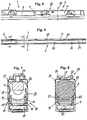
- the drive 1 is shown connected to the adjusting device 2 in the mounted state in a U-shaped profiled guide rail 9.
- the drive 1 has a circuit board 5, a motor 6 and a transmission 7, which drive a clutch 8.
- With power transmission from the clutch 8 to the adjusting device 2 is after Fig. 7 arranged in a guide rail 9 of the drive 1 fitting 10 displaced displaced.
- the adjusting device 2 is mounted in a housing 11 and is with the guide rail 9 a dimensionally stable fixed connection 12 a.
- the drive 1 is supported by a holder 13 perpendicular to the drive direction of the fitting 10, wherein at least one arranged on the holder 13 locking projection 14, 15 and arranged on the guide rail 9 franking 16, 17 by means of a latching snap device 18 form a releasably attachable connection ,
- the holder 13 is formed from a receiving plate 19 and a mounting plate 20 consisting of angular.
- the receiving plate 19 is after Fig. 7 aligned in the longitudinal direction of the guide rail 9 in cross-section with its outer side 21 of the inner cross-sectional contour 22 of the guide rail 9 adapted.
- the inside 23 of the receiving plate 19 is also the cylindrical cross-sectional shape of the motor 6 after Fig. 8 adapted, wherein in the assembled state, the motor 6 to the inside 23 of the receiving plate 19 has a minimum clearance to avoid stress.
- the aligned perpendicular to the opening of the guide rail 9 mounting plate 20 connects the motor 6 and thus the coupled components of the drive 1 by means of fastening screws frictionally to a one-piece unit.
- the locking projections 14, 15 provided with an inlet slope, which are arranged elastically on the outer side 21 of the receiving plate 19 of the holder 13.
- the guide rail 9 to the central axis 24 of the adjusting device 2 according to Fig. 2 formed symmetrically at least in the area for suspending the drive 1.
- the central axis 24 are each equally spaced from each other a cutout 25 for supporting the motor 6, the franking 16 of the locking snap connection and the fixed connection 12 of the adjusting device 2 are arranged.
- the housing 11 has a plurality of bearing points and consists of two housing halves 26, 27.
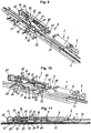
- the housing halves 26, 27 are after mounting with the stored in the housing 11 components preferably after Fig. 9 positively connected by fastening screws. Other connection options are also conceivable.
- the adjusting device 2 can be mounted in a known manner to the guide rail 9. These are on the legs of the guide rail 9 after FIGS. 9 to 11 Openings 62 are provided for mounting pins 63 or clamping pins, which are fixed positively and non-positively to the legs of the guide rail 9. In the housing 11 are congruently two through holes 64 through which the pins 63 are pushed through.
- the guide elements 30 are preferably made in one piece with the housing 11 and formed in cross-section to the housing 11 L-shaped with the open end to the inside of the housing 11 and together form a rear handle.
- the lines 29 can be easily inserted into the rear grip of the guide elements 30.
- the adjusting device 2 is shown in the open housing 11 and in Fig. 10 a part of the adjusting device 2 is shown without a housing half 27 for a simplified overview.
- the motor 6, in particular the electric motor, is connected to the transmission 7 and the circuit board 5 and together form a unit fixed to one another as the drive 1.
- the transmission 7 is connected via the coupling 8 to a spindle 31, which is rotatably mounted via the drive 1 to a sled 32 after Fig. 9 to Fig. 11 drive.
- the spindle 31 is mounted rotatably and axially non-displaceably on a bearing 57 of the housing 11 in operative connection with a bevel gear 66 and a washer 67 arranged between the bevel gear 66 and the bearing 57.
- the washer 67 is preferably made of a plastic and provides protection against possible ingress of dirt.
- the carriage 32 rotatably in the housing 11, but arranged along the guide rail 9 movable.
- the carriage 32 is rotationally connected by means of a threaded portion 33 with the spindle 31, and has an extension of the central axis 34 has a bore 35.
- the spindle 31 is held in addition by the bore 35 leading.
- the bore 35 is disposed on both sides of the threaded portion 33.
- a drive shaft of the transmission 7 is after Fig. 9 to Fig. 10 provided with a first coupling part 59 of a dog clutch that is in engagement with a second coupling part 60 of the clutch 8.
- the claws of the coupling parts 59 and 60 are not directly adjacent to each other, but are separated by a coupling ring 61 made of an elastic material.
- the carriage 32 is after Fig. 9 to Fig. 11 from a driver 36 and a mother 37th Die Nut 37 is T-shaped in the longitudinal direction to the drive 1 and has for this purpose the centrally arranged threaded portion 33, wherein a for forming the bore 35 having semicircular cutout 38 is disposed on the respective sides.
- the driver 36 is U-shaped in the longitudinal direction of the drive 1 and has a recess 39 which is in the assembled state in positive connection with the threaded portion 33. Also, on the respective sides of the recess 39 to form the bore 35 semi-circular cutouts 40 are formed. With coupling of the driver 36 with the nut 37, the semi-circular cutouts 38, 40 form the bore 35.
- the carriage 32 is fixed with its driver 36 to the drive rod 41 of the fitting 10 by means of a riveted joint and held leader in the housing 11.
- the drive rod 41 is bent in the direction of adjusting device 2. Possible friction by a rivet overhang on the mounted in the guide rail 9 movement of the drive rod 41 are thus excluded.
Landscapes
- Engineering & Computer Science (AREA)
- Mechanical Engineering (AREA)
- Power-Operated Mechanisms For Wings (AREA)
Priority Applications (1)
| Application Number | Priority Date | Filing Date | Title |
|---|---|---|---|
| PL17001304T PL3255233T3 (pl) | 2016-03-03 | 2017-02-07 | Napęd z urządzeniem regulującym dla przesuwnego skrzydła w postaci skrzydła podnoszono-przesuwnego i uchylnego albo w postaci skrzydła podnoszono-przesuwnego |
Applications Claiming Priority (2)
| Application Number | Priority Date | Filing Date | Title |
|---|---|---|---|
| DE202016001381.6U DE202016001381U1 (de) | 2016-03-03 | 2016-03-03 | Antrieb mit einer Verstellvorrichtung für einen verschiebbaren Flügel als Hebe-Schiebekippflügel oder Hebe-Schiebeflügel |
| EP17154904.1A EP3214244B1 (fr) | 2016-03-03 | 2017-02-07 | Arrangement comprenant un entraînement et un dispositif de mise en mouvement pour un vantail coulissant en tant que vantail coulissant et basculant relevable ou vantail coulissant relevable |
Related Parent Applications (2)
| Application Number | Title | Priority Date | Filing Date |
|---|---|---|---|
| EP17154904.1A Division-Into EP3214244B1 (fr) | 2016-03-03 | 2017-02-07 | Arrangement comprenant un entraînement et un dispositif de mise en mouvement pour un vantail coulissant en tant que vantail coulissant et basculant relevable ou vantail coulissant relevable |
| EP17154904.1A Division EP3214244B1 (fr) | 2016-03-03 | 2017-02-07 | Arrangement comprenant un entraînement et un dispositif de mise en mouvement pour un vantail coulissant en tant que vantail coulissant et basculant relevable ou vantail coulissant relevable |
Publications (2)
| Publication Number | Publication Date |
|---|---|
| EP3255233A1 true EP3255233A1 (fr) | 2017-12-13 |
| EP3255233B1 EP3255233B1 (fr) | 2018-05-23 |
Family
ID=55802678
Family Applications (2)
| Application Number | Title | Priority Date | Filing Date |
|---|---|---|---|
| EP17154904.1A Active EP3214244B1 (fr) | 2016-03-03 | 2017-02-07 | Arrangement comprenant un entraînement et un dispositif de mise en mouvement pour un vantail coulissant en tant que vantail coulissant et basculant relevable ou vantail coulissant relevable |
| EP17001304.9A Active EP3255233B1 (fr) | 2016-03-03 | 2017-02-07 | Entraînement comprenant un dispositif de mise en mouvement pour un vantail coulissant en tant que vantail coulissant et basculant relevable ou vantail coulissant relevable |
Family Applications Before (1)
| Application Number | Title | Priority Date | Filing Date |
|---|---|---|---|
| EP17154904.1A Active EP3214244B1 (fr) | 2016-03-03 | 2017-02-07 | Arrangement comprenant un entraînement et un dispositif de mise en mouvement pour un vantail coulissant en tant que vantail coulissant et basculant relevable ou vantail coulissant relevable |
Country Status (6)
| Country | Link |
|---|---|
| EP (2) | EP3214244B1 (fr) |
| DE (1) | DE202016001381U1 (fr) |
| ES (2) | ES2673904T3 (fr) |
| HU (2) | HUE039391T2 (fr) |
| PL (2) | PL3214244T3 (fr) |
| TR (1) | TR201809785T4 (fr) |
Families Citing this family (3)
| Publication number | Priority date | Publication date | Assignee | Title |
|---|---|---|---|---|
| DE202018001610U1 (de) * | 2018-03-27 | 2018-04-13 | Siegenia-Aubi Kg | Antriebsvorrichtung mit einem Zahnstangenelement für einen verschiebbaren Flügel als Schiebeflügel oder verschiebbaren Hebe-Schiebeflügel eines Fensters oder einer Tür |
| CN113503105B (zh) * | 2021-07-29 | 2024-08-09 | 博洛尼智能科技(青岛)有限公司 | 隐藏式门板升降机构 |
| WO2023156901A1 (fr) * | 2022-02-17 | 2023-08-24 | Titawin Sa | Système de déplacement d'un battant d'une porte coulissante relevable ou d'une porte-fenêtre coulissante relevable, ainsi que porte coulissante relevable ou porte-fenêtre coulissante relevable comprenant le système de déplacement |
Citations (7)
| Publication number | Priority date | Publication date | Assignee | Title |
|---|---|---|---|---|
| DE10122261A1 (de) * | 2001-03-20 | 2002-12-05 | Heinrich Schlueter | Antrieb für ein Parallelaufstellfenster |
| EP1449994A1 (fr) * | 2003-02-19 | 2004-08-25 | Roto Frank Ag | Fenêtre, porte ou analogue avec une unité d'entraínement motorisée pour crémone-serrure |
| DE112007002537T5 (de) * | 2006-10-23 | 2009-09-10 | Lg Chem. Ltd. | Anhebe- und Gleitvorrichtung für ein Fenster und Einrichtung um diese zu steuern |
| EP2206862A2 (fr) * | 2009-01-12 | 2010-07-14 | HAUTAU GmbH | Engrenage de languettes destiné au verrouillage ou au déverrouillage d'un volet coulissant |
| EP2484853A1 (fr) * | 2011-02-02 | 2012-08-08 | Amer S.p.A. | Cadre de fenêtre motorisé |
| DE102005002180B4 (de) * | 2005-01-17 | 2013-08-08 | Hautau Gmbh | Elektromotorische Vertikal-Steuervorrichtungfür einen Hebe-Schiebeflügel |
| KR20150104692A (ko) * | 2014-03-06 | 2015-09-16 | (주)엘지하우시스 | 볼스크류를 이용한 창짝 자동 개폐장치 및 이를 포함하는 리프트 슬라이딩 창호 |
Family Cites Families (1)
| Publication number | Priority date | Publication date | Assignee | Title |
|---|---|---|---|---|
| DE202007011078U1 (de) * | 2007-08-08 | 2007-10-11 | Siegenia-Aubi Kg | Motorischer Antrieb für einen Flügel eines Fensters oder einer Tür |
-
2016
- 2016-03-03 DE DE202016001381.6U patent/DE202016001381U1/de not_active Expired - Lifetime
-
2017
- 2017-02-07 HU HUE17154904A patent/HUE039391T2/hu unknown
- 2017-02-07 HU HUE17001304A patent/HUE038891T2/hu unknown
- 2017-02-07 EP EP17154904.1A patent/EP3214244B1/fr active Active
- 2017-02-07 TR TR2018/09785T patent/TR201809785T4/tr unknown
- 2017-02-07 PL PL17154904T patent/PL3214244T3/pl unknown
- 2017-02-07 EP EP17001304.9A patent/EP3255233B1/fr active Active
- 2017-02-07 ES ES17001304.9T patent/ES2673904T3/es active Active
- 2017-02-07 PL PL17001304T patent/PL3255233T3/pl unknown
- 2017-02-07 ES ES17154904.1T patent/ES2688747T3/es active Active
Patent Citations (7)
| Publication number | Priority date | Publication date | Assignee | Title |
|---|---|---|---|---|
| DE10122261A1 (de) * | 2001-03-20 | 2002-12-05 | Heinrich Schlueter | Antrieb für ein Parallelaufstellfenster |
| EP1449994A1 (fr) * | 2003-02-19 | 2004-08-25 | Roto Frank Ag | Fenêtre, porte ou analogue avec une unité d'entraínement motorisée pour crémone-serrure |
| DE102005002180B4 (de) * | 2005-01-17 | 2013-08-08 | Hautau Gmbh | Elektromotorische Vertikal-Steuervorrichtungfür einen Hebe-Schiebeflügel |
| DE112007002537T5 (de) * | 2006-10-23 | 2009-09-10 | Lg Chem. Ltd. | Anhebe- und Gleitvorrichtung für ein Fenster und Einrichtung um diese zu steuern |
| EP2206862A2 (fr) * | 2009-01-12 | 2010-07-14 | HAUTAU GmbH | Engrenage de languettes destiné au verrouillage ou au déverrouillage d'un volet coulissant |
| EP2484853A1 (fr) * | 2011-02-02 | 2012-08-08 | Amer S.p.A. | Cadre de fenêtre motorisé |
| KR20150104692A (ko) * | 2014-03-06 | 2015-09-16 | (주)엘지하우시스 | 볼스크류를 이용한 창짝 자동 개폐장치 및 이를 포함하는 리프트 슬라이딩 창호 |
Also Published As
| Publication number | Publication date |
|---|---|
| HUE038891T2 (hu) | 2018-12-28 |
| EP3214244A2 (fr) | 2017-09-06 |
| PL3255233T3 (pl) | 2018-10-31 |
| EP3255233B1 (fr) | 2018-05-23 |
| PL3214244T3 (pl) | 2019-01-31 |
| EP3214244A3 (fr) | 2017-11-15 |
| ES2673904T3 (es) | 2018-06-26 |
| HUE039391T2 (hu) | 2018-12-28 |
| TR201809785T4 (tr) | 2018-07-23 |
| EP3214244B1 (fr) | 2018-09-12 |
| DE202016001381U1 (de) | 2016-04-01 |
| ES2688747T3 (es) | 2018-11-06 |
Similar Documents
| Publication | Publication Date | Title |
|---|---|---|
| EP3722545B1 (fr) | Ensemble de poignée de porte pour un véhicule | |
| EP3775460B1 (fr) | Dispositif d'entraînement comprenant un élément de crémaillère pour un châssis mobile sous forme de châssis coulissant ou de châssis levant-coulissant mobile d'une fenêtre ou d'une porte | |
| DE19815283A1 (de) | Spindel oder Schneckenantrieb für Verstelleinrichtungen in Kraftfahrzeugen | |
| EP1778942A1 (fr) | Systeme de deplacement pour porte de vehicule automobile | |
| EP1975355A2 (fr) | Complément d'équipement pour une porte coulissante et installation de porte coulissante | |
| EP3620602A1 (fr) | Dispositif d'ouverture et / ou de fermeture, ainsi que de verrouillage d'un état fermé d'un agencement de fermeture, de fermeture d'une ouverture de chambre, ainsi qu'agencement de fermeture doté d'un tel dispositif | |
| WO2019011528A1 (fr) | Système de poignée de porte d'un véhicule automobile | |
| EP3255233B1 (fr) | Entraînement comprenant un dispositif de mise en mouvement pour un vantail coulissant en tant que vantail coulissant et basculant relevable ou vantail coulissant relevable | |
| WO2012004151A1 (fr) | Dispositif permettant de régler et de bloquer la position d'un rail de guidage pour une vitre de fenêtre mobile dans une porte de véhicule | |
| EP3859107B1 (fr) | Porte coulissante | |
| EP3741940B1 (fr) | Dispositif de frein de porte ou de fenêtre pour une fenêtre ou une porte | |
| EP3775459B1 (fr) | Dispositif d'entraînement d'un battant coulissant se présentant sous la forme d'un battant à coulisse ou d'un battant à coulisse et à levage pouvant coulisser d'une fenêtre ou d'une porte | |
| DE19900875C2 (de) | Verriegelungsvorrichtung für eine Türanlage | |
| DE1555632C3 (fr) | ||
| DE4032677C2 (de) | Automatische Türanlage mit motorisch angetriebenen Flügeln | |
| EP1730373B1 (fr) | Dispositif de fixation | |
| EP2072730B1 (fr) | Agencement d'armature pour éléments relevables-coulissants et éléments relevables-coulissants | |
| DE102013000178B4 (de) | Automatische Schiebetür | |
| DE1708173C3 (de) | Scheibenführung für ein in den Fensterschacht eines Fahrzeuges versenkbares Schiebefenster | |
| EP2806090A2 (fr) | Dispositif pour le verrouillage ou le déverrouillage d'un ouvrant coulissant | |
| DE102023114723A1 (de) | Türantriebsvorrichtung mit einer Bremseinrichtung | |
| EP2071110B1 (fr) | Dispositif de guidage et de verrouillage d'un système basculant coulissant | |
| DE3201740A1 (de) | Bowdenzug-fensterheber, insbesondere fuer automobile | |
| DE102024107077A1 (de) | Verfahren zur Erleichterung der Montage und/oder Einstellung einer Antriebsvorrichtung zur verschiebbaren Betätigung eines beweglichen Schiebeflügels oder Hebe-Schiebeflügels eines Fensters oder einer Tür | |
| DE102022134910A1 (de) | Schließfolgeregler-Modul |
Legal Events
| Date | Code | Title | Description |
|---|---|---|---|
| PUAI | Public reference made under article 153(3) epc to a published international application that has entered the european phase |
Free format text: ORIGINAL CODE: 0009012 |
|
| STAA | Information on the status of an ep patent application or granted ep patent |
Free format text: STATUS: THE APPLICATION HAS BEEN PUBLISHED |
|
| STAA | Information on the status of an ep patent application or granted ep patent |
Free format text: STATUS: REQUEST FOR EXAMINATION WAS MADE |
|
| AC | Divisional application: reference to earlier application |
Ref document number: 3214244 Country of ref document: EP Kind code of ref document: P |
|
| AK | Designated contracting states |
Kind code of ref document: A1 Designated state(s): AL AT BE BG CH CY CZ DE DK EE ES FI FR GB GR HR HU IE IS IT LI LT LU LV MC MK MT NL NO PL PT RO RS SE SI SK SM TR |
|
| AX | Request for extension of the european patent |
Extension state: BA ME |
|
| 17P | Request for examination filed |
Effective date: 20171201 |
|
| GRAP | Despatch of communication of intention to grant a patent |
Free format text: ORIGINAL CODE: EPIDOSNIGR1 |
|
| STAA | Information on the status of an ep patent application or granted ep patent |
Free format text: STATUS: GRANT OF PATENT IS INTENDED |
|
| INTG | Intention to grant announced |
Effective date: 20180207 |
|
| GRAS | Grant fee paid |
Free format text: ORIGINAL CODE: EPIDOSNIGR3 |
|
| GRAA | (expected) grant |
Free format text: ORIGINAL CODE: 0009210 |
|
| STAA | Information on the status of an ep patent application or granted ep patent |
Free format text: STATUS: THE PATENT HAS BEEN GRANTED |
|
| AC | Divisional application: reference to earlier application |
Ref document number: 3214244 Country of ref document: EP Kind code of ref document: P |
|
| AK | Designated contracting states |
Kind code of ref document: B1 Designated state(s): AL AT BE BG CH CY CZ DE DK EE ES FI FR GB GR HR HU IE IS IT LI LT LU LV MC MK MT NL NO PL PT RO RS SE SI SK SM TR |
|
| REG | Reference to a national code |
Ref country code: GB Ref legal event code: FG4D Free format text: NOT ENGLISH |
|
| REG | Reference to a national code |
Ref country code: CH Ref legal event code: EP |
|
| REG | Reference to a national code |
Ref country code: IE Ref legal event code: FG4D Free format text: LANGUAGE OF EP DOCUMENT: GERMAN |
|
| REG | Reference to a national code |
Ref country code: AT Ref legal event code: REF Ref document number: 1001647 Country of ref document: AT Kind code of ref document: T Effective date: 20180615 |
|
| REG | Reference to a national code |
Ref country code: DE Ref legal event code: R096 Ref document number: 502017000031 Country of ref document: DE |
|
| REG | Reference to a national code |
Ref country code: ES Ref legal event code: FG2A Ref document number: 2673904 Country of ref document: ES Kind code of ref document: T3 Effective date: 20180626 |
|
| REG | Reference to a national code |
Ref country code: NL Ref legal event code: MP Effective date: 20180523 |
|
| REG | Reference to a national code |
Ref country code: LT Ref legal event code: MG4D |
|
| PG25 | Lapsed in a contracting state [announced via postgrant information from national office to epo] |
Ref country code: LT Free format text: LAPSE BECAUSE OF FAILURE TO SUBMIT A TRANSLATION OF THE DESCRIPTION OR TO PAY THE FEE WITHIN THE PRESCRIBED TIME-LIMIT Effective date: 20180523 Ref country code: FI Free format text: LAPSE BECAUSE OF FAILURE TO SUBMIT A TRANSLATION OF THE DESCRIPTION OR TO PAY THE FEE WITHIN THE PRESCRIBED TIME-LIMIT Effective date: 20180523 Ref country code: SE Free format text: LAPSE BECAUSE OF FAILURE TO SUBMIT A TRANSLATION OF THE DESCRIPTION OR TO PAY THE FEE WITHIN THE PRESCRIBED TIME-LIMIT Effective date: 20180523 Ref country code: BG Free format text: LAPSE BECAUSE OF FAILURE TO SUBMIT A TRANSLATION OF THE DESCRIPTION OR TO PAY THE FEE WITHIN THE PRESCRIBED TIME-LIMIT Effective date: 20180823 Ref country code: NO Free format text: LAPSE BECAUSE OF FAILURE TO SUBMIT A TRANSLATION OF THE DESCRIPTION OR TO PAY THE FEE WITHIN THE PRESCRIBED TIME-LIMIT Effective date: 20180823 |
|
| PG25 | Lapsed in a contracting state [announced via postgrant information from national office to epo] |
Ref country code: RS Free format text: LAPSE BECAUSE OF FAILURE TO SUBMIT A TRANSLATION OF THE DESCRIPTION OR TO PAY THE FEE WITHIN THE PRESCRIBED TIME-LIMIT Effective date: 20180523 Ref country code: LV Free format text: LAPSE BECAUSE OF FAILURE TO SUBMIT A TRANSLATION OF THE DESCRIPTION OR TO PAY THE FEE WITHIN THE PRESCRIBED TIME-LIMIT Effective date: 20180523 Ref country code: NL Free format text: LAPSE BECAUSE OF FAILURE TO SUBMIT A TRANSLATION OF THE DESCRIPTION OR TO PAY THE FEE WITHIN THE PRESCRIBED TIME-LIMIT Effective date: 20180523 Ref country code: HR Free format text: LAPSE BECAUSE OF FAILURE TO SUBMIT A TRANSLATION OF THE DESCRIPTION OR TO PAY THE FEE WITHIN THE PRESCRIBED TIME-LIMIT Effective date: 20180523 Ref country code: GR Free format text: LAPSE BECAUSE OF FAILURE TO SUBMIT A TRANSLATION OF THE DESCRIPTION OR TO PAY THE FEE WITHIN THE PRESCRIBED TIME-LIMIT Effective date: 20180824 |
|
| REG | Reference to a national code |
Ref country code: HU Ref legal event code: AG4A Ref document number: E038891 Country of ref document: HU |
|
| PG25 | Lapsed in a contracting state [announced via postgrant information from national office to epo] |
Ref country code: EE Free format text: LAPSE BECAUSE OF FAILURE TO SUBMIT A TRANSLATION OF THE DESCRIPTION OR TO PAY THE FEE WITHIN THE PRESCRIBED TIME-LIMIT Effective date: 20180523 Ref country code: DK Free format text: LAPSE BECAUSE OF FAILURE TO SUBMIT A TRANSLATION OF THE DESCRIPTION OR TO PAY THE FEE WITHIN THE PRESCRIBED TIME-LIMIT Effective date: 20180523 Ref country code: SK Free format text: LAPSE BECAUSE OF FAILURE TO SUBMIT A TRANSLATION OF THE DESCRIPTION OR TO PAY THE FEE WITHIN THE PRESCRIBED TIME-LIMIT Effective date: 20180523 Ref country code: RO Free format text: LAPSE BECAUSE OF FAILURE TO SUBMIT A TRANSLATION OF THE DESCRIPTION OR TO PAY THE FEE WITHIN THE PRESCRIBED TIME-LIMIT Effective date: 20180523 Ref country code: CZ Free format text: LAPSE BECAUSE OF FAILURE TO SUBMIT A TRANSLATION OF THE DESCRIPTION OR TO PAY THE FEE WITHIN THE PRESCRIBED TIME-LIMIT Effective date: 20180523 |
|
| REG | Reference to a national code |
Ref country code: DE Ref legal event code: R097 Ref document number: 502017000031 Country of ref document: DE |
|
| PG25 | Lapsed in a contracting state [announced via postgrant information from national office to epo] |
Ref country code: SM Free format text: LAPSE BECAUSE OF FAILURE TO SUBMIT A TRANSLATION OF THE DESCRIPTION OR TO PAY THE FEE WITHIN THE PRESCRIBED TIME-LIMIT Effective date: 20180523 |
|
| PLBE | No opposition filed within time limit |
Free format text: ORIGINAL CODE: 0009261 |
|
| STAA | Information on the status of an ep patent application or granted ep patent |
Free format text: STATUS: NO OPPOSITION FILED WITHIN TIME LIMIT |
|
| 26N | No opposition filed |
Effective date: 20190226 |
|
| PG25 | Lapsed in a contracting state [announced via postgrant information from national office to epo] |
Ref country code: LU Free format text: LAPSE BECAUSE OF NON-PAYMENT OF DUE FEES Effective date: 20190207 Ref country code: MC Free format text: LAPSE BECAUSE OF FAILURE TO SUBMIT A TRANSLATION OF THE DESCRIPTION OR TO PAY THE FEE WITHIN THE PRESCRIBED TIME-LIMIT Effective date: 20180523 |
|
| REG | Reference to a national code |
Ref country code: IE Ref legal event code: MM4A |
|
| PG25 | Lapsed in a contracting state [announced via postgrant information from national office to epo] |
Ref country code: AL Free format text: LAPSE BECAUSE OF FAILURE TO SUBMIT A TRANSLATION OF THE DESCRIPTION OR TO PAY THE FEE WITHIN THE PRESCRIBED TIME-LIMIT Effective date: 20180523 |
|
| PG25 | Lapsed in a contracting state [announced via postgrant information from national office to epo] |
Ref country code: IE Free format text: LAPSE BECAUSE OF NON-PAYMENT OF DUE FEES Effective date: 20190207 |
|
| PG25 | Lapsed in a contracting state [announced via postgrant information from national office to epo] |
Ref country code: PT Free format text: LAPSE BECAUSE OF FAILURE TO SUBMIT A TRANSLATION OF THE DESCRIPTION OR TO PAY THE FEE WITHIN THE PRESCRIBED TIME-LIMIT Effective date: 20180924 Ref country code: MT Free format text: LAPSE BECAUSE OF FAILURE TO SUBMIT A TRANSLATION OF THE DESCRIPTION OR TO PAY THE FEE WITHIN THE PRESCRIBED TIME-LIMIT Effective date: 20180523 |
|
| PG25 | Lapsed in a contracting state [announced via postgrant information from national office to epo] |
Ref country code: CY Free format text: LAPSE BECAUSE OF FAILURE TO SUBMIT A TRANSLATION OF THE DESCRIPTION OR TO PAY THE FEE WITHIN THE PRESCRIBED TIME-LIMIT Effective date: 20180523 |
|
| PG25 | Lapsed in a contracting state [announced via postgrant information from national office to epo] |
Ref country code: IS Free format text: LAPSE BECAUSE OF FAILURE TO SUBMIT A TRANSLATION OF THE DESCRIPTION OR TO PAY THE FEE WITHIN THE PRESCRIBED TIME-LIMIT Effective date: 20180923 |
|
| PG25 | Lapsed in a contracting state [announced via postgrant information from national office to epo] |
Ref country code: SI Free format text: LAPSE BECAUSE OF FAILURE TO SUBMIT A TRANSLATION OF THE DESCRIPTION OR TO PAY THE FEE WITHIN THE PRESCRIBED TIME-LIMIT Effective date: 20180523 |
|
| PG25 | Lapsed in a contracting state [announced via postgrant information from national office to epo] |
Ref country code: MK Free format text: LAPSE BECAUSE OF FAILURE TO SUBMIT A TRANSLATION OF THE DESCRIPTION OR TO PAY THE FEE WITHIN THE PRESCRIBED TIME-LIMIT Effective date: 20180523 |
|
| REG | Reference to a national code |
Ref country code: CH Ref legal event code: U11 Free format text: ST27 STATUS EVENT CODE: U-0-0-U10-U11 (AS PROVIDED BY THE NATIONAL OFFICE) Effective date: 20260301 |
|
| PGFP | Annual fee paid to national office [announced via postgrant information from national office to epo] |
Ref country code: HU Payment date: 20260209 Year of fee payment: 10 |
|
| PGFP | Annual fee paid to national office [announced via postgrant information from national office to epo] |
Ref country code: GB Payment date: 20260226 Year of fee payment: 10 |
|
| PGFP | Annual fee paid to national office [announced via postgrant information from national office to epo] |
Ref country code: ES Payment date: 20260302 Year of fee payment: 10 |
|
| PGFP | Annual fee paid to national office [announced via postgrant information from national office to epo] |
Ref country code: DE Payment date: 20260303 Year of fee payment: 10 |
|
| PGFP | Annual fee paid to national office [announced via postgrant information from national office to epo] |
Ref country code: AT Payment date: 20260223 Year of fee payment: 10 |
|
| PGFP | Annual fee paid to national office [announced via postgrant information from national office to epo] |
Ref country code: IT Payment date: 20260227 Year of fee payment: 10 Ref country code: BE Payment date: 20260225 Year of fee payment: 10 |
|
| PGFP | Annual fee paid to national office [announced via postgrant information from national office to epo] |
Ref country code: FR Payment date: 20260225 Year of fee payment: 10 |
|
| PGFP | Annual fee paid to national office [announced via postgrant information from national office to epo] |
Ref country code: TR Payment date: 20260202 Year of fee payment: 10 |
|
| PGFP | Annual fee paid to national office [announced via postgrant information from national office to epo] |
Ref country code: CH Payment date: 20260301 Year of fee payment: 10 |
|
| PGFP | Annual fee paid to national office [announced via postgrant information from national office to epo] |
Ref country code: PL Payment date: 20260121 Year of fee payment: 10 |