EP3255736B1 - Connecteur avec étanchéité - Google Patents
Connecteur avec étanchéité Download PDFInfo
- Publication number
- EP3255736B1 EP3255736B1 EP16746714.1A EP16746714A EP3255736B1 EP 3255736 B1 EP3255736 B1 EP 3255736B1 EP 16746714 A EP16746714 A EP 16746714A EP 3255736 B1 EP3255736 B1 EP 3255736B1
- Authority
- EP
- European Patent Office
- Prior art keywords
- section
- connector
- lead
- terminal
- lead section
- Prior art date
- Legal status (The legal status is an assumption and is not a legal conclusion. Google has not performed a legal analysis and makes no representation as to the accuracy of the status listed.)
- Active
Links
Images




Classifications
-
- H—ELECTRICITY
- H01—ELECTRIC ELEMENTS
- H01R—ELECTRICALLY-CONDUCTIVE CONNECTIONS; STRUCTURAL ASSOCIATIONS OF A PLURALITY OF MUTUALLY-INSULATED ELECTRICAL CONNECTING ELEMENTS; COUPLING DEVICES; CURRENT COLLECTORS
- H01R13/00—Details of coupling devices of the kinds covered by groups H01R12/70 or H01R24/00 - H01R33/00
- H01R13/40—Securing contact members in or to a base or case; Insulating of contact members
- H01R13/405—Securing in non-demountable manner, e.g. moulding, riveting
- H01R13/41—Securing in non-demountable manner, e.g. moulding, riveting by frictional grip in grommet, panel or base
-
- H—ELECTRICITY
- H01—ELECTRIC ELEMENTS
- H01R—ELECTRICALLY-CONDUCTIVE CONNECTIONS; STRUCTURAL ASSOCIATIONS OF A PLURALITY OF MUTUALLY-INSULATED ELECTRICAL CONNECTING ELEMENTS; COUPLING DEVICES; CURRENT COLLECTORS
- H01R12/00—Structural associations of a plurality of mutually-insulated electrical connecting elements, specially adapted for printed circuits, e.g. printed circuit boards [PCB], flat or ribbon cables, or like generally planar structures, e.g. terminal strips, terminal blocks; Coupling devices specially adapted for printed circuits, flat or ribbon cables, or like generally planar structures; Terminals specially adapted for contact with, or insertion into, printed circuits, flat or ribbon cables, or like generally planar structures
- H01R12/50—Fixed connections
- H01R12/51—Fixed connections for rigid printed circuits or like structures
- H01R12/55—Fixed connections for rigid printed circuits or like structures characterised by the terminals
- H01R12/58—Fixed connections for rigid printed circuits or like structures characterised by the terminals terminals for insertion into holes
- H01R12/585—Terminals having a press fit or a compliant portion and a shank passing through a hole in the printed circuit board
-
- H—ELECTRICITY
- H01—ELECTRIC ELEMENTS
- H01R—ELECTRICALLY-CONDUCTIVE CONNECTIONS; STRUCTURAL ASSOCIATIONS OF A PLURALITY OF MUTUALLY-INSULATED ELECTRICAL CONNECTING ELEMENTS; COUPLING DEVICES; CURRENT COLLECTORS
- H01R12/00—Structural associations of a plurality of mutually-insulated electrical connecting elements, specially adapted for printed circuits, e.g. printed circuit boards [PCB], flat or ribbon cables, or like generally planar structures, e.g. terminal strips, terminal blocks; Coupling devices specially adapted for printed circuits, flat or ribbon cables, or like generally planar structures; Terminals specially adapted for contact with, or insertion into, printed circuits, flat or ribbon cables, or like generally planar structures
- H01R12/50—Fixed connections
- H01R12/51—Fixed connections for rigid printed circuits or like structures
- H01R12/55—Fixed connections for rigid printed circuits or like structures characterised by the terminals
- H01R12/58—Fixed connections for rigid printed circuits or like structures characterised by the terminals terminals for insertion into holes
-
- H—ELECTRICITY
- H01—ELECTRIC ELEMENTS
- H01R—ELECTRICALLY-CONDUCTIVE CONNECTIONS; STRUCTURAL ASSOCIATIONS OF A PLURALITY OF MUTUALLY-INSULATED ELECTRICAL CONNECTING ELEMENTS; COUPLING DEVICES; CURRENT COLLECTORS
- H01R13/00—Details of coupling devices of the kinds covered by groups H01R12/70 or H01R24/00 - H01R33/00
- H01R13/46—Bases; Cases
- H01R13/52—Dustproof, splashproof, drip-proof, waterproof, or flameproof cases
- H01R13/521—Sealing between contact members and housing, e.g. sealing insert
-
- H—ELECTRICITY
- H01—ELECTRIC ELEMENTS
- H01R—ELECTRICALLY-CONDUCTIVE CONNECTIONS; STRUCTURAL ASSOCIATIONS OF A PLURALITY OF MUTUALLY-INSULATED ELECTRICAL CONNECTING ELEMENTS; COUPLING DEVICES; CURRENT COLLECTORS
- H01R43/00—Apparatus or processes specially adapted for manufacturing, assembling, maintaining, or repairing of line connectors or current collectors or for joining electric conductors
- H01R43/20—Apparatus or processes specially adapted for manufacturing, assembling, maintaining, or repairing of line connectors or current collectors or for joining electric conductors for assembling or disassembling contact members with insulating base, case or sleeve
-
- H—ELECTRICITY
- H01—ELECTRIC ELEMENTS
- H01R—ELECTRICALLY-CONDUCTIVE CONNECTIONS; STRUCTURAL ASSOCIATIONS OF A PLURALITY OF MUTUALLY-INSULATED ELECTRICAL CONNECTING ELEMENTS; COUPLING DEVICES; CURRENT COLLECTORS
- H01R9/00—Structural associations of a plurality of mutually-insulated electrical connecting elements, e.g. terminal strips or terminal blocks; Terminals or binding posts mounted upon a base or in a case; Bases therefor
- H01R9/22—Bases, e.g. strip, block, panel
- H01R9/223—Insulating enclosures for terminals
-
- H—ELECTRICITY
- H01—ELECTRIC ELEMENTS
- H01R—ELECTRICALLY-CONDUCTIVE CONNECTIONS; STRUCTURAL ASSOCIATIONS OF A PLURALITY OF MUTUALLY-INSULATED ELECTRICAL CONNECTING ELEMENTS; COUPLING DEVICES; CURRENT COLLECTORS
- H01R2201/00—Connectors or connections adapted for particular applications
- H01R2201/26—Connectors or connections adapted for particular applications for vehicles
Definitions
- the present invention relates to a connector that assembles a connector terminal into a connector housing by insertion-press fitting or the like, and in particular to the connector that supports a lead section from a side surface using a guide wall by bent a lead section of the connector terminal, and directly contacted the side surface of the bending lead section with the guide wall which is disposed on the connector housing by using a means of the insertion-press fitting or the like, improves sealing of a contact portion between the connector terminal and the connector housing, and prevents from entering a foreign matter or the like from a contact portion between the connector housing and the connector terminal to the connector housing.
- a substrate that is incorporated in electronic devices is connected to electrical-conductive wirings or the like for a sensor signal and a supplying electricity from an external apparatus being connected to the substrate via a connector.
- the connection between such the connector and the substrate is performed by soldering an end portion of a lead section, which is provided on a connector terminal of the connector, to a land or the like of a through hole which is formed on the substrate.
- Connections of the electrical-conductive wirings from the external apparatus to the connector are performed by fitting connecting terminals from the external apparatus being engaged with the connector terminal in the housing of the connector.
- An object of the technology disclosed in JP 2006 140 113 A is to ensure a soldering state between the connector terminal and the substrate and prevent a dew condensation at surroundings of the connector terminal.
- dew condensation preventing walls are provided with a connector housing in order to shield a space between the substrate and the connector housing when the connector housing is connected from a plate surface of the substrate.
- the dew condensation preventing walls are intermittently provided with an outer peripheral of the connector, and then the soldering state can be visually checked among the dew condensation preventing walls.
- JP 2012 134 007 A As an example of another connector, a technology described in, for example, JP 2012 134 007 A is disclosed.
- the technology disclosed in the JP 2012 134 007 A relates to an electronic part embedded-connector.
- an object of the technology of the JP 2012 134 007 A is to prevent from inhibiting a terminal connection by leaking the mold material by means of a capillary phenomenon from spaces between the male terminal metal contacts and the terminal inserting holes
- WO 2013/178687 A1 discloses a connector element for an electrical plug type connector, having at least one receiving member which is open at least at one side in an introduction direction for an electrical contact element, the receiving member forming a retention portion.
- the invention further relates to a contact element for an electrical connector element having a retention region for securing the contact element in a receiving member of the connector element.
- the invention further relates to a connector element having at least one receiving member which has a retention portion, in which an electrical contact element which is introduced into the at least one receiving member as far as the end position thereof is retained.
- the at least one receiving member prefferably has a sealing portion in which the contact element at least partially widens the at least one receiving member and is surrounded in a sealing manner by the at least one receiving member.
- WO 2014/162738 A1 discloses a motor control device which is capable of reducing as much as possible the stress applied to the connecting section between a terminal and a substrate even in cases in which a thermal load or an external force is applied to a connector and which is capable of obtaining sufficient coupling strength when disposed near an electric motor, and a production method therefor.
- a motor control device wherein a first fixing section and a second fixing section for screw fixing a connector to a case and a positioning section for positioning the connector in the case when inserting the connector into a connector receiving recess are provided on the outer periphery of the connector housing of the connector, the first fixing section is provided on the outer periphery of the connector housing in the vicinity of at least one signal connector receiving recess, and the second fixing section and positioning section are provided in the vicinity of a power source connector receiving recess.
- WO 2014/073178 A1 discloses a connector that can achieve easy assembly and the prevention of contaminant ingress.
- a connector terminal is provided with: an insertion section containing a terminal fitting that electrically connects to an external connection terminal; and a pin that is affixed to the insertion section and that has a bent shape.
- the connector terminal is held by the connector housing.
- the connector housing is provided with: a hole having a minimum size such that a pin can be passed through from the tip end; and a guide wall that is formed along the outer periphery of the hole and that protrudes in the direction protrusion of the pin from the connector housing.
- DE 10 2011 121133 A1 discloses a fluid-tight contact feed-through that is described by a plastic body having at least one flat contact which has one or more cross-sectional changes on an overmolded section, the plastic body consisting of a non-shrinking thermoset material, and wherein the longitudinal edges of the at least one flat contact are rounded.
- flat contacts can be used fluid-tight in environments with high pressures and temperatures.
- the assembling by an outsert-molding which is another method to the above one is performed.
- the bending process to the lead section of the connector terminal is performed after the outsert-molding, a crack occurs in the connector housing and a location precision of the terminal is deteriorated since a load is applied to a resin which constitutes the connector housing. Therefore, considering the above matters, preferably, at first the bending process to the lead section of the connector terminal is performed, and then the terminal is outsert-molded.
- JP 2006 140 113 A prevents from entering moisture by providing the walls on the connector housing. Because the connector terminal is not press-fitted into the connector housing and the connector terminal which the bending process is performed at the lead section is not supposed, a prevention of entering the foreign matter from the opening of the housing provided the connector terminal is not supposed as a technical problem.
- JP 2012 134 007 A press-fits the connector terminal into the connector housing.
- the connector terminal which the bending process is performed at the lead section is not supposed, and the prevention of entering the foreign matter is not supposed as a technical problem as with the case of JP 2006 140 113 A .
- an object of the present invention is to provide a connector comprising a connector terminal having a lead section in which a bending process is performed, which is capable of realizing a simple assembling in a low cost and prevention of entering a foreign matter to the connector housing.
- a connector according to the present invention is defined by claim 1.
- the present invention having the above configuration forms the sealing structure in the connector housing of the connector by which a space formed when the lead section penetrates from the insertion side to the substrate side via the through hole is sealed by the side surfaces of the lead section of the connector terminal by means of a direct contact with the inner walls of the through hole when the lead section of the connector terminal is bent and the side which is provided with the lead section of the connector terminal penetrates the through hole of the connector housing from the insertion side of the external connecting terminal of the connector housing.
- the lead section of the connector terminal is previously bent and then is outsert-molded into the connector housing, as with a case of performing the bending process to the lead section after the outserting, it is possible to prevent from exerting the stress on the connector housing, suppress the occurrence of the crack of the connector and improve the location precision of the top end of the lead section.
- the guide wall has a distance from at least the outer peripheral of the through hole to a position near the top end side of the lead section in the bending section of the lead section, it is possible to protect the lead section which protrudes from the connector housing. Hence, it is possible to reinforce a bending load input against the lead section and to prevent the falling down of the lead section. Further, since the inner walls of the guide wall are directly in contact with the side surfaces of the lead section of the connector terminal and the sealing structure is formed, it is possible to seal the through hole formed on the connector housing against the substrate side with the inner walls of the guide wall and the side surfaces of the lead section. Thus, it is possible to prevent entering the foreign matter between the connector side and the substrate which is connected to the connector.
- the lead section of the connector terminal is directly in contact with the inner walls of side surfaces of the through hole, a heat transfer efficiency becomes higher due to a mutual contact.
- the resin having a high heat conductivity to the connector it is possible to more efficiently diverge heat from the connector terminal section via the connector housing.
- Embodiments according to the present invention will be described as examples in a case that the present invention is used to an electronic control unit (ECU) of an on-vehicle electric power steering apparatus.
- ECU electronice control unit
- the electric power steering apparatus applies a rotational force of an electric motor as a steering assist force (an assist force) to a steering mechanism of the vehicle.
- the electric power steering apparatus applies a driving force of the motor as the steering assist force to a steering shaft or a rack shaft by means of a transmission mechanism such as gears or a belt through a reduction mechanism.
- EPS electric power steering apparatus
- the feedback control adjusts a voltage supplied to the motor so that a difference between a steering assist command value (a current command value) and a detected motor current value becomes small, and the adjustment of the voltage applied to the motor is generally performed by an adjustment of a duty of a pulse width modulation (PWM) control.
- PWM pulse width modulation
- FIG.1 A general configuration of the conventional electric power steering apparatus will be described with reference to FIG.1 .
- a column shaft (a steering shaft or a handle shaft) 2 connected to a steering wheel 1 is connected to steered wheels 8L and 8R through reduction gears of a reduction mechanism 3, universal joints 4a and 4b, a rack-and-pinion mechanism 5, and tie rods 6a and 6b, further via hub units 7a and 7b.
- the column shaft 2 is provided with a torque sensor 9 for detecting a steering torque of the steering wheel 1 and a steering angle sensor 14 for detecting a steering angle ⁇ , and a motor 200 for assisting a steering force of the steering wheel 1 is connected to the column shaft 2 through the reduction gears (a gear ratio "n") of the reduction mechanism 3.
- a control unit (ECU) 10 that is a control apparatus which controls the electric power steering apparatus comprises a micro controller unit (MCU) asacorepart.
- the electric power is supplied to a control unit (ECU) 10 from a battery 13, and an ignition key signal is inputted into the control unit (ECU) 10 through an ignition key 11.
- the control unit 10 calculates a current command value of an assist (a steering assist) command based on a steering torque Th detected by the torque sensor 9 and a vehicle speed Vel detected by a vehicle speed sensor 12, and controls a current supplied to the motor 200 by means of a voltage control value Vref obtained by performing compensation or the like to the steering assist command value.
- a steering angle sensor 14 is not indispensable and may not be provided. As well, it is possible to obtain the steering angle from a rotational position sensor such as a resolver which is connected to the motor 200.
- controller area network (CAN) 15 to send/receive various information and signals on the vehicle is connected to the control unit 10, and it is also possible to receive the vehicle speed Vel from the CAN. Further, a Non-CAN 16 to send and receive a communication, analogue/digital signals, electric wave or the like except for the CAN 15 is also connected to the control unit 10.
- the control unit 10 mainly comprises a CPU (Central Processing Unit) (including an MPU (Micro Processor Unit) and an MCU), and general functions performed by programs within the CPU are shown in FIG.2 .
- CPU Central Processing Unit
- MPU Micro Processor Unit
- MCU Micro Processor Unit
- the steering torque Th detected by the torque sensor 9 and the vehicle speed Vel detected by the vehicle speed sensor 12 are inputted into a current command value calculating section 310 .
- the current command value calculating section 310 calculates a current command value Iref1, based on the steering torque Th and the vehicle speed Vel with reference to an assist map or the like, which is a control target value of a current supplied to the motor 200.
- the calculated current command value Iref1 is inputted into a current limiting section 330 via an adding section 320A, the current command value Irefm that is limited the maximum current in the current limiting section 330, is inputted into a subtracting section 320B.
- the voltage control command value Vref that the characteristic is improved in the PI-control section 350, is inputted into a PWM-control section 360, and the motor 200 is PWM-driven through an inverter 370 serving as a driving section.
- the motor current value Im of the motor 200 is detected by a motor current detector 380 and is fed-back to the subtracting section 320B.
- An FET Field-Effect Transistor
- the inverter 370 is constituted by abridge circuit of the FETs.
- a compensation signal CM from a compensation signal generating section 340 is added at the adding section 320A.
- a characteristic compensation of the steering system is performed by adding the compensation signal CM, and then a convergence, an inertia property and so on are improved.
- the compensating section 340 adds a self-aligning torque (SAT) 343 with an inertia 342 at an adding section 344, further adds the result of addition performed at the adding section 344 with a convergence 341 at an adding section 345, and then outputs the result of addition performed at the adding section 345 as the compensation signal CM.
- SAT self-aligning torque
- control unit 10 in which the connector according to the present invention is used will be described.
- FIG.3 is an exploded perspective view of the control unit 10 of the electric power steering apparatus shown in FIG.1 .
- the control unit 10 comprises a case 20, a semiconductor module 30 which includes a motor driving section as a power module, a heat dissipation sheet 39, a control circuit substrate 40 which includes a current command value calculating section and so on, a connector 50 for electric power and signal to supply the electric power and signals from an external apparatus, a three-phase output connector 60 and a cover 70.
- the case 20 comprises a plate-shape semiconductor module mounting section 21 to mount the semiconductor module 30, which is formed in a substantially rectangular shape; a connector implementing section 22 for electric power and signal to implement the connector 50 for electric power and signal, which is provided in a longitudinal direction end portion of the semiconductor module mounting section 21; and a three-phase output-connector implementing section 23 to implement a three-phase output connector 60, which is provided in a lateral direction end portion of the semiconductor module mounting section 21.
- plural screw holes 21a which installing screws 38 are screwed for installing the semiconductor module 30, are provided on the semiconductor module mounting section 21.
- plural installing posts 24 for installing the control circuit substrate 40 are stood.
- Screw holes 24a which installing screws 41 for installing the control circuit substrate 40 are screwed, are formed on the installing posts 24.
- plural screw holes 23a which installing screws 61 for installing the three-phase output connector 60 are screwed, are formed on the three-phase output-connector implementing section 23.
- the semiconductor module 30 is installed on the semiconductor module mounting section 21 of the case 20 with plural installing screws 38.
- plural through holes 31a in which installing screws 38 are inserted are formed.
- a heat dissipation sheet 39 is mounted on the semiconductor module mounting section 21 and the semiconductor module 30 is installed on the heat dissipation sheet 39.
- the heat generated from the semiconductor module 30 is dissipated to the case 20 via the heat dissipation sheet 39.
- control circuit substrate 40 comprises a control circuit, which includes a current command value calculating section and so on, by implementing plural electronic parts on the substrate.
- the control circuit substrate 40 is mounted on the plural installing posts 24, which is stood on the semiconductor module mounting section 21 and the connector implementing section 22 for electric power and signal from the above portion of the semiconductor module 30, by the plural installing screws 41.
- Plural through holes 40a through which installing screws 41 penetrate are formed on the control circuit substrate 40.
- the connector 50 for electric power and signal is used for inputting a DC (Direct Current) power-supply from a battery (not shown) being an external apparatus into the semiconductor module 30 and inputting various signals including the signals from the torque sensor 9 and the vehicle speed sensor 12 into the control circuit substrate 40.
- the connector 50 for electric power and signal is installed on the connector implementing section 22 for electric power and signal, which is mounted on the semiconductor module mounting section 21, by plural installing screws 50a.
- the three-phase output connector 60 is used for outputting currents from an a-phase output terminal 92a, a b-phase output terminal 92b and a c-phase output terminal 92c.
- the three-phase output connector 60 is installed to the three-phase output-connector implementing section 23, which is mounted on a lateral direction end portion of the semiconductor module mounting section 21, by plural installing screws 61.
- Plural through holes 60a through which installing screws 61 penetrate are formed on the three-phase output connector 60.
- cover 70 is installed on the case 20, which the semiconductor module 30, the control circuit substrate 40, the connector 50 for electric power and signal and the three-phase output connector 60 are installed, so as to cover the control circuit substrate 40 from above.
- FIG.4 is a perspective view of the connector 50 viewed from an insertion side to the connector (a bottom side of FIG.3 ) from an external connecting apparatus.
- the connector 50 for electric power and signal comprises a power-supply connector section 51, a communication connector section 52, a torque signal connector section 53 and a steering sensor connector section 54.
- Each of the connector sections has a common connector housing 55.
- the connector housing 55 is integrally molded by a synthetic resin which is composed of a heat conductive material.
- Apower-supply connector which supplies the electric power to the control unit (ECU) 10 is inserted into the power-supply connector section 51 of the connector 50, and a vehicle communication signal connector, which a CAN-communication is performed, is inserted into the communication connector section 52.
- a torque signal connector to input the steering torque Th from the torque sensor 9 is inserted into the torque signal connector section 53.
- a steering angle sensor connector to input the steering angle ⁇ from the steering angle sensor 14 is inserted into the steering angle sensor connector section 54.
- Each of the connector sections of the connector terminal is held in the connector housing 55. Noting the power-supply connector section 51, the particular structure will be described.
- FIG.5 is a perspective view illustrating the power-supply connector terminal 56 which is held in the connector housing 55.
- an upper direction in FIG.5 is defined as an upper direction of the connector terminal 56
- a lower direction in FIG.5 is defined as a lower direction of the connector terminal 56.
- the power-supply connector terminal 56 has a plate-shape insertion section 56a.
- the insertion section 56a is configured by a terminal metal fitting which energizes to and is engaged with the connecting terminal. Then, stoppers 56b are formed on side edge portions in the vicinity of lower end portions of the insertion section 56a, and a press fitting sections 56c are formed below the stoppers 56b (a lower end portion of the insertion section 56a).
- the stoppers 56b are protruded and are formed from end surfaces of the side edge portions of the insertion section 56a toward side, and the shapes of the lower surfaces of the stoppers 56b are planes perpendicular to the end surfaces of the side edge portions of the insertion section 56a.
- the press fitting sections 56c have plural minute protrusions formed from the end surfaces of the side edge portions of the insertion section 56a toward side.
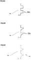
- the shape of the protrusions of the press fitting section 56c may have rectangular-shape protrusions and recesses whose upper and lower surfaces are planes perpendicular to the end surfaces of the side edge portions of the insertion section 56a. Further, as shown in FIG.6B , the shape of the protrusions of the press fitting section 56c may have a taper surface which the lower surface in gradual rises toward the upper direction toward side (right portion of FIG.6B ) . As shown in FIG.6C , the shape of the protrusions of the press fitting section 56c may have a so-called saw-tooth shape.
- two lead sections 56d are connected to the lower edge portion of the insertion section 56a in a lateral direction, in parallel. These lead sections 56d have a quadrangle cross-section viewed from an extending direction.
- the top end portions are inserted into the holes 40b which are formed on the control circuit substrate 40 as shown in FIG.3 , are soldered by a point dipping, and are performed by dust proof coating.
- the cross-section of the lead section 56d is used to the quadrangle.
- the cross-section is not limited the quadrangle, it is possible to select the shapes of a circle, a polygon or the like.
- the top end side of the lead section 56d is in parallel to a surface of the insertion section 56a, and is provided to the plane of the insertion section 56a with an offset.
- the lead section 56d is bent to a substantially thickness direction at a position with a predetermined distance in a lower direction from the lower edge side of the insertion section 56a by a bending section 56e.
- the top end of the lead section 56d is bent in parallel to the plate plane which configures to the insertion section 56a by a bending section 56f. That is, the lead section 56d is a substantially "Z"-shape viewed from the side surface of the plate.
- angles of the bending sections 56e and 56f are an obtuse angle.
- the power-supply connector terminals 56 are inserted into the power-supply connector sections 51 of the connector housing 55 from the lead section 56d side, and are held in the connector housing.
- a white arrow in FIG.7 shows an insertion direction of the connector terminals 56.
- the two connector terminals 56 are disposed in parallel in the thickness direction of the insertion section 56a and are contained in the power-supply connector section 51 of the connector housing 55.
- the connector terminals 56 are disposed such that the offset direction of the lead sections 56d is a central side of the connector housing 55 against a fixed point to the insertion section 56a of the lead section 56d.
- it is possible to miniaturize the installing section to the substrate of the connector by disposing the top end position of the lead sections 56d to the central side of connector housing 55 in this way.
- FIG.8 is a perspective view showing the connector 50 viewed from a bottom surface side of the connector housing 55 in a state that the connector terminals 56 are inserted into the connector housing 55.
- the connector housing 55 includes holes 57 for the two connector terminals. That is, at least power-supply connector terminal 56 has two lead sections 56d, and the holes 57 having two openings 57a that top end sides of the two lead sections 56d to be able to penetrate are provided in the connector housing 55.
- the lead sections 56d are protruded from the holes 57 in a perpendicular direction to the bottom surface of the connector housing 55.
- FIG.9 is a plane view showing a shape of the holes 57.
- FIG. 9A shows the shape of the hole at an inlet portion of a side which press-fits the connector terminals 56
- FIG.9B shows the shape of the holes at an outlet portion side.
- the inlet portion side of the holes 57 is corresponding to a cross-sectional shape of the plane section 56a of the connector terminal 56 and the lead sections 56d, and is a hole that has a shape which two protrusions are existed in a plane view.
- One of the holes 57 comprises two openings (through holes) 57a that the lead sections 56d penetrate, and an opening (press fitting hole) 57b that the press fitting section 56c is press-fitted.
- the openings 57a are the same as or slightly smaller than the external form of the lead sections 56d when the connector terminal 56 is shown from the press fitting direction.
- the inlet portion side of the holes 57 perfectly fits a size that the lead sections 56d is able to penetrate from the top end side by press fitting.
- the opening 57b is just smaller than the external form of the connector terminal 56 including the press fitting section 56c viewed from the press fitting direction. Accordingly, a size of an inner peripheral surface of the holes 57 is slightly smaller than that of an outer peripheral surface of the connector terminal 56.
- the outlet portion side of the holes 57 is shown in FIG.9B . Since surroundings of the two openings (through holes) that the lead sections 56d only penetrate are surrounded by guide wall 57d which is the below-described in detail, a portion of the outlet side of the opening section 57b which the guide wall 57d is existed is blocked.
- the guide wall 57d is formed along an outer peripheral of the openings 57a at a side that the lead sections 56d only protrude during receiving the connector terminal 56 as shown in FIG.10A to FIG.10C (opposite side of the insertion side of the connector 50) .
- the guide wall 57d is formed in at least three direction which each of the lead sections 56d is surrounded (left and right directions and an offset direction of the lead sections 56d), and its height has a distance from the outer peripheral of the outlet side of the holes 57 during receiving at least the connector terminal 56 to a position beyond the bending section 56f near the top end portion of the lead sections 56d.
- FIG.10A to FIG.10C are a diagram illustrating the guide wall 57d neighborhood of the connector 50 in a state that the lead sections 56d protrude from the hole 57 of the press fitting section 56c, which has the above-described configuration, through the guide wall 57d.
- FIG.10A is a top view
- FIG.10B is a side view
- FIG.10C is a perspective view.
- the lead section 56d and the guide wall 57d are disposed such that the three side surfaces which configure to a quadrangle cross-section of the lead section 56d are directly in contact with the inner surface of the guide wall 57d.
- the area is extended from a press fitting end section 57c of the connector housing 55 that the surrounding of the press fitting section 56c of the connector terminal 56 is surrounded in the outlet side, to a positon beyond the bending section 56f toward the top end portion of the lead section 56d of the connector terminal 56.
- the sizes of the openings 57a are the same as or slightly smaller than the external form of the lead section 56d when the connector terminal 56 is viewed from the press fitting direction.
- the guide wall 57d Since the guide wall 57d has such a configuration, the guide wall 57d is incorporated with the side surface portion of the lead section 56d, and a structure that seals an interior side of the connector housing 55 from the lead section 56d, is adopted as shown in a perspective view of FIG.10C .
- FIG.11A is a diagram of the connector 50 in view from an insertion side
- FIG.11B is a cross-sectional view taken along a line A-A in FIG.11A
- FIG.11C is a cross-sectional view taken along a line B-B in FIG.11A
- the white arrows indicate the insertion direction of the connector terminal 56.
- the connector terminal 56 Since the openings 57b have a size that the stoppers 56b are impossible to penetrate, the connector terminal 56 is press-fitted into a position where the stoppers 56b strikes to the back side of the bottom surface of the connector housing 55. In this way, a positioning of the press fitting direction of the connector terminal 56 is performed. At this time, although it is possible to configure that bottom end surfaces of the press fitting sections 56c slightly protrude from the openings 57b as the above embodiment and are received in the press fitting end sections 57c, it is also possible to configure that the bottom end surfaces of the press fitting sections 56c do not protrude without providing the press fitting end sections 57c.
- the guide walls 57d are disposed between the lead sections 56d such that the guide walls 57d are in contact with the lead sections 56d at the right and left sides. Further, as shown in FIG.11C , the guide walls 57d are disposed at the offset side of the lead sections 56d against a plane of the insertion section 56a from the surroundings of the openings 57a to the bending sections 56f of the top end sides of the lead sections 56d to be tightly in contact with the lead sections 56d in the vicinity of at least top end portion of the bending section 56f.
- the outlet sides of the openings 57a are blocked by the lead section 56d and the guide walls 57d so as to put on a cap. In this way, the openings 57a are sealed, and it is possible to prevent from entering the foreign matter from the connector insertion side to the substrate 40. Further, by constructing such a configuration, since the openings 57a and the opening 57b of the holes 57 are continuously formed from an opening of the power-supply connector section 51 which is formed opposite to the connector housing 55, a mold design of the connector housing 55 is also relatively easier.
- seal lip sections 58 which stand from the peripheral of the openings in order to penetrate the lead sections 56d of the connector terminal 56 from the connector 50 for electric power and signal maybe provided at a top end portion 57e of the guide walls 57d.
- FIG.12A to FIG.12D are diagrams illustrating an example, which is provided with the seal lip sections 58 at the top end portion 57e of the guide walls 57d in the vicinity of the guide walls 57d of the connector 50.
- FIG.12A is a top view
- FIG.12B is a side view
- FIG.12C is a perspective view
- FIG.12D is a cross-sectional view taken along a line X-X in FIG.12C .
- the seal lip sections 58 stand from the peripheral of the openings of the top end portions 57e of the guide walls 57d, and cover three side surfaces of the lead section 56d protruded from the top end portion 57e of the guide walls 57d (the surface S of the back surface side to the offset direction side of the lead section 56d and both side surrounding surfaces) at the top end portion of the guide walls 57d.
- the seal lip sections 58 comprise a flexible synthetic resin, elastomer or the like which have an electrical insulation, a heat conductivity and flexibility.
- the seal lip sections 58 are attached to the three side surfaces of the lead section 56d and the top end portion of the guide walls 57d.
- a size of a penetrating portion of the lead section 56d of the seal lip section 58 is smaller than the outer peripheral of the lead 56d.
- the seal lip may be adhered at the top end portion 57e of the guide walls 57d by using an adhesive or the like, or may be adhered by a self-fusing material such as the elastomer. Further, the material of the seal lip may be permeated from the peripheral of the opening of the top end portion 57e to a space of the guide wall 57d, and then may be stood from the peripheral of the opening.
- the inner surface of the seal lip section 58 is tightly in contact with the side surfaces of the lead section 56d which protrude from the top end portion 57e of the guide walls 57d. It is possible to further improve the sealing from the connector housing 55 side to the substrate 40 in comparison with a case that the guide walls 57d are only provided. Since the seal lip section 58 is formed by the material such as the synthetic resin, it is possible to maintain elasticity and to keep the sealing property after the connector press-fitting.
- the connector terminal 56 which the bending process is previously performed to the lead section 56d is able to outsert-mold to the connector housing 55, and it is possible to relatively and easily assemble the connector 50 in the low cost.
- the openings 57a, which the lead section 56d penetrates by the press-fitting, are disposed in the connector housing 55, it is possible to insert the connector terminal 56 from the lead section 56d side to the inserting direction of the connecting terminal from the external connecting apparatus. Thus, it is possible to prevent from the pulling out of the terminal due to the load from the connecting terminal inserting side, and the load to the substrate.
- the lead section 56d By performing the bending process to the lead section 56d, it is possible to reduce the stress to the substrate and the soldering portion due to the thermal contraction and the thermal expansion.
- the lead section 56d provides the bending sections 56e and 56f which are bent in two-step from the outer side of the connector housing 55 to a central direction, the top end position of the lead section 56d is able close to the adjacent communication connector section 52 and then the installing section to the substrate 40 of the connector 50 is compact.
- the stoppers 56b are disposed on the connector terminal 56 and the stoppers 56b are struck when the connector terminal 56 is inserted from the connector inserting direction, it is possible to position the press fitting direction of the connector terminal 56 by the stoppers 56b as well as that the connector terminal 56 does not directly transmit the load toward the substrate when receiving the insertion load of the connector or a pushing force (an external force) to the connector terminal 56.
- the stoppers 56b are disposed on the side edge sections of plate-shape insertion section 56a, it is hard that the connector terminal 56 buckles.
- the press fitting sections 56c having the minute protrusions are disposed on the connector terminal 56, and the connector terminal 56 is press fitted and is fixed to the connector housing 55.
- the press fitting sections 56c have a shape as shown in FIG.6B , and the structure that the connector terminal 56 is easily press-fitted and is hardly pulled out, is obtained.
- the lead section 56d is outsert-molded to the connector housing 55 after the performance of the bending process to the lead section 56d, it is not necessary to prepare extra equipment performing the bending process and it is possible to improve a process precision in comparison with a case that the bending process is performed after the outsert-mold.
- the lead section 56d being previously bent, since the stress to the resin which generates in the bending process after the outsert is reduced, an occurrence of cracks on the connector 50 is prevented.
- a bending dimension and a length dimension are previously regulated and a press fitting depth of the connector terminal 56 is determined by the stoppers 56b, a positioning precision of the top end of the lead section is improved.
- the guide walls 57d mutually and tightly in contact with the side surfaces of the lead section 56d along an outer peripheral of the openings 57a, the through holes of the lead section 56d are sealed and the sealing structure which prevents from entering the foreign matter from the connector housing side to the substrate, is adopted.
- the sealing structure which prevents from entering the foreign matter from the connector housing side to the substrate.
- FIG. 13A to FIG. 13C are diagrams illustrating another embodiments of the guide walls 57d and the hole 57
- FIG.13A and FIG.13B are perspective views
- FIG. 13C is a side view.
- the guide walls 57d may be in contact with four side surfaces (all of side surfaces) of the lead section 56d along the outer peripheral of the openings 57a.
- the fourth side surface S' as well as the other three side surfaces, fits to the lead section 56d in pressing.
- heights of the above three surfaces of the four side surfaces are those of the bending section 56f toward the top end portion of the lead section 56d from the outlet side of the hole 57.
- a height of the other one surface may be that of the bending section 56e toward the opening 57a of the connector 50.
- the shape of the inlet side of the hole 57 which is formed on the connector housing 55, has two protrusions in the plane view.
- FIG.9B the shape of the outlet side which the hole 57 is divided by the guide wall is explained.
- the opening 57b which the press fitting section 56c of the connector terminal 56 is press-fitted is blocked as shown in FIG.13B and FIG.13C which is a side view of the lead side, and the sealing property may further be improved.
- the guide wall 57d is extended to the bending section 56e in the lead section 56d of the insertion section 56e side of the connector terminal 56.
- the guide wall 57d is in contact with the four side surfaces of the lead section 56d, as shown in FIG.14A to FIG.14C , it is possible that the seal lip sections 58 is provided on the top end portion 57e of the guide wall 57d.
- FIG.14A to FIG.14C are diagrams illustrating a configuration example, which the seal lip sections 58 are provided on the top end portion 57e of the guide wall 57d
- FIG.14A is a perspective view
- FIG.14B is a side view
- FIG.14C is a top view viewed from the lead side.
- the seal lip sections 58 are stood from the peripherals of the openings of the top end portion 57e of the guide wall 57d, and cover the four side surfaces of the lead sections 56d which are protruded from the top end portion 57e of the guide wall 57d.
- the guide wall 57d is in contact with the four side surfaces of the lead section 56d (all of side surfaces) along the outer peripheral of the openings 57a. It is possible that the seal lip sections 58 further cover the four overall contact surfaces and the top end portion 57e of the guide wall to the substrate direction.
- the seal lip sections comprise a flexible synthetic resin, elastomer or the like which have electrical insulation, heat conductivity and flexibility. The seal lip sections are attached to the four side surfaces of the lead section and the top end portion 57e of the guide wall.
- the seal lip covers the four side surfaces of the lead section 56d which protrudes from the peripheral of the opening of the top end portion 57e of the guide wall 57d, the penetrate portion of the lead 56d in the seal lip portion 58 is formed smaller than the outer dimension of the lead 56d.
- the seal lip may be adhered at the top end portion 57e of the guide wall 57d by using the adhesive or the like, or may be adhered by a self fusing material such as the elastomer. Further, the material of the seal lip may be permeated from the peripheral of the opening of the top end portion 57e to a space of the guide wall 57d, and then may be stood from the peripheral of the opening.
- seal lip sections 58 are provided in such a way, it is possible that the sealing from the connector housing 55 side to the substrate 40 is further improved in a case that the guide wall 57d is only provided.
- seal lip sections 58 are formed from a material such as the synthetic resin, it is possible that elasticity is maintained and sealing property is kept after press-fitted the connector.
- the connector housing 55 is composed of the synthetic resin including a heat conductive material and the like.
- the connector housing 55 is made from such a heat conductive resin, in particular, a high heat conductive resin, by a synergy action that the lead section 56d of the connector terminal 56 is directly in contact with the guide wall 57d, heat transmission efficiency is enhanced due to the connector housing 55. Heat dissipation from the connector terminal 56 enables to be further efficiently performed via the connector housing.
- the connector in accordance with the present invention it is possible that an assembling the connector terminal to the connector housing is simplified, the lead section protruded from the connector housing is protected and prevention from entering the foreign matter from the connector to the connector housing inside can effectively be realized.
- the present invention is extremely useful.
Landscapes
- Engineering & Computer Science (AREA)
- Manufacturing & Machinery (AREA)
- Connector Housings Or Holding Contact Members (AREA)
- Coupling Device And Connection With Printed Circuit (AREA)
Claims (8)
- Connecteur, comprenant :une borne de connecteur (56) ayant une section d'insertion (56a) incluant une garniture métallique de borne pour assurer la connexion électrique à une borne de connexion externe, et une section de conducteur (56d) qui présente une première extrémité fixée à une partie d'extrémité de ladite section d'insertion (56a), présente une seconde extrémité pouvant se connecter à un substrat, et présente une forme courbée ; etun logement de connecteur (55) pour maintenir ladite borne de connecteur (56),dans lequel ledit logement de connecteur (55) comprend :un trou traversant (57a) ayant une taille minimale qui permet à ladite section de conducteur (56d) de pénétrer par insertion de ladite borne de connecteur (56), qui est pourvue de ladite section de conducteur (56d), à partir d'un côté d'insertion d'une borne de connexion externe dudit logement de connecteur (55) ; etune paroi de guidage (57d) qui est formée le long d'une périphérie externe dudit trou traversant (57a), et fait saillie dans une direction dans laquelle ladite section de conducteur (56d) fait saillie à partir dudit logement de connecteur (55),dans lequel ladite paroi de guidage (57d) a une hauteur proche d'un côté d'extrémité supérieure de ladite section de conducteur (56d) dans une section de courbure (56e, 56f) de ladite section de conducteur (56d) à partir d'au moins ladite périphérie externe dudit trou traversant (57a) dans un état où ledit logement de connecteur (55) maintient ladite borne de connecteur (56),dans lequel dans des parois internes de ladite paroi de guidage (57d) et des surfaces latérales de ladite section de conducteur (56d), moyennant quoi au moins une surface desdites parois internes de ladite paroi de guidage (57d) est mutuellement et directement en contact avec une surface latérale de ladite section de conducteur (56d) et deux autres surfaces desdites parois internes de ladite paroi de guidage (57d) sont mutuellement et directement en contact avec lesdites surfaces latérales de ladite section de conducteur (56d) sur une hauteur proche d'un côté d'extrémité supérieure de ladite section de conducteur (56d) dans une section de courbure (56e, 56f) de ladite section de conducteur (56d), une structure d'étanchéité est formée à partir de ladite section de courbure (56e, 56f) de ladite section de conducteur (56d) vers un intérieur dudit logement de connecteur (55),dans lequel ladite section de conducteur (56d) a une forme en coupe quadrangulaire, ladite partie d'extrémité supérieure de ladite section de conducteur (56d) coïncide avec une direction d'insertion vers ledit logement de connecteur (55) de ladite borne de connecteur (56) dans un état de maintien par rapport audit logement de connecteur (55), ladite section de conducteur (56d) comprend deux sections de courbure (56e, 56f), présente une forme sensiblement en « Z » et est prolongée jusqu'à une position qui est décalée vers une position centrale dudit logement de connecteur (55) par rapport à un point fixe à ladite section d'insertion (56a), et ladite paroi de guidage (57d) est en contact avec au moins trois surfaces latérales de ladite section de conducteur (56d) dont la forme en coupe est une forme quadrangulaire,dans lequel une section de lèvre d'étanchéité (58) est pourvue de sorte à se dresser à partir d'une périphérie d'une ouverture d'une partie d'extrémité supérieure (57e) de ladite paroi de guidage (57d), et une propriété d'étanchéité est améliorée par mise en contact d'une surface interne de ladite section de lèvre d'étanchéité (58) avec ladite surface latérale de ladite section de conducteur (56d), etdans lequel ladite section de lèvre d'étanchéité (58) se dresse à partir de la périphérie de l'ouverture de la partie d'extrémité supérieure (57e) de la paroi de guidage (57d) et couvre trois surfaces latérales de la section de conducteur (56d) en saillie à partir de la partie d'extrémité supérieure (57e) de la paroi de guidage (57d).
- Connecteur selon la revendication 1, dans lequel la section de lèvre d'étanchéité (58) se dresse à partir de la périphérie de l'ouverture de la partie d'extrémité supérieure (57e) de la paroi de guidage (57d) et couvre quatre surfaces latérales de la section de conducteur (56d) en saillie à partir de la partie d'extrémité supérieure (57e) de la paroi de guidage (57d).
- Connecteur selon la revendication 2, dans lequel ladite section de lèvre d'étanchéité (58) est en outre collée au niveau de la partie d'extrémité supérieure (57e) de la paroi de guidage (57d).
- Connecteur selon l'une quelconque des revendications 1 à 3, dans lequel ledit logement de connecteur (55) inclut un trou d'ajustement par pression dans lequel est ajusté par pression ladite borne de connecteur (56), et ladite section d'insertion (56a) inclut une section d'ajustement par pression qui ajuste par pression ledit côté d'extrémité fixé de ladite section de conducteur (56d) dans ledit trou d'ajustement par pression.
- Connecteur selon l'une quelconque des revendications 1 à 4, dans lequel ladite section d'ajustement par pression inclut de minuscules saillies qui font saillie à partir de sections d'extrémité latérales de ladite section d'insertion (56a) vers des directions latérales.
- Connecteur selon l'une quelconque des revendications 1 à 5, dans lequel ladite partie d'insertion (56a) est pourvue de manière adjacente à ladite section d'ajustement par pression opposée audit côté fixé de ladite section de conducteur (56d), et comprend des butées qui font saillie à partir d'une périphérie externe dudit trou d'ajustement par pression vers une direction latérale.
- Connecteur selon l'une quelconque des revendications 1 à 6, dans lequel ladite garniture métallique de borne est une borne de connexion qui est utilisée pour l'alimentation électrique et a une forme de plaque plane.
- Connecteur selon l'une quelconque des revendications 1 à 7, dans lequel ledit connecteur est constitué d'une résine thermoconductrice.
Applications Claiming Priority (2)
| Application Number | Priority Date | Filing Date | Title |
|---|---|---|---|
| JP2015022559 | 2015-02-06 | ||
| PCT/JP2016/053465 WO2016125883A1 (fr) | 2015-02-06 | 2016-02-05 | Connecteur |
Publications (3)
| Publication Number | Publication Date |
|---|---|
| EP3255736A1 EP3255736A1 (fr) | 2017-12-13 |
| EP3255736A4 EP3255736A4 (fr) | 2018-10-31 |
| EP3255736B1 true EP3255736B1 (fr) | 2020-01-08 |
Family
ID=56564221
Family Applications (1)
| Application Number | Title | Priority Date | Filing Date |
|---|---|---|---|
| EP16746714.1A Active EP3255736B1 (fr) | 2015-02-06 | 2016-02-05 | Connecteur avec étanchéité |
Country Status (5)
| Country | Link |
|---|---|
| US (1) | US10062983B2 (fr) |
| EP (1) | EP3255736B1 (fr) |
| JP (3) | JP6137426B2 (fr) |
| CN (1) | CN107210559B (fr) |
| WO (1) | WO2016125883A1 (fr) |
Families Citing this family (11)
| Publication number | Priority date | Publication date | Assignee | Title |
|---|---|---|---|---|
| US10279928B2 (en) * | 2015-08-26 | 2019-05-07 | The Boeing Company | Delta offset based surface modeling |
| DE102017222999B4 (de) * | 2017-12-18 | 2021-10-21 | Robert Bosch Gmbh | Sensoreinrichtung für ein Lenksystem eines Fahrzeugs |
| JP7017987B2 (ja) * | 2018-06-13 | 2022-02-09 | ホシデン株式会社 | コネクタアッセンブリ、接続モジュール及び接続モジュールの製造方法 |
| JP6936203B2 (ja) * | 2018-10-23 | 2021-09-15 | 矢崎総業株式会社 | 端子台、三連端子台、及び車載機器 |
| JP7253354B2 (ja) * | 2018-10-31 | 2023-04-06 | モレックス エルエルシー | コネクタ |
| US11268376B1 (en) | 2019-03-27 | 2022-03-08 | Acuity Technical Designs, LLC | Downhole safety switch and communication protocol |
| DE102020110355A1 (de) * | 2019-04-17 | 2020-10-22 | Steering Solutions Ip Holding Corporation | Anschlussklinge für header-baugruppe |
| CN111916952B (zh) * | 2019-05-10 | 2022-08-26 | 香港商安费诺(东亚)有限公司 | 具有导引及让位对接结构的壳体的连接器插座 |
| US11619119B1 (en) | 2020-04-10 | 2023-04-04 | Integrated Solutions, Inc. | Downhole gun tube extension |
| JP7609526B2 (ja) * | 2021-07-29 | 2025-01-07 | パナソニックオートモーティブシステムズ株式会社 | 部品間接続構造、電力変換装置及び部品間接続方法 |
| CN116256735A (zh) * | 2022-09-08 | 2023-06-13 | 同致电子科技(厦门)有限公司 | 超声波雷达的外壳、超声波雷达及其组装方法 |
Family Cites Families (13)
| Publication number | Priority date | Publication date | Assignee | Title |
|---|---|---|---|---|
| JPH08124622A (ja) | 1994-10-24 | 1996-05-17 | Natl House Ind Co Ltd | 差込みプラグ |
| JPH09232024A (ja) | 1996-02-19 | 1997-09-05 | Hitachi Ltd | 差込プラグ |
| JP2006140113A (ja) | 2004-11-15 | 2006-06-01 | Omron Corp | 電子機器 |
| JP3113104U (ja) * | 2005-05-18 | 2005-09-02 | 建通精密工業股▲ひん▼有限公司 | 防水強化の絶縁端子 |
| US20100224386A1 (en) * | 2006-12-18 | 2010-09-09 | Tam-Lim Oh | Electronic parts |
| JP5638932B2 (ja) | 2010-12-21 | 2014-12-10 | 矢崎総業株式会社 | 電子部品内蔵コネクタ |
| DE102011121133A1 (de) * | 2011-12-13 | 2013-06-13 | Kostal Kontakt Systeme Gmbh | Fluiddichte Kontaktdurchführung |
| JP2013206969A (ja) * | 2012-03-27 | 2013-10-07 | Keihin Corp | 電子装置 |
| DE102012104680A1 (de) * | 2012-05-30 | 2013-12-05 | Tyco Electronics Amp Gmbh | Elektrisches Steckerelement mit selbstabdichtender Kontaktaufnahme und Kontaktelement hierfür |
| US9099800B2 (en) * | 2012-11-09 | 2015-08-04 | Nsk Ltd. | Connector |
| CN104937780B (zh) * | 2013-02-06 | 2017-05-03 | 日本精工株式会社 | 多极连接器 |
| JP5590176B2 (ja) * | 2013-03-29 | 2014-09-17 | 日立金属株式会社 | 接続構造 |
| CN105073555B (zh) * | 2013-04-05 | 2016-12-28 | 日本精工株式会社 | 马达控制装置及其制造方法 |
-
2016
- 2016-02-05 WO PCT/JP2016/053465 patent/WO2016125883A1/fr not_active Ceased
- 2016-02-05 EP EP16746714.1A patent/EP3255736B1/fr active Active
- 2016-02-05 US US15/545,042 patent/US10062983B2/en active Active
- 2016-02-05 JP JP2016573429A patent/JP6137426B2/ja active Active
- 2016-02-05 CN CN201680008602.9A patent/CN107210559B/zh active Active
-
2017
- 2017-04-27 JP JP2017088599A patent/JP6288351B2/ja active Active
-
2018
- 2018-02-07 JP JP2018019872A patent/JP6489248B2/ja active Active
Non-Patent Citations (1)
| Title |
|---|
| None * |
Also Published As
| Publication number | Publication date |
|---|---|
| EP3255736A1 (fr) | 2017-12-13 |
| JP6489248B2 (ja) | 2019-03-27 |
| JPWO2016125883A1 (ja) | 2017-05-25 |
| CN107210559A (zh) | 2017-09-26 |
| JP6137426B2 (ja) | 2017-05-31 |
| US10062983B2 (en) | 2018-08-28 |
| WO2016125883A1 (fr) | 2016-08-11 |
| CN107210559B (zh) | 2019-04-12 |
| JP6288351B2 (ja) | 2018-03-07 |
| JP2017143080A (ja) | 2017-08-17 |
| JP2018101634A (ja) | 2018-06-28 |
| US20180019529A1 (en) | 2018-01-18 |
| EP3255736A4 (fr) | 2018-10-31 |
Similar Documents
| Publication | Publication Date | Title |
|---|---|---|
| EP3255736B1 (fr) | Connecteur avec étanchéité | |
| EP3477776B1 (fr) | Composant de connexion de borne, et structure de connexion de borne l'utilisant pour connecter un dispositif de commande et un moteur | |
| EP2982570B1 (fr) | Dispositif de commande de moteur et procédé de production associé | |
| EP2919328B1 (fr) | Connecteur | |
| US20090267430A1 (en) | Electric power steering apparatus | |
| US8530759B2 (en) | Electronic apparatus | |
| EP3313157A1 (fr) | Dispositif de commande électronique imperméable à l'eau | |
| JP5943098B2 (ja) | 多極コネクタ | |
| US10931046B2 (en) | Circuit device | |
| JP4998193B2 (ja) | 電気接続箱 | |
| JP7832803B2 (ja) | 接着された接続ボックスを有するステアリングコンピュータ | |
| JP2021064500A (ja) | 基板接続構造 | |
| JP2017117728A (ja) | ワイヤハーネスの端子接続構造 |
Legal Events
| Date | Code | Title | Description |
|---|---|---|---|
| STAA | Information on the status of an ep patent application or granted ep patent |
Free format text: STATUS: THE INTERNATIONAL PUBLICATION HAS BEEN MADE |
|
| PUAI | Public reference made under article 153(3) epc to a published international application that has entered the european phase |
Free format text: ORIGINAL CODE: 0009012 |
|
| STAA | Information on the status of an ep patent application or granted ep patent |
Free format text: STATUS: REQUEST FOR EXAMINATION WAS MADE |
|
| 17P | Request for examination filed |
Effective date: 20170804 |
|
| AK | Designated contracting states |
Kind code of ref document: A1 Designated state(s): AL AT BE BG CH CY CZ DE DK EE ES FI FR GB GR HR HU IE IS IT LI LT LU LV MC MK MT NL NO PL PT RO RS SE SI SK SM TR |
|
| AX | Request for extension of the european patent |
Extension state: BA ME |
|
| RIN1 | Information on inventor provided before grant (corrected) |
Inventor name: OSAKABE, TADAYOSHI Inventor name: MIYOSHI, OSAMU Inventor name: MORIMOTO, MASAKAZU |
|
| DAV | Request for validation of the european patent (deleted) | ||
| DAX | Request for extension of the european patent (deleted) | ||
| A4 | Supplementary search report drawn up and despatched |
Effective date: 20181001 |
|
| RIC1 | Information provided on ipc code assigned before grant |
Ipc: H01R 13/52 20060101AFI20180925BHEP Ipc: H01R 12/58 20110101ALI20180925BHEP Ipc: H01R 13/41 20060101ALI20180925BHEP |
|
| GRAP | Despatch of communication of intention to grant a patent |
Free format text: ORIGINAL CODE: EPIDOSNIGR1 |
|
| STAA | Information on the status of an ep patent application or granted ep patent |
Free format text: STATUS: GRANT OF PATENT IS INTENDED |
|
| INTG | Intention to grant announced |
Effective date: 20190930 |
|
| GRAS | Grant fee paid |
Free format text: ORIGINAL CODE: EPIDOSNIGR3 |
|
| GRAA | (expected) grant |
Free format text: ORIGINAL CODE: 0009210 |
|
| STAA | Information on the status of an ep patent application or granted ep patent |
Free format text: STATUS: THE PATENT HAS BEEN GRANTED |
|
| AK | Designated contracting states |
Kind code of ref document: B1 Designated state(s): AL AT BE BG CH CY CZ DE DK EE ES FI FR GB GR HR HU IE IS IT LI LT LU LV MC MK MT NL NO PL PT RO RS SE SI SK SM TR |
|
| REG | Reference to a national code |
Ref country code: GB Ref legal event code: FG4D |
|
| REG | Reference to a national code |
Ref country code: CH Ref legal event code: EP |
|
| REG | Reference to a national code |
Ref country code: IE Ref legal event code: FG4D |
|
| REG | Reference to a national code |
Ref country code: DE Ref legal event code: R096 Ref document number: 602016027862 Country of ref document: DE |
|
| REG | Reference to a national code |
Ref country code: AT Ref legal event code: REF Ref document number: 1223844 Country of ref document: AT Kind code of ref document: T Effective date: 20200215 |
|
| REG | Reference to a national code |
Ref country code: NL Ref legal event code: MP Effective date: 20200108 |
|
| REG | Reference to a national code |
Ref country code: LT Ref legal event code: MG4D |
|
| PG25 | Lapsed in a contracting state [announced via postgrant information from national office to epo] |
Ref country code: NO Free format text: LAPSE BECAUSE OF FAILURE TO SUBMIT A TRANSLATION OF THE DESCRIPTION OR TO PAY THE FEE WITHIN THE PRESCRIBED TIME-LIMIT Effective date: 20200408 Ref country code: RS Free format text: LAPSE BECAUSE OF FAILURE TO SUBMIT A TRANSLATION OF THE DESCRIPTION OR TO PAY THE FEE WITHIN THE PRESCRIBED TIME-LIMIT Effective date: 20200108 Ref country code: FI Free format text: LAPSE BECAUSE OF FAILURE TO SUBMIT A TRANSLATION OF THE DESCRIPTION OR TO PAY THE FEE WITHIN THE PRESCRIBED TIME-LIMIT Effective date: 20200108 Ref country code: PT Free format text: LAPSE BECAUSE OF FAILURE TO SUBMIT A TRANSLATION OF THE DESCRIPTION OR TO PAY THE FEE WITHIN THE PRESCRIBED TIME-LIMIT Effective date: 20200531 Ref country code: LT Free format text: LAPSE BECAUSE OF FAILURE TO SUBMIT A TRANSLATION OF THE DESCRIPTION OR TO PAY THE FEE WITHIN THE PRESCRIBED TIME-LIMIT Effective date: 20200108 Ref country code: NL Free format text: LAPSE BECAUSE OF FAILURE TO SUBMIT A TRANSLATION OF THE DESCRIPTION OR TO PAY THE FEE WITHIN THE PRESCRIBED TIME-LIMIT Effective date: 20200108 |
|
| PG25 | Lapsed in a contracting state [announced via postgrant information from national office to epo] |
Ref country code: GR Free format text: LAPSE BECAUSE OF FAILURE TO SUBMIT A TRANSLATION OF THE DESCRIPTION OR TO PAY THE FEE WITHIN THE PRESCRIBED TIME-LIMIT Effective date: 20200409 Ref country code: BG Free format text: LAPSE BECAUSE OF FAILURE TO SUBMIT A TRANSLATION OF THE DESCRIPTION OR TO PAY THE FEE WITHIN THE PRESCRIBED TIME-LIMIT Effective date: 20200408 Ref country code: HR Free format text: LAPSE BECAUSE OF FAILURE TO SUBMIT A TRANSLATION OF THE DESCRIPTION OR TO PAY THE FEE WITHIN THE PRESCRIBED TIME-LIMIT Effective date: 20200108 Ref country code: SE Free format text: LAPSE BECAUSE OF FAILURE TO SUBMIT A TRANSLATION OF THE DESCRIPTION OR TO PAY THE FEE WITHIN THE PRESCRIBED TIME-LIMIT Effective date: 20200108 Ref country code: IS Free format text: LAPSE BECAUSE OF FAILURE TO SUBMIT A TRANSLATION OF THE DESCRIPTION OR TO PAY THE FEE WITHIN THE PRESCRIBED TIME-LIMIT Effective date: 20200508 Ref country code: LV Free format text: LAPSE BECAUSE OF FAILURE TO SUBMIT A TRANSLATION OF THE DESCRIPTION OR TO PAY THE FEE WITHIN THE PRESCRIBED TIME-LIMIT Effective date: 20200108 |
|
| REG | Reference to a national code |
Ref country code: CH Ref legal event code: PL |
|
| REG | Reference to a national code |
Ref country code: DE Ref legal event code: R097 Ref document number: 602016027862 Country of ref document: DE |
|
| REG | Reference to a national code |
Ref country code: BE Ref legal event code: MM Effective date: 20200229 |
|
| PG25 | Lapsed in a contracting state [announced via postgrant information from national office to epo] |
Ref country code: CZ Free format text: LAPSE BECAUSE OF FAILURE TO SUBMIT A TRANSLATION OF THE DESCRIPTION OR TO PAY THE FEE WITHIN THE PRESCRIBED TIME-LIMIT Effective date: 20200108 Ref country code: ES Free format text: LAPSE BECAUSE OF FAILURE TO SUBMIT A TRANSLATION OF THE DESCRIPTION OR TO PAY THE FEE WITHIN THE PRESCRIBED TIME-LIMIT Effective date: 20200108 Ref country code: SK Free format text: LAPSE BECAUSE OF FAILURE TO SUBMIT A TRANSLATION OF THE DESCRIPTION OR TO PAY THE FEE WITHIN THE PRESCRIBED TIME-LIMIT Effective date: 20200108 Ref country code: MC Free format text: LAPSE BECAUSE OF FAILURE TO SUBMIT A TRANSLATION OF THE DESCRIPTION OR TO PAY THE FEE WITHIN THE PRESCRIBED TIME-LIMIT Effective date: 20200108 Ref country code: SM Free format text: LAPSE BECAUSE OF FAILURE TO SUBMIT A TRANSLATION OF THE DESCRIPTION OR TO PAY THE FEE WITHIN THE PRESCRIBED TIME-LIMIT Effective date: 20200108 Ref country code: LU Free format text: LAPSE BECAUSE OF NON-PAYMENT OF DUE FEES Effective date: 20200205 Ref country code: DK Free format text: LAPSE BECAUSE OF FAILURE TO SUBMIT A TRANSLATION OF THE DESCRIPTION OR TO PAY THE FEE WITHIN THE PRESCRIBED TIME-LIMIT Effective date: 20200108 Ref country code: RO Free format text: LAPSE BECAUSE OF FAILURE TO SUBMIT A TRANSLATION OF THE DESCRIPTION OR TO PAY THE FEE WITHIN THE PRESCRIBED TIME-LIMIT Effective date: 20200108 Ref country code: EE Free format text: LAPSE BECAUSE OF FAILURE TO SUBMIT A TRANSLATION OF THE DESCRIPTION OR TO PAY THE FEE WITHIN THE PRESCRIBED TIME-LIMIT Effective date: 20200108 |
|
| PLBE | No opposition filed within time limit |
Free format text: ORIGINAL CODE: 0009261 |
|
| STAA | Information on the status of an ep patent application or granted ep patent |
Free format text: STATUS: NO OPPOSITION FILED WITHIN TIME LIMIT |
|
| REG | Reference to a national code |
Ref country code: AT Ref legal event code: MK05 Ref document number: 1223844 Country of ref document: AT Kind code of ref document: T Effective date: 20200108 |
|
| PG25 | Lapsed in a contracting state [announced via postgrant information from national office to epo] |
Ref country code: LI Free format text: LAPSE BECAUSE OF NON-PAYMENT OF DUE FEES Effective date: 20200229 Ref country code: CH Free format text: LAPSE BECAUSE OF NON-PAYMENT OF DUE FEES Effective date: 20200229 |
|
| 26N | No opposition filed |
Effective date: 20201009 |
|
| PG25 | Lapsed in a contracting state [announced via postgrant information from national office to epo] |
Ref country code: IE Free format text: LAPSE BECAUSE OF NON-PAYMENT OF DUE FEES Effective date: 20200205 Ref country code: IT Free format text: LAPSE BECAUSE OF FAILURE TO SUBMIT A TRANSLATION OF THE DESCRIPTION OR TO PAY THE FEE WITHIN THE PRESCRIBED TIME-LIMIT Effective date: 20200108 Ref country code: AT Free format text: LAPSE BECAUSE OF FAILURE TO SUBMIT A TRANSLATION OF THE DESCRIPTION OR TO PAY THE FEE WITHIN THE PRESCRIBED TIME-LIMIT Effective date: 20200108 |
|
| PG25 | Lapsed in a contracting state [announced via postgrant information from national office to epo] |
Ref country code: PL Free format text: LAPSE BECAUSE OF FAILURE TO SUBMIT A TRANSLATION OF THE DESCRIPTION OR TO PAY THE FEE WITHIN THE PRESCRIBED TIME-LIMIT Effective date: 20200108 Ref country code: BE Free format text: LAPSE BECAUSE OF NON-PAYMENT OF DUE FEES Effective date: 20200229 Ref country code: SI Free format text: LAPSE BECAUSE OF FAILURE TO SUBMIT A TRANSLATION OF THE DESCRIPTION OR TO PAY THE FEE WITHIN THE PRESCRIBED TIME-LIMIT Effective date: 20200108 |
|
| GBPC | Gb: european patent ceased through non-payment of renewal fee |
Effective date: 20200408 |
|
| PG25 | Lapsed in a contracting state [announced via postgrant information from national office to epo] |
Ref country code: GB Free format text: LAPSE BECAUSE OF NON-PAYMENT OF DUE FEES Effective date: 20200408 |
|
| PG25 | Lapsed in a contracting state [announced via postgrant information from national office to epo] |
Ref country code: TR Free format text: LAPSE BECAUSE OF FAILURE TO SUBMIT A TRANSLATION OF THE DESCRIPTION OR TO PAY THE FEE WITHIN THE PRESCRIBED TIME-LIMIT Effective date: 20200108 Ref country code: MT Free format text: LAPSE BECAUSE OF FAILURE TO SUBMIT A TRANSLATION OF THE DESCRIPTION OR TO PAY THE FEE WITHIN THE PRESCRIBED TIME-LIMIT Effective date: 20200108 Ref country code: CY Free format text: LAPSE BECAUSE OF FAILURE TO SUBMIT A TRANSLATION OF THE DESCRIPTION OR TO PAY THE FEE WITHIN THE PRESCRIBED TIME-LIMIT Effective date: 20200108 |
|
| PG25 | Lapsed in a contracting state [announced via postgrant information from national office to epo] |
Ref country code: MK Free format text: LAPSE BECAUSE OF FAILURE TO SUBMIT A TRANSLATION OF THE DESCRIPTION OR TO PAY THE FEE WITHIN THE PRESCRIBED TIME-LIMIT Effective date: 20200108 Ref country code: AL Free format text: LAPSE BECAUSE OF FAILURE TO SUBMIT A TRANSLATION OF THE DESCRIPTION OR TO PAY THE FEE WITHIN THE PRESCRIBED TIME-LIMIT Effective date: 20200108 |
|
| PGFP | Annual fee paid to national office [announced via postgrant information from national office to epo] |
Ref country code: FR Payment date: 20251231 Year of fee payment: 11 |
|
| PGFP | Annual fee paid to national office [announced via postgrant information from national office to epo] |
Ref country code: DE Payment date: 20251230 Year of fee payment: 11 |