EP3256830B1 - Multi -plate apparatus and method for checking the braking system of land vehicles with at least two axles - Google Patents
Multi -plate apparatus and method for checking the braking system of land vehicles with at least two axles Download PDFInfo
- Publication number
- EP3256830B1 EP3256830B1 EP16713986.4A EP16713986A EP3256830B1 EP 3256830 B1 EP3256830 B1 EP 3256830B1 EP 16713986 A EP16713986 A EP 16713986A EP 3256830 B1 EP3256830 B1 EP 3256830B1
- Authority
- EP
- European Patent Office
- Prior art keywords
- vehicle
- detection
- stress
- plate
- braking
- Prior art date
- Legal status (The legal status is an assumption and is not a legal conclusion. Google has not performed a legal analysis and makes no representation as to the accuracy of the status listed.)
- Active
Links
Images


Classifications
-
- G—PHYSICS
- G01—MEASURING; TESTING
- G01L—MEASURING FORCE, STRESS, TORQUE, WORK, MECHANICAL POWER, MECHANICAL EFFICIENCY, OR FLUID PRESSURE
- G01L5/00—Apparatus for, or methods of, measuring force, work, mechanical power, or torque, specially adapted for specific purposes
- G01L5/28—Apparatus for, or methods of, measuring force, work, mechanical power, or torque, specially adapted for specific purposes for testing brakes
- G01L5/288—Measuring the force necessary to rotate a braked wheel
-
- G—PHYSICS
- G01—MEASURING; TESTING
- G01M—TESTING STATIC OR DYNAMIC BALANCE OF MACHINES OR STRUCTURES; TESTING OF STRUCTURES OR APPARATUS, NOT OTHERWISE PROVIDED FOR
- G01M17/00—Testing of vehicles
- G01M17/007—Wheeled or endless-tracked vehicles
- G01M17/04—Suspension or damping
Definitions
- the present invention relates to an apparatus and a method for checking the braking system in land vehicles with rubber treaded wheels; more in particular, the apparatus for the checking of the braking system is suited to vehicles with more than two axles.
- the safety of a road vehicle depends on the control ability thereof, in particular on the ability thereof to stop, especially in emergency conditions.
- a running vehicle is braked by the force which develops between the wheels thereof and the road surface; such force is generated due to the effect of the friction developed when each wheel is in turn broken down by the (disc or drum) braking system of the vehicle.
- the braking ability of a vehicle hence depends on the correct combination of multiple elements.
- the present invention deals with the check of the correct operation of the braking system on the whole, hence with reference not only to the operation thereof in stationary conditions, but also to the actual interactions which show up with the vehicle chassis and with the ground in dynamic conditions.
- the rules provide a periodic check of the braking ability of vehicles.
- Two apparatuses currently exist for determining braking efficiency: a rollers apparatus and a platform system.
- the former of the two provides motor-driven rollers, which drive the vehicle wheels into rotation; actuating the braking system, a resistant torque is produced on the axle which drives the rollers: measuring such torque it is possible to obtain the braking force of the system.
- the latter provides floating instrumented "plates", overall referred to as platforms, wherein it is possible to measure both the vertical force applied onto the platform (action of the actual or apparent weight of the vehicle), and the horizontal force (vehicle motion and braking forces).
- the roller system has the advantage of a greater repeatability in the measuring, it is more compact and less expensive; however, it allows to perform a measuring of the braking force in an extremely "synthetic" and theoretical manner.
- a measuring of the braking force in an extremely "synthetic" and theoretical manner.
- the platform system - despite being less repeatable and also bulkier and more expensive - allows, however, to simulate in a more precise manner the dynamics of the actual braking, including the load displacement effects onto the individual wheels.
- the braking efficiency depends on the sum of the efficiencies of each individual wheel, and braking safety also depends on the correct balancing of such forces: this condition is detectable only with the platform system.
- each plate detects exclusively its own relevant axle, for which it has been suitably arranged and positioned.
- the object of the present invention is to provide a multi-platform system which allows to overcome the described problems and, in particular, to allow the check of the braking system on land vehicles with more than two wheel axles, exceeding the limits of the specific inter-axle distances.
- a checking system of a braking system consists of a plurality of detection plates, aligned according to a testing direction (that is, the motion direction of the vehicle) on two parallel paths arranged at a typical crosswise distance, equal to the average of the wheel track of the vehicles to be checked.
- Each detection plate in a way known per se, comprises an upper resting plate mounted integral with a support frame which is housed above or within a seat embedded in the reference plane (that is, the vehicle running ground).
- the upper plate hence ends flush with the reference plane or it has ascending/descending slides, so that the vehicle wheels can go thereon continuously.
- the upper surfaces of the plates must be mutually coplanar with a maximum tolerance of +/-5 mm.
- the resting surface of the plates must have a friction coefficient equal to at least 0.6 even in wet conditions.
- a connection mechanism between the plate and the frame defines a detection device of the stresses acting on the plate, for example through a suitable arrangement of strain gauges.
- each plate is furthermore configured for detecting both vertical stresses, hence mainly the weight acting on the plate, and horizontal stresses. Horizontal stresses are substantially attributable to the horizontal force generated by the vehicle, through the tyres, due to the ascending movement thereof onto the plate and of subsequent braking.
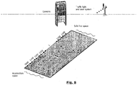
- Fig. 8 shows an exemplifying embodiment according to the invention.
- the system provides a series of detection plates, arranged continuously or preferably discontinuously (that is, two separate groups for the front array and the rear array), with a mutual distance of 5 mm.
- the illustrated system is provided for three-axle vehicles, with axle distance L + 2 metres between the first (front) axle and the second axle and an overall axle distance not exceeding X.
- the outer crosswise lane is at most of 2800 mm while the inner one is minimum of 800 mm.
- the single plates are 1100 mm long so as to be able to operate with vehicles with a minimum axle distance of 1100 mm and wheels having a maximum diameter of 1020 mm.
- the arrangement of the single detection plate is not relevant per se for the teaching of the invention. It will hence be possible to use a brake test plate of a known type, suited to detect (for example by suitably arranged load cells) the horizontal forces and the vertical forces acting thereon.
- An electronic checking unit simultaneously detects the stress signals coming from all the plates, coordinating them in an original manner with each other.
- the computing processing determines and manages this situation of change of the detection plate during the data acquisition period.
- the computing process operates by integrating the measurements detected on two (or more) subsequent plates when it is detected that an axle has moved from one plate to the other (or to multiple plates).
- this operation consists, in the simplest mode, in summing the horizontal forces detected between two subsequent plates affected by the same wheel axle during the braking space; this sum (or integration in more general terms) must hence be performed only in the condition in which the passage of the two wheels of an axle from one plate to the subsequent one is detected.
- the checking unit must determine, within the time window of the braking action (hence after the braking start instant), what are the plates from which a wheel has come off and what are the plates onto which a wheel has got on, based on the detection of the vertical stress mainly due to the vehicle weight.
- the checking unit performs a sum or integration of the horizontal stress readings detected by these two plates P n and P n+1 .
- the detection plates and the processing unit are used also for performing a check of the dampening system of the vehicle.
- a motor vehicle in order to guarantee a certain driving comfort and allow maximum adherence also in conditions of uneven roads, the wheels of a motor vehicle are not rigidly fastened to the vehicle structure, but are mounted on a suspension system.
- a motor vehicle can be modelled from a dynamic point of view as a system in which the tyre is represented by a mass connected with a spring in parallel to a dampener at the suspension; the suspension in turn is represented by a spring in parallel to a dampener (shock absorber), connected to the rigid structure of the vehicle which is provided with an own mass, the road surface makes up the stress or applied mechanic force.
- Fig.9 represents the model of a 4-wheel vehicle wherein:
- the roughness of a road prompts the suspension, through Kwheels, to vibrate; in turn Ksuspension couples the movements of the suspension with those of the vehicle body; in first approximation the suspension vibrates, uncoupling the road roughness to leave the vehicle body substantially stationary.
- the mass of the suspension, coupled through Ksuspension and Kwheels, behaves like a resonating system which has an own frequency.
- the vibration of the suspension produces a periodic change of the vertical force on the wheel: such change is highest in correspondence of the resonance frequency of the suspension.
- the suspension has a fundamental importance also in the management of the vehicle stability during a steering: the moment generated during a swerve changes the distribution of the vertical forces and hence the distribution of the same between the 4 vehicle suspensions.
- the load change on the suspensions changes the position of the mass centre of the vehicle, for example raising it, and consequently the distribution of the forces into a dangerous positive circle, reducing the vertical force on the single wheel enough to prevent the correct operation thereof.
- the detection plate system ix instead exploited to be able to provide - together with the braking information - also an important indication on the operation of the suspension system.
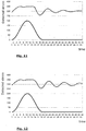
- the parameters to be acquired are the ones indicated in fig. 10 : for each wheel, the vertical force at rest Fv(i) rest , the maximum horizontal force Fh(i) max , the first two peaks of maximum vertical force Fv(i) max and Fv(i) max2 and the first two peaks of minimum vertical force Fv(i) min and Fv(i) min2 .
- the second system ( fig. 12 ) has a trend of the curve of the forces not equally effective with respect to the first system ( fig. 11 ), denouncing some operation anomaly of the suspensions.
Landscapes
- Physics & Mathematics (AREA)
- General Physics & Mathematics (AREA)
- Force Measurement Appropriate To Specific Purposes (AREA)
- Braking Arrangements (AREA)
Description
- The present invention relates to an apparatus and a method for checking the braking system in land vehicles with rubber treaded wheels; more in particular, the apparatus for the checking of the braking system is suited to vehicles with more than two axles.
- The safety of a road vehicle depends on the control ability thereof, in particular on the ability thereof to stop, especially in emergency conditions.
- A running vehicle is braked by the force which develops between the wheels thereof and the road surface; such force is generated due to the effect of the friction developed when each wheel is in turn broken down by the (disc or drum) braking system of the vehicle.
- The braking ability of a vehicle hence depends on the correct combination of multiple elements.
- the timely application of the correct action on the elements (drums or discs) which define the braking system;
- the reaction mode of the vehicle chassis and of the corresponding suspension members,
- the presence of suitable friction between the wheel and the road surface.
- The present invention deals with the check of the correct operation of the braking system on the whole, hence with reference not only to the operation thereof in stationary conditions, but also to the actual interactions which show up with the vehicle chassis and with the ground in dynamic conditions.
- The rules provide a periodic check of the braking ability of vehicles. Two apparatuses currently exist for determining braking efficiency: a rollers apparatus and a platform system. The former of the two provides motor-driven rollers, which drive the vehicle wheels into rotation; actuating the braking system, a resistant torque is produced on the axle which drives the rollers: measuring such torque it is possible to obtain the braking force of the system. The latter provides floating instrumented "plates", overall referred to as platforms, wherein it is possible to measure both the vertical force applied onto the platform (action of the actual or apparent weight of the vehicle), and the horizontal force (vehicle motion and braking forces).
- The roller system has the advantage of a greater repeatability in the measuring, it is more compact and less expensive; however, it allows to perform a measuring of the braking force in an extremely "synthetic" and theoretical manner. As a matter of fact, in a real situation, when the vehicle brakes, due to the effect of the behaviour of the chassis and of the dampeners, there is a change of the distribution of the weights which alters also the dynamics of the braking: this effect is completely neglected in the measuring performed by the rollers.
- The platform system - despite being less repeatable and also bulkier and more expensive - allows, however, to simulate in a more precise manner the dynamics of the actual braking, including the load displacement effects onto the individual wheels.
- Moreover, when a vehicle brakes on the road, the braking efficiency depends on the sum of the efficiencies of each individual wheel, and braking safety also depends on the correct balancing of such forces: this condition is detectable only with the platform system.
- A prior art example is described in
US5305636 . It relates to a system for the checking of the braking features of a vehicle, which uses resting plates with both static and dynamic weight sensors and which read vertical and horizontal forces. In the case in which the axles are more than two, it is provided that the number of plates may vary to be able to read multiple axles at the same time, but no indication is provided about how such plates must be positioned. An evolution of this system by the same inventor is described inUS5979230 : here it is provided to arrange a pair of plates at a preset distance to detect multiple axles of a long vehicle; preferred techniques are suggested which impose vehicle entry and exit speeds on the system. The axles in any case are detected individually. - None of the above-listed systems is per se capable of detecting the time relationship between the braking actions of the various axles of a vehicle, nor to distinguish the effect produced by the single axle. For such reason, these prior art systems generically provide that the wheel axles remain on the same detection plate during the braking action. In the last analysis, that limits the test speed of the vehicle and forces to build the plates sufficiently long to house the entire braking space.
- In some cases, to deal with multiple-axles vehicles, it has been explicitly suggested to use a multiple-plate system, wherein - as natural evolution of the above-said systems - a detection plate is installed for each braking wheel (see the table of
fig. 1 , which exemplifyingly refers to a two-axle vehicle andfig. 2 , which refers to a three-axle vehicle). - As in the above-said US'636 and US'230, during operation, typically each plate detects exclusively its own relevant axle, for which it has been suitably arranged and positioned.
- However, due to the large variability in the wheel base of vehicles, but especially of heavy, multiple-axles vehicles, it is impossible to build a multiple-plate system which is suitable for any type of vehicle, except a continuous path of small detection plates is defined, said plates being arranged at a close distance to each other, as contemplated in
US6481298 , which is economically burdensome. - In the table proposed in
fig. 3 , for example it is contemplated a case of a platform system with four plates in succession, which, however, is not suitable for the above-lying three-axle vehicle: as a matter of fact, it can be seen that the wheels of two axles, R1 and R3, rest on the two extreme plates P4 and P1, respectively, but the wheel of a third axle R2 rests across the two plates P4 and P3. In this circumstance, the conventional platform system would provide an incorrect reading of the braking forces. - Please notice furthermore that a punctual detection on the individual axles without the opportunity of a detection of the forces on the entire vehicle precludes the opportunity of making further considerations on the state of health of the vehicle on the whole.
- The object of the present invention is to provide a multi-platform system which allows to overcome the described problems and, in particular, to allow the check of the braking system on land vehicles with more than two wheel axles, exceeding the limits of the specific inter-axle distances.
- In particular, it is desired to obtain a detection of the forces which overall act on the entire vehicle system, to be able to obtain further indications on the general state of operation of the resting system on the ground of the vehicle, including the braking system, wheels and dampening system.
- Such objects are achieved with a multi-platform system having the features indicated in the attached main claims. The dependent claims describe other preferential features of the invention.
- Further features and advantages of the invention are in any case more evident from the following detailed description of preferred embodiments, given purely as a non-limiting example and illustrated in the attached drawings, wherein:
-
fig. 1 , as mentioned, is a prior-art platform layout, which provides the support of two wheels onto two respective plates; -
fig. 2 , as mentioned, is a similar layout to that offig. 1 which provides the support of three wheels onto three respective plates; -
fig. 3 is another prior-art platform layout, which illustrates the interaction between four plates in succession and three wheels, one of which across two plates; -
fig. 4 is a system layout according to an embodiment of the invention, employing four plates, in the initial entry-speed-measuring step; -
fig. 5 is a similar layout to that offig. 4 in an initial step of the measuring test on a three-axle vehicle; -
fig. 6 is a layout similar to that offig. 4 in the final step of the measuring test, which shows the displacement of part of the axles from one plate to the other; -
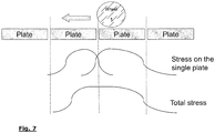
fig. 7 shows an integration diagram of measurements on an axle which, in the braking step, runs from one plate to the subsequent one; -
fig. 8 is a schematic perspective view of an exemplifying system of the invention; -
fig. 9 is a kinematic diagram of the vehicle with the dampeners and wheels thereof; -
fig. 10 is a diagram of the detected forces depending on the time in which the parameters are reported which are acquired according to a preferred embodiment of the invention; and -
figs. 11 and 12 are two diagrams relating to detection of the oscillations of the forces measured over time for an efficient system and for one in which the front dampener is inefficient, respectively. - A checking system of a braking system consists of a plurality of detection plates, aligned according to a testing direction (that is, the motion direction of the vehicle) on two parallel paths arranged at a typical crosswise distance, equal to the average of the wheel track of the vehicles to be checked.
- Each detection plate, in a way known per se, comprises an upper resting plate mounted integral with a support frame which is housed above or within a seat embedded in the reference plane (that is, the vehicle running ground). The upper plate hence ends flush with the reference plane or it has ascending/descending slides, so that the vehicle wheels can go thereon continuously. For such purpose, the upper surfaces of the plates must be mutually coplanar with a maximum tolerance of +/-5 mm. Preferably the resting surface of the plates must have a friction coefficient equal to at least 0.6 even in wet conditions.
- A connection mechanism between the plate and the frame defines a detection device of the stresses acting on the plate, for example through a suitable arrangement of strain gauges.
- The detection device of each plate is furthermore configured for detecting both vertical stresses, hence mainly the weight acting on the plate, and horizontal stresses. Horizontal stresses are substantially attributable to the horizontal force generated by the vehicle, through the tyres, due to the ascending movement thereof onto the plate and of subsequent braking.
- The length of these plates is fixed and is optimised, based on the average of the circulating vehicle fleet, so that:
- two adjacent axles of the vehicle can never find themselves simultaneously on the same plate;
- the number of plates, at least equal to three, is the least possible in connection with the maximum length of the vehicle to be measured, taking into account that it is necessary to "cover" also an additional length corresponding to the braking space necessary to the vehicle to stop;
- the interplate distance must not exceed a threshold value, beyond which braking conditions would be altered, because there would be a significant change of the friction coefficient of the wheel at the ground in the passage region between one plate and the other.
-
Fig. 8 shows an exemplifying embodiment according to the invention. As illustrated, the system provides a series of detection plates, arranged continuously or preferably discontinuously (that is, two separate groups for the front array and the rear array), with a mutual distance of 5 mm. The illustrated system is provided for three-axle vehicles, with axle distance L + 2 metres between the first (front) axle and the second axle and an overall axle distance not exceeding X. The outer crosswise lane is at most of 2800 mm while the inner one is minimum of 800 mm. The single plates are 1100 mm long so as to be able to operate with vehicles with a minimum axle distance of 1100 mm and wheels having a maximum diameter of 1020 mm. - The arrangement of the single detection plate is not relevant per se for the teaching of the invention. It will hence be possible to use a brake test plate of a known type, suited to detect (for example by suitably arranged load cells) the horizontal forces and the vertical forces acting thereon.
- By building a system according to these principles it is possible to check, with a single apparatus, the efficiency of the braking system of any one of the vehicles in circulation with the technical device which is set forth here in the following.
- An electronic checking unit simultaneously detects the stress signals coming from all the plates, coordinating them in an original manner with each other. The peculiar features of the system according to the invention can be better appreciated by resorting to a description of the operation method thereof.
- After having entered (manually or through automatic detection) in the checking unit the number of the wheel axles of the vehicle, the braking efficiency of which is to be measured, it is proceeded as follows:
- the vehicle is accelerated up to a preset speed at which the test is to be carried out;
- the vehicle is to run above the platform system at the test speed (
fig. 4 ), causing it to advance (direction F) until all the wheels are on the detection plates; - in this path it is detected when the wheels get onto the plates determining the instant Tl in which the value of the vertical loading force on the plate changes from a null value to a maximum value; similarly, the instant Tu in which the value of the vertical loading force on the plate changes from a maximum value to a null value indicates the instant when the wheel of that axle get off the plate; the time which elapses between the instant t0 at which the first wheel R1 gets onto a first plate P1 and the instant t1 at which said first wheel R1 gets onto the subsequent plate P2, knowing the length of the plate, allows to calculate the entry speed of the vehicle (which parameter is relevant to establish if the braking action meets rule requirements);
- since the checking unit owns the information relating to the number of axles of wheels of the vehicle, it can easily calculate what the instant ts is at which all the wheels got onto the plates, that is, when the last wheel R3 - in a three-axle vehicle - has got last onto the first plate P1 (position shown in
fig. 5 ) and the actual braking measurement acquisition can begin; optionally, at this instant ts a sound or visual signal (see traffic lights system infig. 8 ) is issued which warns the operator to begin braking; - braking is started: the actual beginning of the braking at instant tw1 is preferably determined using a suitable sensor which detects the pressure imparted onto the brake pedal, for example with a device as described in
EP2806255 in the name of the same Applicant; - the vehicle performs the braking and all the plates detect the vertical and horizontal stresses transmitted by the vehicle; during this deceleration intervention, the vehicle of course continues to move and the respective wheels move along a same plate and can also move from one plate to the other (precisely because, as stated, the plates are not arranged specifically for a single vehicle); at the end of the braking, that is, at instant tw2 when the vehicle is stationary and no significant changes of the stresses are detected any longer, the vehicle will find itself to affect some plates which are not necessarily the same as at the beginning of the braking; more precisely, with reference to
fig. 6 (where a comparison between the three axles of wheels is represented in the position at the beginning of the braking tw1 - references without superscripts - and at the end of the braking tw2 - references with superscripts), it can be noticed that wheel R3 has remained on plate P1, while wheels R2 and R1 have moved onto plates P3 and P4, respectively. - According to the invention, the computing processing, implemented in a suitable software onboard the checking unit, determines and manages this situation of change of the detection plate during the data acquisition period. In particular, in order to be able to acquire the braking stress of each axle, the computing process operates by integrating the measurements detected on two (or more) subsequent plates when it is detected that an axle has moved from one plate to the other (or to multiple plates). As schematised in
fig. 6 , this operation consists, in the simplest mode, in summing the horizontal forces detected between two subsequent plates affected by the same wheel axle during the braking space; this sum (or integration in more general terms) must hence be performed only in the condition in which the passage of the two wheels of an axle from one plate to the subsequent one is detected. Therefore the checking unit must determine, within the time window of the braking action (hence after the braking start instant), what are the plates from which a wheel has come off and what are the plates onto which a wheel has got on, based on the detection of the vertical stress mainly due to the vehicle weight. In all the cases in which, in the braking time window tw1 - tw2, a plate Pn has undergone a marked reduction of vertical stress and a subsequent plate Pn+1 has undergone at least a significant increase of the vertical stress, the checking unit performs a sum or integration of the horizontal stress readings detected by these two plates Pn and Pn+1. - Summing up, the processing of the data implemented in the checking unit provides to:
- detect when a first axis R1 of the vehicle gets onto a first plate P1; that is performed using the vertical force measurement,
- checking the time necessary for the weight to shift onto the second plate P2, thereby calculating the entry speed of the vehicle;
- determining, based on the piece of data of the number of axles, when all the axles have got on to the measurement system; due to the fact that the length of the plates is smaller than the minimum distance between the axles, it is possible to ascertain the above-said condition counting how many times the vertical force of the previous axle has temporarily dropped to zero, before increasing again due to the weight of the subsequent axle;
- when all the axles have got onto the measurement system, possibly activating a signal which prompts the operator to begin braking;
- establishing that the vehicle has not already begun braking while it is still getting onto the plates, detecting the horizontal component of the force for all the plates and checking that - during the step preliminary to the acquisition of the braking stresses - such force never has a component in the direction and versus opposite to the direction of the progress motion of the vehicle (vice versa, it is possible that there is a force component in the versus of the motion of the vehicle due to the traction force, necessary for the vehicle to be able to get onto the measuring system);
- after the braking start instant, acquiring the braking stress on each plate and for each individual wheel, performing the suitable integrations - as seen further above - when it is assessed that a wheel has moved from one plate to the subsequent one.
- With the system according to the invention it is hence possible to acquire the stresses transferred from the braking system of a land vehicle to the detection plates both in stationary conditions and in dynamic conditions, in a wide range of axle configurations of the vehicles. Thereby a more realistic detection is obtained of the behaviour of the braking system, since it is possible to measure both the stationary effects (forces) and the dynamic effects (for example activation delays on the various axles, load transfer, inertial forces).
- Due to the opportunity of having a dynamic detection of forces, which can be correctly allotted to each wheel axle, the opportunity opens of detecting further quantities which allow to widen the testing abilities of the system. In particular, according to the invention the detection plates and the processing unit are used also for performing a check of the dampening system of the vehicle.
- As a matter of fact, as known, in order to guarantee a certain driving comfort and allow maximum adherence also in conditions of uneven roads, the wheels of a motor vehicle are not rigidly fastened to the vehicle structure, but are mounted on a suspension system. In such respect, a motor vehicle can be modelled from a dynamic point of view as a system in which
the tyre is represented by a mass connected with a spring in parallel to a dampener at the suspension;
the suspension in turn is represented by a spring in parallel to a dampener (shock absorber), connected to the rigid structure of the vehicle which is provided with an own mass, the road surface makes up the stress or applied mechanic force. -
Fig.9 represents the model of a 4-wheel vehicle wherein: - Kwheels represents the tyre model,
- Ksuspension represents the suspension model.
- The roughness of a road prompts the suspension, through Kwheels, to vibrate; in turn Ksuspension couples the movements of the suspension with those of the vehicle body; in first approximation the suspension vibrates, uncoupling the road roughness to leave the vehicle body substantially stationary. The mass of the suspension, coupled through Ksuspension and Kwheels, behaves like a resonating system which has an own frequency. The vibration of the suspension produces a periodic change of the vertical force on the wheel: such change is highest in correspondence of the resonance frequency of the suspension.
- When the applied vertical force drops, the maximum friction force drops proportionately, reducing also the maximum braking efficiency and hence the safety of the vehicle. Also for this reason, hence, there is a significant interaction between the operation of the braking system and the behaviour of the suspension and of the tyre.
- Checking systems therefore exist which apply to the tyre a vibration of a fixed width and variable frequency, measuring the vertical force depending on the frequency, checking that the minimum force at the resonance frequency be above a set minimum.
- However, the suspension has a fundamental importance also in the management of the vehicle stability during a steering: the moment generated during a swerve changes the distribution of the vertical forces and hence the distribution of the same between the 4 vehicle suspensions. The load change on the suspensions changes the position of the mass centre of the vehicle, for example raising it, and consequently the distribution of the forces into a dangerous positive circle, reducing the vertical force on the single wheel enough to prevent the correct operation thereof.
- This feature of the suspension cannot be measured by conventional "vibration" systems indicated above.
- According to the invention, the detection plate system ix instead exploited to be able to provide - together with the braking information - also an important indication on the operation of the suspension system.
- Assuming to check a 4-wheel vehicle, it must be noticed that during braking, each wheel undergoes a braking force Fh(i) (horizontal, linked to the friction between wheel and plate) and a component of the vehicle weight Fv(i) where i = 1,2,3,4 identifies the 4 wheels (in a 4-wheel vehicle).
- With a stationary vehicle, the horizontal components are null and the vertical ones depend on the position of the mass centre of the vehicle with respect to the 4 wheels: Mg = Fv(1) + Fv(2) + Fv(3) + Fv(4). Be d(i) the vector distances (with the components x(i), y(i), z(i) in which x(i) is the distance measured along the displacement axis of the vehicle, y(i) is the distance measured in the orthogonal direction and z(i) in the vertical direction; for a vehicle on a plane it can be assumed that all the z(i) be equal to the height from the ground of the centre of gravity, h) of the 4 points of contact of the wheels with the ground with respect to the centre of gravity. Due to the different point of application of the vehicle mass Mg and of the various Fv(i), in dynamic conditions a moment Mv = d(1)*Fv(1) + d(2)*Fv(2) +d(3)*Fv(3) +d(4)*Fv(4) is generated (which is zero in stationary conditions) which is the one which determines a different distribution on the 4 wheels of the forces Fv(i). Since Fv(i) are vertical forces, hence only with a component along the Z axis, Mv has only components along axes X and Y which meet the following conditions:


- During the braking action it can be assumed that the total braking force, always applied to the mass centre, is equal to the sum of the four horizontal forces Fbraking = Fh(1) + Fh(2) + Fh(3) + Fh(4). Due to the different point of application of the Fbraking and of the various Fh(i), during braking a moment Mh = d(1)*Fh(1) + d(2)*Fh(2) +d(3)*Fh(3) +d(4)*Fh(4) is generated, which moment has three components:
- a vertically-oriented component, which tends to cause the vehicle to steer;
- a component in the direction of the motion, which tends to change the balancing of the weights between the right and left wheels;
- a component orthogonal to the direction of the motion which tends to change the balancing of the weights between front wheels and rear wheels.
- Since during braking the vehicle, which vehicle consists of the assembly of body, wheels and suspensions, must not rotate (at least until the system tolerance limits are reached, beyond which the vehicle loses control and adherence to the road), this moment is compensated by a change of the Fv(i) so that Mv + Mh = 0.
- The change of the forces applied to the suspensions produces a deformation thereof, which slightly changes the d(i) and hence further changes the attitude of the vehicle when braking.
- When the vehicle stops, the horizontal component of the forces Fh(i) drop to zero, and as such the vertical forces return to the rest value thereof; however, the suspensions have accumulated energy due to the change of the forces during braking and release this energy when the braking is over.
- As soon as Fh(i) drops to zero, the suspension begins to return towards the rest condition, instantly generating a force equal to the force which had determined the deformation thereof: such force is delivered to the support plane, hence onto the detection plates of the check system of the invention, through Kwheels (which is considered very high) and to the vehicle body, generating a coupled system of harmonic resonators (the 4 suspensions), wherein the resonance frequency depends on the vehicle mass M and on Ksuspension.
- Therefore, measuring with the system of the invention the trend of forces Fv(i), at the end of a sudden braking (that is a braking time shorter than the natural settling time of the harmonic system of vehicle plus suspension), it is possible to obtain the operation status of the suspensions.
- According to the invention, it is suggested to acquire some significant parameters during the braking test, which then allow to obtain with sufficient reliability the state of health of the suspensions of a vehicle. In particular, the parameters to be acquired are the ones indicated in
fig. 10 : for each wheel, the vertical force at rest Fv(i)rest, the maximum horizontal force Fh(i)max, the first two peaks of maximum vertical force Fv(i)max and Fv(i)max2 and the first two peaks of minimum vertical force Fv(i)min and Fv(i)min2. - With these parameters it is possible to establish a state of the suspension thus characterised:
- the forces Fh(i)max are scaled depending on the relative forces Fv(i) at rest, to determine the efficiency of each wheel;
- the ratio Fh(i)max/Fv(i)rest between the four wheels must be reasonably even, to remove the event of a wheel not braking and possibly sliding;
- the ratio Fv(i)max/Fv(i)rest is a measure of the displacement of the forces caused by moment Mh; the values referred to the wheels on the same axle must not differ by more than a few percentage units; in the contrary there is an evident sign of dissymmetry between the suspensions of the same axle;
- the ratio between (Fv(i)max - Fv(i)rest) and (Fv(i)min - Fv(i)rest) is a measure of the dampening efficiency of the suspension;
- the ratio between (Fv(i)max - Fv(i)rest) and (Fv(i)max2 - Fv(i)rest) is a measure of the dampening efficiency of the suspension.
- The comparison of the preceding parameters between the wheels of the same axle allows to check any system imbalances, which can cause dangerous overturning moments of the vehicle.
- The comparison between these parameters, obtained from the acquisitions provided by the system according to the invention, allows to obtain a measurement of the efficiency of the suspension on the whole, in connection with the road behaviour safety.
- As summarily detectable from the comparison of the two diagrams of
figs. 11 and 12 , the second system (fig. 12 ) has a trend of the curve of the forces not equally effective with respect to the first system (fig. 11 ), denouncing some operation anomaly of the suspensions. - However, it is understood that the invention must not be considered limited to the special arrangements illustrated above, which make up only exemplifying embodiments thereof, but that different variants are possible, all within the reach of a person skilled in the field, without departing from the scope of protection of the invention, as defined by the following claims.
Claims (6)
- Multi-plate system for checking the braking capacity of motor vehicles with at least two wheel axes, comprising pairs of detection plates aligned according to a motion direction on two parallel paths spaced by a distance related to the wheel track, wherein each detection plate has at least a support surface configured with detection means apt to detect horizontal (Fh(i)) and vertical (Fv(i)) components of a stress transferred by the vehicle wheels to such surface, characterised in that:- at least three pairs of aligned detection plates are provided, mutually dimensioned and spaced so as to prevent the wheels of a single axis from simultaneously resting on two pairs of detection plates and that on a same pair of detection plates the wheels of multiple axes from resting simultaneously;- a checking unit is furthermore provided which detects the development in time of said vertical (Fv(i)) and horizontal (Fh(i)) components of the stress and which determines when the wheels of an axis get on and off a single detection plate (Pn) based on the measurement peaks of said vertical component (Fv(i)) of the stress;- said checking unit has data processing means apt to integrate over time the measurements of said horizontal component (Fh(i)) of the stress on a first detection plate (Pn) and on the subsequent one (Pn+1) when it is detected, within a braking measurement time range (tw1 - tw2), that said vertical component (Fv(i)) of the stress on said first detection plate (Pn) undergoes a significant reduction and said vertical component (Fv(i)) of the stress on said subsequent detection plate (Pn+1) undergoes a significant increase.
- Multi-plate system as claimed in 1, characterised in that said data processing means are also apt to detect the time elapsed between the initial detection time (t0) of a vertical component of the stress on a first plate (P1) and an initial detection time (t1) of a vertical component of the stress on a subsequent plate (P2) for determining a vehicle entry speed in the checking system.
- Multi-plate system as claimed in 1 or 2, characterised in that said checking unit also comprises data input means by which the number (N) of vehicle axes is entered in said data processing means, so that the time is determined at which the Nth peak of vertical component of the stress is detected by a first one (P1) of said detection plates and an audible/visible signal is provided to an operator to start the braking action and the measuring time range of the braking action (tw1- tw2).
- Checking method of a braking system of a land vehicle equipped with at least two wheel axes, comprising the steps of causing a vehicle to move on a multi-plate system as claimed in any one of the previous claims and performing a detection of the vertical and horizontal components of the stresses transferred by the vehicle wheels to detection surfaces of detection plates, characterised in that:- by detecting the time difference between a peak of the vertical component (Fv(i)) of said stresses on a first detection plate (P1) and on a subsequent one (P2), the vehicle entry speed is determined on the system;- by entering the number (N) of vehicle axes, the time is determined at which the Nth peak of vertical component of the stress is detected by said first detection plate (P1) and hence the start of a measuring time range of the braking action (tw1- tw2) is determined;- the stresses on said detection plates in said measuring time range of the braking action (tw1 - tw2) are detected;- the measurements of said horizontal component of the stress (Fh(i)) on a detection plate (Pn) and on the subsequent one (Pn+1) are integrated in time when it is detected, within said measuring time range of the braking action (tw1- tw2), that said vertical component (Fv(i)) of the stress on said detection plate (Pn) undergoes a significant reduction and said vertical component (Fv(i)) of the stress on said subsequent detection plate (Pn+1) undergoes a significant increase.
- Method as claimed in 4, wherein before said measuring time range of the braking action (tw1 - tw2), said horizontal component (Fh(i)) of the stress on the multi-plate system is detected to check that it does not have components in the vehicle motion direction and of the opposite direction.
- Method as in 4 or 5, wherein for each of the vehicle wheels it is acquired
the parameter of vertical force at rest Fv(i)rest, and
during the braking time, also the parameters maximum horizontal force Fh(i)max, the first two peaks of maximum vertical force Fv(i)max and Fv(i)max2 and the first two peaks of minim vertical force Fv(i)min and Fv(i)min2
in order to subsequently determine also a state of operation of the vehicle suspension arrangement characterised by said parameters.
Applications Claiming Priority (2)
| Application Number | Priority Date | Filing Date | Title |
|---|---|---|---|
| ITVA20150002 | 2015-02-11 | ||
| PCT/IB2016/050687 WO2016128899A2 (en) | 2015-02-11 | 2016-02-10 | Multi -plate apparatus and method for checking the braking system of land vehicles with at least two axles |
Publications (2)
| Publication Number | Publication Date |
|---|---|
| EP3256830A2 EP3256830A2 (en) | 2017-12-20 |
| EP3256830B1 true EP3256830B1 (en) | 2019-12-04 |
Family
ID=52633529
Family Applications (1)
| Application Number | Title | Priority Date | Filing Date |
|---|---|---|---|
| EP16713986.4A Active EP3256830B1 (en) | 2015-02-11 | 2016-02-10 | Multi -plate apparatus and method for checking the braking system of land vehicles with at least two axles |
Country Status (3)
| Country | Link |
|---|---|
| EP (1) | EP3256830B1 (en) |
| ES (1) | ES2783648T3 (en) |
| WO (1) | WO2016128899A2 (en) |
Cited By (1)
| Publication number | Priority date | Publication date | Assignee | Title |
|---|---|---|---|---|
| EP4102200B1 (en) * | 2021-06-07 | 2023-12-27 | Vamag S.r.l. | Multi-platform system for checking the braking apparatus of land vehicles having at least two axles |
Families Citing this family (2)
| Publication number | Priority date | Publication date | Assignee | Title |
|---|---|---|---|---|
| IT201600130259A1 (en) * | 2016-12-22 | 2018-06-22 | Vamag Srl | TEST BENCH WITH VARIABLE DRAWN PLATFORMS |
| CN108020370B (en) * | 2017-12-29 | 2024-02-20 | 盘天(厦门)智能交通有限公司 | Combined type weighing platform paving structure |
Family Cites Families (3)
| Publication number | Priority date | Publication date | Assignee | Title |
|---|---|---|---|---|
| NL8304330A (en) * | 1983-12-15 | 1985-07-01 | Koni Bv | DEVICE FOR TESTING THE SHOCK ABSORBERS OF AN AUTOMOTIVE. |
| US5305636A (en) * | 1993-02-12 | 1994-04-26 | Hunter Engineering Company | Plate brake tester and method |
| US5979230A (en) * | 1997-05-20 | 1999-11-09 | Hunter Engineering Company | Brake in motion plate brake tester and method |
-
2016
- 2016-02-10 ES ES16713986T patent/ES2783648T3/en active Active
- 2016-02-10 EP EP16713986.4A patent/EP3256830B1/en active Active
- 2016-02-10 WO PCT/IB2016/050687 patent/WO2016128899A2/en not_active Ceased
Non-Patent Citations (1)
| Title |
|---|
| PANKAJ POKHRIYAL: "Automotive Design", 25 April 2012 (2012-04-25), XP055479220, Retrieved from the Internet <URL:http://web.iitd.ac.in/~achawla/public_html/736/17-brakes.pdf> [retrieved on 20180529] * |
Cited By (1)
| Publication number | Priority date | Publication date | Assignee | Title |
|---|---|---|---|---|
| EP4102200B1 (en) * | 2021-06-07 | 2023-12-27 | Vamag S.r.l. | Multi-platform system for checking the braking apparatus of land vehicles having at least two axles |
Also Published As
| Publication number | Publication date |
|---|---|
| WO2016128899A3 (en) | 2016-11-10 |
| EP3256830A2 (en) | 2017-12-20 |
| ES2783648T3 (en) | 2020-09-17 |
| WO2016128899A2 (en) | 2016-08-18 |
Similar Documents
| Publication | Publication Date | Title |
|---|---|---|
| US6257054B1 (en) | Portable roller dynamometer and vehicle testing method | |
| CN105716879B (en) | A kind of vehicle ABS check-out console with clutch | |
| US7392693B2 (en) | Test stand for motor vehicles | |
| JPH10281942A (en) | Vehicle part movement characteristic test apparatus and vehicle part movement characteristic test method | |
| CN103162905B (en) | A kind of vehicle centroid height measurement method | |
| CN101363751A (en) | Method and device for determining the load of a moving vehicle | |
| US10337936B2 (en) | Dynamometer having a chassis to chassis load measurement device | |
| EP3256830B1 (en) | Multi -plate apparatus and method for checking the braking system of land vehicles with at least two axles | |
| JPH02105023A (en) | Method and device for weighing car | |
| RU2297932C1 (en) | Methods of diagnosing condition of brake system of automobile furnished with antilocking system (versions); method of and device for diagnosing condition of automobile brake system | |
| CN103171490B (en) | Forewarning method and forewarning system of road vehicle curve side rollover | |
| CN105954542A (en) | Full-automatic automobile speed detection equipment | |
| RU2279361C1 (en) | Test stand | |
| RU2365516C1 (en) | Method to estimate vehicle braking efficiency and stability, anti-locking system serviceability and device to these effects | |
| JP2869846B2 (en) | Vehicle braking performance measurement device | |
| JP2009504483A (en) | Load sensing wheel support knuckle assembly and usage | |
| IT202100014741A1 (en) | MULTI-PLATE SYSTEM FOR CHECKING THE BRAKING SYSTEM OF LAND VEHICLES WITH AT LEAST TWO AXLES | |
| RU213401U1 (en) | Stand for monitoring the technical condition of wheeled vehicles with freewheel | |
| RU2276026C1 (en) | Test stand | |
| US12434943B2 (en) | Beam climber active brake health monitoring system | |
| Senabre et al. | Comparative analysis of various brake testers used in Ministry of Transport facilities, such as: bank of roller testers and dynamometric platform testers | |
| Muthoriq et al. | A method for measuring tire characteristic using brake tester | |
| Jilek et al. | The formation of car skid at a safe speed by reducing the radial response of car wheels | |
| CN119451874A (en) | Method for verifying the operation of at least one braking device of at least one vehicle and corresponding verification system | |
| RU2316438C1 (en) | Device for diagnosing condition of road vehicle brake system |
Legal Events
| Date | Code | Title | Description |
|---|---|---|---|
| STAA | Information on the status of an ep patent application or granted ep patent |
Free format text: STATUS: THE INTERNATIONAL PUBLICATION HAS BEEN MADE |
|
| PUAI | Public reference made under article 153(3) epc to a published international application that has entered the european phase |
Free format text: ORIGINAL CODE: 0009012 |
|
| STAA | Information on the status of an ep patent application or granted ep patent |
Free format text: STATUS: REQUEST FOR EXAMINATION WAS MADE |
|
| 17P | Request for examination filed |
Effective date: 20170908 |
|
| AK | Designated contracting states |
Kind code of ref document: A2 Designated state(s): AL AT BE BG CH CY CZ DE DK EE ES FI FR GB GR HR HU IE IS IT LI LT LU LV MC MK MT NL NO PL PT RO RS SE SI SK SM TR |
|
| AX | Request for extension of the european patent |
Extension state: BA ME |
|
| DAV | Request for validation of the european patent (deleted) | ||
| DAX | Request for extension of the european patent (deleted) | ||
| STAA | Information on the status of an ep patent application or granted ep patent |
Free format text: STATUS: EXAMINATION IS IN PROGRESS |
|
| 17Q | First examination report despatched |
Effective date: 20180604 |
|
| GRAP | Despatch of communication of intention to grant a patent |
Free format text: ORIGINAL CODE: EPIDOSNIGR1 |
|
| STAA | Information on the status of an ep patent application or granted ep patent |
Free format text: STATUS: GRANT OF PATENT IS INTENDED |
|
| INTG | Intention to grant announced |
Effective date: 20190621 |
|
| GRAS | Grant fee paid |
Free format text: ORIGINAL CODE: EPIDOSNIGR3 |
|
| GRAA | (expected) grant |
Free format text: ORIGINAL CODE: 0009210 |
|
| STAA | Information on the status of an ep patent application or granted ep patent |
Free format text: STATUS: THE PATENT HAS BEEN GRANTED |
|
| AK | Designated contracting states |
Kind code of ref document: B1 Designated state(s): AL AT BE BG CH CY CZ DE DK EE ES FI FR GB GR HR HU IE IS IT LI LT LU LV MC MK MT NL NO PL PT RO RS SE SI SK SM TR |
|
| REG | Reference to a national code |
Ref country code: GB Ref legal event code: FG4D |
|
| REG | Reference to a national code |
Ref country code: CH Ref legal event code: EP |
|
| REG | Reference to a national code |
Ref country code: AT Ref legal event code: REF Ref document number: 1209973 Country of ref document: AT Kind code of ref document: T Effective date: 20191215 |
|
| REG | Reference to a national code |
Ref country code: DE Ref legal event code: R096 Ref document number: 602016025507 Country of ref document: DE |
|
| REG | Reference to a national code |
Ref country code: IE Ref legal event code: FG4D |
|
| REG | Reference to a national code |
Ref country code: NL Ref legal event code: MP Effective date: 20191204 |
|
| REG | Reference to a national code |
Ref country code: LT Ref legal event code: MG4D |
|
| PG25 | Lapsed in a contracting state [announced via postgrant information from national office to epo] |
Ref country code: LT Free format text: LAPSE BECAUSE OF FAILURE TO SUBMIT A TRANSLATION OF THE DESCRIPTION OR TO PAY THE FEE WITHIN THE PRESCRIBED TIME-LIMIT Effective date: 20191204 Ref country code: BG Free format text: LAPSE BECAUSE OF FAILURE TO SUBMIT A TRANSLATION OF THE DESCRIPTION OR TO PAY THE FEE WITHIN THE PRESCRIBED TIME-LIMIT Effective date: 20200304 Ref country code: FI Free format text: LAPSE BECAUSE OF FAILURE TO SUBMIT A TRANSLATION OF THE DESCRIPTION OR TO PAY THE FEE WITHIN THE PRESCRIBED TIME-LIMIT Effective date: 20191204 Ref country code: SE Free format text: LAPSE BECAUSE OF FAILURE TO SUBMIT A TRANSLATION OF THE DESCRIPTION OR TO PAY THE FEE WITHIN THE PRESCRIBED TIME-LIMIT Effective date: 20191204 Ref country code: LV Free format text: LAPSE BECAUSE OF FAILURE TO SUBMIT A TRANSLATION OF THE DESCRIPTION OR TO PAY THE FEE WITHIN THE PRESCRIBED TIME-LIMIT Effective date: 20191204 Ref country code: NO Free format text: LAPSE BECAUSE OF FAILURE TO SUBMIT A TRANSLATION OF THE DESCRIPTION OR TO PAY THE FEE WITHIN THE PRESCRIBED TIME-LIMIT Effective date: 20200304 Ref country code: GR Free format text: LAPSE BECAUSE OF FAILURE TO SUBMIT A TRANSLATION OF THE DESCRIPTION OR TO PAY THE FEE WITHIN THE PRESCRIBED TIME-LIMIT Effective date: 20200305 |
|
| PG25 | Lapsed in a contracting state [announced via postgrant information from national office to epo] |
Ref country code: HR Free format text: LAPSE BECAUSE OF FAILURE TO SUBMIT A TRANSLATION OF THE DESCRIPTION OR TO PAY THE FEE WITHIN THE PRESCRIBED TIME-LIMIT Effective date: 20191204 Ref country code: RS Free format text: LAPSE BECAUSE OF FAILURE TO SUBMIT A TRANSLATION OF THE DESCRIPTION OR TO PAY THE FEE WITHIN THE PRESCRIBED TIME-LIMIT Effective date: 20191204 |
|
| PG25 | Lapsed in a contracting state [announced via postgrant information from national office to epo] |
Ref country code: AL Free format text: LAPSE BECAUSE OF FAILURE TO SUBMIT A TRANSLATION OF THE DESCRIPTION OR TO PAY THE FEE WITHIN THE PRESCRIBED TIME-LIMIT Effective date: 20191204 |
|
| PG25 | Lapsed in a contracting state [announced via postgrant information from national office to epo] |
Ref country code: EE Free format text: LAPSE BECAUSE OF FAILURE TO SUBMIT A TRANSLATION OF THE DESCRIPTION OR TO PAY THE FEE WITHIN THE PRESCRIBED TIME-LIMIT Effective date: 20191204 Ref country code: RO Free format text: LAPSE BECAUSE OF FAILURE TO SUBMIT A TRANSLATION OF THE DESCRIPTION OR TO PAY THE FEE WITHIN THE PRESCRIBED TIME-LIMIT Effective date: 20191204 Ref country code: NL Free format text: LAPSE BECAUSE OF FAILURE TO SUBMIT A TRANSLATION OF THE DESCRIPTION OR TO PAY THE FEE WITHIN THE PRESCRIBED TIME-LIMIT Effective date: 20191204 Ref country code: CZ Free format text: LAPSE BECAUSE OF FAILURE TO SUBMIT A TRANSLATION OF THE DESCRIPTION OR TO PAY THE FEE WITHIN THE PRESCRIBED TIME-LIMIT Effective date: 20191204 Ref country code: PT Free format text: LAPSE BECAUSE OF FAILURE TO SUBMIT A TRANSLATION OF THE DESCRIPTION OR TO PAY THE FEE WITHIN THE PRESCRIBED TIME-LIMIT Effective date: 20200429 |
|
| PG25 | Lapsed in a contracting state [announced via postgrant information from national office to epo] |
Ref country code: SM Free format text: LAPSE BECAUSE OF FAILURE TO SUBMIT A TRANSLATION OF THE DESCRIPTION OR TO PAY THE FEE WITHIN THE PRESCRIBED TIME-LIMIT Effective date: 20191204 Ref country code: IS Free format text: LAPSE BECAUSE OF FAILURE TO SUBMIT A TRANSLATION OF THE DESCRIPTION OR TO PAY THE FEE WITHIN THE PRESCRIBED TIME-LIMIT Effective date: 20200404 Ref country code: SK Free format text: LAPSE BECAUSE OF FAILURE TO SUBMIT A TRANSLATION OF THE DESCRIPTION OR TO PAY THE FEE WITHIN THE PRESCRIBED TIME-LIMIT Effective date: 20191204 |
|
| REG | Reference to a national code |
Ref country code: DE Ref legal event code: R097 Ref document number: 602016025507 Country of ref document: DE |
|
| REG | Reference to a national code |
Ref country code: AT Ref legal event code: MK05 Ref document number: 1209973 Country of ref document: AT Kind code of ref document: T Effective date: 20191204 |
|
| REG | Reference to a national code |
Ref country code: ES Ref legal event code: FG2A Ref document number: 2783648 Country of ref document: ES Kind code of ref document: T3 Effective date: 20200917 |
|
| REG | Reference to a national code |
Ref country code: CH Ref legal event code: PL |
|
| PLBE | No opposition filed within time limit |
Free format text: ORIGINAL CODE: 0009261 |
|
| STAA | Information on the status of an ep patent application or granted ep patent |
Free format text: STATUS: NO OPPOSITION FILED WITHIN TIME LIMIT |
|
| REG | Reference to a national code |
Ref country code: BE Ref legal event code: MM Effective date: 20200229 |
|
| PG25 | Lapsed in a contracting state [announced via postgrant information from national office to epo] |
Ref country code: LU Free format text: LAPSE BECAUSE OF NON-PAYMENT OF DUE FEES Effective date: 20200210 Ref country code: DK Free format text: LAPSE BECAUSE OF FAILURE TO SUBMIT A TRANSLATION OF THE DESCRIPTION OR TO PAY THE FEE WITHIN THE PRESCRIBED TIME-LIMIT Effective date: 20191204 Ref country code: MC Free format text: LAPSE BECAUSE OF FAILURE TO SUBMIT A TRANSLATION OF THE DESCRIPTION OR TO PAY THE FEE WITHIN THE PRESCRIBED TIME-LIMIT Effective date: 20191204 |
|
| 26N | No opposition filed |
Effective date: 20200907 |
|
| PG25 | Lapsed in a contracting state [announced via postgrant information from national office to epo] |
Ref country code: SI Free format text: LAPSE BECAUSE OF FAILURE TO SUBMIT A TRANSLATION OF THE DESCRIPTION OR TO PAY THE FEE WITHIN THE PRESCRIBED TIME-LIMIT Effective date: 20191204 Ref country code: AT Free format text: LAPSE BECAUSE OF FAILURE TO SUBMIT A TRANSLATION OF THE DESCRIPTION OR TO PAY THE FEE WITHIN THE PRESCRIBED TIME-LIMIT Effective date: 20191204 Ref country code: LI Free format text: LAPSE BECAUSE OF NON-PAYMENT OF DUE FEES Effective date: 20200229 Ref country code: PL Free format text: LAPSE BECAUSE OF FAILURE TO SUBMIT A TRANSLATION OF THE DESCRIPTION OR TO PAY THE FEE WITHIN THE PRESCRIBED TIME-LIMIT Effective date: 20191204 Ref country code: CH Free format text: LAPSE BECAUSE OF NON-PAYMENT OF DUE FEES Effective date: 20200229 |
|
| PG25 | Lapsed in a contracting state [announced via postgrant information from national office to epo] |
Ref country code: IE Free format text: LAPSE BECAUSE OF NON-PAYMENT OF DUE FEES Effective date: 20200210 |
|
| PG25 | Lapsed in a contracting state [announced via postgrant information from national office to epo] |
Ref country code: BE Free format text: LAPSE BECAUSE OF NON-PAYMENT OF DUE FEES Effective date: 20200229 |
|
| GBPC | Gb: european patent ceased through non-payment of renewal fee |
Effective date: 20200304 |
|
| PG25 | Lapsed in a contracting state [announced via postgrant information from national office to epo] |
Ref country code: GB Free format text: LAPSE BECAUSE OF NON-PAYMENT OF DUE FEES Effective date: 20200304 |
|
| PG25 | Lapsed in a contracting state [announced via postgrant information from national office to epo] |
Ref country code: TR Free format text: LAPSE BECAUSE OF FAILURE TO SUBMIT A TRANSLATION OF THE DESCRIPTION OR TO PAY THE FEE WITHIN THE PRESCRIBED TIME-LIMIT Effective date: 20191204 Ref country code: MT Free format text: LAPSE BECAUSE OF FAILURE TO SUBMIT A TRANSLATION OF THE DESCRIPTION OR TO PAY THE FEE WITHIN THE PRESCRIBED TIME-LIMIT Effective date: 20191204 Ref country code: CY Free format text: LAPSE BECAUSE OF FAILURE TO SUBMIT A TRANSLATION OF THE DESCRIPTION OR TO PAY THE FEE WITHIN THE PRESCRIBED TIME-LIMIT Effective date: 20191204 |
|
| PG25 | Lapsed in a contracting state [announced via postgrant information from national office to epo] |
Ref country code: MK Free format text: LAPSE BECAUSE OF FAILURE TO SUBMIT A TRANSLATION OF THE DESCRIPTION OR TO PAY THE FEE WITHIN THE PRESCRIBED TIME-LIMIT Effective date: 20191204 |
|
| P01 | Opt-out of the competence of the unified patent court (upc) registered |
Effective date: 20230421 |
|
| PGFP | Annual fee paid to national office [announced via postgrant information from national office to epo] |
Ref country code: ES Payment date: 20240301 Year of fee payment: 9 |
|
| PGFP | Annual fee paid to national office [announced via postgrant information from national office to epo] |
Ref country code: DE Payment date: 20240116 Year of fee payment: 9 |
|
| PGFP | Annual fee paid to national office [announced via postgrant information from national office to epo] |
Ref country code: FR Payment date: 20240116 Year of fee payment: 9 |
|
| REG | Reference to a national code |
Ref country code: DE Ref legal event code: R119 Ref document number: 602016025507 Country of ref document: DE |
|
| PG25 | Lapsed in a contracting state [announced via postgrant information from national office to epo] |
Ref country code: DE Free format text: LAPSE BECAUSE OF NON-PAYMENT OF DUE FEES Effective date: 20250902 |
|
| PG25 | Lapsed in a contracting state [announced via postgrant information from national office to epo] |
Ref country code: FR Free format text: LAPSE BECAUSE OF NON-PAYMENT OF DUE FEES Effective date: 20250228 |
|
| REG | Reference to a national code |
Ref country code: ES Ref legal event code: FD2A Effective date: 20260327 |
|
| PG25 | Lapsed in a contracting state [announced via postgrant information from national office to epo] |
Ref country code: ES Free format text: LAPSE BECAUSE OF NON-PAYMENT OF DUE FEES Effective date: 20250211 |
|
| PGFP | Annual fee paid to national office [announced via postgrant information from national office to epo] |
Ref country code: IT Payment date: 20260121 Year of fee payment: 11 |