EP3257100B2 - Dispositif de transmission de données, ligne de boucle et système de boucle - Google Patents
Dispositif de transmission de données, ligne de boucle et système de boucle Download PDFInfo
- Publication number
- EP3257100B2 EP3257100B2 EP17711591.2A EP17711591A EP3257100B2 EP 3257100 B2 EP3257100 B2 EP 3257100B2 EP 17711591 A EP17711591 A EP 17711591A EP 3257100 B2 EP3257100 B2 EP 3257100B2
- Authority
- EP
- European Patent Office
- Prior art keywords
- longitudinal slot
- data transmission
- transmission device
- slot
- hollow profile
- Prior art date
- Legal status (The legal status is an assumption and is not a legal conclusion. Google has not performed a legal analysis and makes no representation as to the accuracy of the status listed.)
- Active
Links
Images

Classifications
-
- B—PERFORMING OPERATIONS; TRANSPORTING
- B61—RAILWAYS
- B61L—GUIDING RAILWAY TRAFFIC; ENSURING THE SAFETY OF RAILWAY TRAFFIC
- B61L3/00—Devices along the route for controlling devices on the vehicle or train, e.g. to release brake or to operate a warning signal
- B61L3/16—Continuous control along the route
- B61L3/22—Continuous control along the route using magnetic or electrostatic induction; using electromagnetic radiation
- B61L3/227—Continuous control along the route using magnetic or electrostatic induction; using electromagnetic radiation using electromagnetic radiation
-
- B—PERFORMING OPERATIONS; TRANSPORTING
- B60—VEHICLES IN GENERAL
- B60L—PROPULSION OF ELECTRICALLY-PROPELLED VEHICLES; SUPPLYING ELECTRIC POWER FOR AUXILIARY EQUIPMENT OF ELECTRICALLY-PROPELLED VEHICLES; ELECTRODYNAMIC BRAKE SYSTEMS FOR VEHICLES IN GENERAL; MAGNETIC SUSPENSION OR LEVITATION FOR VEHICLES; MONITORING OPERATING VARIABLES OF ELECTRICALLY-PROPELLED VEHICLES; ELECTRIC SAFETY DEVICES FOR ELECTRICALLY-PROPELLED VEHICLES
- B60L5/00—Current collectors for power supply lines of electrically-propelled vehicles
- B60L5/005—Current collectors for power supply lines of electrically-propelled vehicles without mechanical contact between the collector and the power supply line
-
- H—ELECTRICITY
- H01—ELECTRIC ELEMENTS
- H01P—WAVEGUIDES; RESONATORS, LINES, OR OTHER DEVICES OF THE WAVEGUIDE TYPE
- H01P3/00—Waveguides; Transmission lines of the waveguide type
- H01P3/12—Hollow waveguides
- H01P3/123—Hollow waveguides with a complex or stepped cross-section, e.g. ridged or grooved waveguides
-
- H—ELECTRICITY
- H01—ELECTRIC ELEMENTS
- H01Q—ANTENNAS, i.e. RADIO AERIALS
- H01Q1/00—Details of, or arrangements associated with, antennas
- H01Q1/27—Adaptation for use in or on movable bodies
- H01Q1/32—Adaptation for use in or on road or rail vehicles
- H01Q1/3208—Adaptation for use in or on road or rail vehicles characterised by the application wherein the antenna is used
- H01Q1/3225—Cooperation with the rails or the road
-
- B—PERFORMING OPERATIONS; TRANSPORTING
- B60—VEHICLES IN GENERAL
- B60L—PROPULSION OF ELECTRICALLY-PROPELLED VEHICLES; SUPPLYING ELECTRIC POWER FOR AUXILIARY EQUIPMENT OF ELECTRICALLY-PROPELLED VEHICLES; ELECTRODYNAMIC BRAKE SYSTEMS FOR VEHICLES IN GENERAL; MAGNETIC SUSPENSION OR LEVITATION FOR VEHICLES; MONITORING OPERATING VARIABLES OF ELECTRICALLY-PROPELLED VEHICLES; ELECTRIC SAFETY DEVICES FOR ELECTRICALLY-PROPELLED VEHICLES
- B60L5/00—Current collectors for power supply lines of electrically-propelled vehicles
- B60L5/40—Current collectors for power supply lines of electrically-propelled vehicles for collecting current from lines in slotted conduits
-
- B—PERFORMING OPERATIONS; TRANSPORTING
- B61—RAILWAYS
- B61L—GUIDING RAILWAY TRAFFIC; ENSURING THE SAFETY OF RAILWAY TRAFFIC
- B61L3/00—Devices along the route for controlling devices on the vehicle or train, e.g. to release brake or to operate a warning signal
- B61L3/16—Continuous control along the route
- B61L3/22—Continuous control along the route using magnetic or electrostatic induction; using electromagnetic radiation
- B61L2003/228—Constructional details
-
- H—ELECTRICITY
- H01—ELECTRIC ELEMENTS
- H01Q—ANTENNAS, i.e. RADIO AERIALS
- H01Q1/00—Details of, or arrangements associated with, antennas
- H01Q1/42—Housings not intimately mechanically associated with radiating elements, e.g. radome
- H01Q1/427—Flexible radomes
-
- H—ELECTRICITY
- H01—ELECTRIC ELEMENTS
- H01Q—ANTENNAS, i.e. RADIO AERIALS
- H01Q13/00—Waveguide horns or mouths; Slot antennas; Leaky-waveguide antennas; Equivalent structures causing radiation along the transmission path of a guided wave
- H01Q13/20—Non-resonant leaky-waveguide or transmission-line antennas; Equivalent structures causing radiation along the transmission path of a guided wave
- H01Q13/22—Longitudinal slot in boundary wall of waveguide or transmission line
Definitions
- the invention relates to a data transmission device according to the preamble of claim 1, 2 or 3, a conductor rail according to the preamble of claim 9 and a conductor rail system.
- a movable electrical consumer moves along a conductor rail.
- a current collector whose sliding contacts engage in conductor strands guided along the conductor line.
- the consumer can be, for example, a transport hanger on a monorail, a cable trolley that can be moved on rails or so-called E-RTG container cranes, which are equipped with an electric travel drive that is supplied with electrical energy from the conductor rail.
- Such a conductor rail system reveals the DE 10 2011 119 351 A1 , where current-carrying conductor strands are arranged on the side of a double-T beam with their openings pointing laterally outwards. Furthermore, a slot waveguide is also arranged there, the longitudinal slot of which points laterally outwards, so that dirt and in particular rainwater can penetrate relatively easily from the side into the longitudinal slot and are deposited in particular on the lower, horizontal slot surface.
- the longitudinal slot also points to the side.
- a deflection part is provided on the upper wall of the longitudinal slot, which is angled twice by 45 °, so that the opening of the longitudinal slot is directed vertically downwards after the deflection part.
- the antenna of the rail vehicle engages vertically from below in the longitudinal slot, so that the electromagnetic waves from the T-shaped cavity profile of the slot waveguide must be deflected downwards to the longitudinal slot by means of the deflection part. This is disadvantageous for data transmission due to the asymmetry of the angled longitudinal slot and the longer transmission path of the waves in contrast to a straight longitudinal slot.
- E-RTG container cranes are preferably used in ports with moist, salty air, the rising moisture there also penetrates unhindered into the slotted waveguide and leads to rapid corrosion and disrupts data transmission, in particular due to the precipitation on the inner walls of the slotted waveguide Humidity.
- the DE 25 559 09 A1 solves the problem of the ingress of dirt in a device for transmitting messages in mobile objects that are guided along a predetermined path of movement, with a conductor arrangement that runs essentially parallel to the path of movement, in which an electromagnetic wave is guided and with an electromagnetically coupled to the conductor arrangement coupling member attached to a portable object, wherein the conductor arrangement is a longitudinally slotted, rectangular waveguide, and the coupling member is immersed in the longitudinal slot of the waveguide, and the edge of the longitudinal slot has a bend, in that a U-shaped plastic profile protrudes into the waveguide, which is otherwise is completely foamed with a material with a low dielectric constant and low losses.
- This is disadvantageous in terms of production technology, since foaming the waveguide and adapting the U-shaped profile to the foaming require additional effort.
- the DE 20 2014 102 490 U1 solves the problem of preventing the ingress of dirt caused by rain, dust and other external influences by having at least one conductor strand running in the longitudinal direction with an electrically conductive conductor line for supplying at least one electrical consumer that can be moved on the conductor line in its longitudinal direction Conductor profile for contacting a sliding contact of a current collector of the consumer and with at least one elongated slot waveguide running in the longitudinal direction with a longitudinal slot for receiving an antenna that can be moved with the consumer, the longitudinal slot being at an angle relative to a travel plane in which the current collector can be moved in the longitudinal direction is tilted unequal to 90° about the longitudinal direction, in that an upper slot wall of the tilted longitudinal slot and a downwardly angled and extended wall arranged thereon are provided.
- the DE 10 2009 004 782 A1 discloses a device for contactless energy transmission, in which the primary conductor is arranged in a channel-shaped receptacle of a carrier element acting as an electromagnetic shielding and the receptacle is closed by a flexible region of the electromagnetic shielding to form a Faraday cage, through which a coupling means for inductive Coupling of a movable unit engages the primary conductor, the movable unit being movable along a travel path.
- the primary conductor is surrounded on its circumference by an electromagnetic shielding, through which the primary conductor is electromagnetically shielded from the outside, the electromagnetic shielding having a flexible area which is at least longitudinal a section of the travel path, and wherein the coupling means in the position of use passes through the flexible area in a partial area of the flexible area, the flexible area in the partial area adapting to the coupling means in such a way that the primary conductor is also shielded from the outside by the shielding in the partial area is, wherein the coupling means can be moved in the position of use with the movable unit along the section of the travel path.
- the US 2013/0227852 A1 discloses a length measuring device with a hollow profile in which a scale is protected.
- the length measuring device consists of the scale and scanning unit components, which can be moved relative to one another in the longitudinal direction.
- the scale is attached to one of these objects and the scanning unit to the other of these two objects.
- the scanning unit scans a measuring division of the scale and uses it to form position measurement values, whereby the markings can also be designed to be scannable inductively, magnetically or capacitively.
- the WO 2015/140036 A1 relates to a slot waveguide, with a longitudinally extending waveguide for guiding electromagnetic waves, which has a cavity that is foamed at least in areas in the longitudinal direction, the foam preferably being a dielectric with ⁇ r approximately equal to 1. Filling at least two outer sections of the waveguide ensures that they cannot become dirty or fill with moisture, in particular condensation.
- the object of the invention is therefore to provide a data transmission device, a conductor rail and a conductor rail system which overcome the above-mentioned disadvantages and enable data transmission that is protected against the penetration of dirt and moisture into the cavity of the hollow profile.
- the invention solves the problem by a data transmission device with the features of claim 1, 2 or 3, a conductor rail with the features of claim 9 and a conductor rail system with the features of claim 10.
- Advantageous developments and refinements of the invention are specified in the subclaims.
- a first data transmission device is characterized by the features of claim 1.
- a second data transmission device is characterized by the features of claim 2.
- a third data transmission device is characterized by the features of claim 3.
- a sealing element is arranged on the hollow profile on opposite sides of the longitudinal slot.
- the sealing elements in the above third data transmission device according to the invention can point into the cavity or towards the cavity.
- the sealing element or elements can advantageously run parallel to the slot walls of the longitudinal slot into the cavity.
- the sealing element can run from one side of the longitudinal slot into the cavity and to the other side of the longitudinal slot, so that a transmission unit projecting into the longitudinal slot is completely surrounded by the sealing element and thus the remaining part of the cavity completely is sealed from the outside environment.
- the sealing element can protrude at least as far into the cavity as the maximum penetration of the transmission unit into the longitudinal slot.
- the sealing elements can each rest on a wall of the cavity opposite the longitudinal slot.
- the sealing element can preferably be arranged at the transition between the cavity and the longitudinal slot in order to shield the cavity as well as possible from the external environment.
- the sealing element or elements can preferably be designed as sealing lips or sealing brushes.
- the sealing element can have a fastening edge which is thickened in places in the cross section for holding it in a correspondingly shaped fastening groove of the hollow profile.
- the thickened fastening edge can have a circular, oval, dovetail, funnel or wedge-shaped cross section.
- the elongated hollow profile can advantageously be a slot waveguide and the transmission unit can be an antenna.
- a data transmission device described above and below is used.
- a conductor rail system according to the invention with a conductor rail described above and below has at least one electrical consumer which can be moved on the conductor rail in its longitudinal direction and which has a current collector with at least one sliding contact for contacting at least one electrically conductive conductor profile of the conductor rail, and the consumer has a transmission unit for data transmission with the data transmission device of the conductor rail.
- the transmission unit can advantageously engage at least partially in the longitudinal slot of the hollow profile.
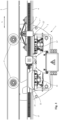
- Fig. 1 shows a side plan view of a section of a conductor rail system 1 according to the invention with a substantially double-U-shaped rail track 2.
- a current collector 3 of an electrical consumer (not shown) with rollers 4 can be moved in a longitudinal direction L.
- the current collector 3 serves to supply the electrical consumer that can be moved along the rail track 2, for example a container crane.
- a conductor rail 6 is attached hanging downwards by means of conductor rail holders 5 which are spaced apart from one another in the longitudinal direction L of the rail strand 2.
- the conductor rail 6 points in Fig. 2 clearly visible three conductor strand holders 7, 7 'and 7" arranged next to one another for holding elongated phase conductor strands 8, 8' and 8". Since the phase conductor strands 8' and 8" are designed identically to the phase conductor strand 8, the statements made regarding the phase conductor strand 8 apply accordingly.
- the phase conductor strand 8 has an elongated insulating profile 9, which is held by the conductor strand holder 7.
- the sliding contact carrier 13 with sliding contact 12 can be carried out in a manner known per se via an in Fig. 1 shown as an example, known delivery mechanism 14 can be moved towards the grinding surface 11 and away from it.
- the sliding contact 12 is constantly pressed against the grinding surface 11, for example via spring force.
- Fig. 2 The further sliding contacts 12' and 12" shown with associated sliding contact carriers are largely identical to the sliding contact 12 and sliding contact carrier 13, so that the statements made in this regard apply accordingly.
- each sliding contact 12, 12' or 12" has its own feed mechanism 14.
- phase conductor strand 8 serves to supply energy to the movable consumer and is live during normal operation, so that current flows via the grinding surface 11 to the sliding contact 12.
- a grounding conductor strand 15 is usually provided for connecting the movable electrical consumer to the ground potential of the conductor rail system 1.
- the grounding conductor strand 15 is described below primarily based on the detailed drawing Fig. 2a described.
- the grounding conductor strand 15 has an electrically conductive grounding conductor profile 16, which is surrounded by a substantially U-shaped grounding insulating profile 17 with an in Fig. 2a downwardly open contact opening 18 is surrounded.
- the grounding conductor strand 15 is attached to the conductor rail 6 with a conductor strand holder 7''' like the phase conductor strands 8, 8', 8".
- a right ground sliding contact 19 and a left ground sliding contact 20 as well as an antenna 21 arranged between them and electrically insulated from the ground sliding contacts 19, 20 are provided on the current collector 3, the antenna 21 representing a transmission unit.
- the antenna 21 and the ground sliding contacts 19, 20 can be raised via the delivery mechanism 14 and thereby brought and held in contact with corresponding ground sliding contact surfaces 22 and 23 of the ground conductor profile 16, as already described above.
- the grounding conductor profile 16 also forms a data transmission device with a hollow profile designed as a substantially T-shaped slot waveguide 24.
- the slot waveguide 24 has a cavity 25 which merges into a right or left slot wall 26, 27 of a longitudinal slot 28 which is open downwards in the drawings.
- the longitudinal slot 28 points in the same direction as the downwardly open contact opening 18.
- the antenna 21 which is aligned in the longitudinal direction L, can engage in the cavity 25 of the slot waveguide 24 in order to enable contactless data transmission, which is known per se.
- grounding conductor profile 16 and the slot waveguide 24 are made in one piece from the same material and thus form a structural unit, whereby production and installation can be simplified.
- grounding conductor profile 16 and slot waveguide 21 can also be made from separate parts and/or different materials.
- the slot waveguide 24 can also have another suitable cross section.
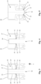
- Fig. 2a and in detail in Fig. 3 shown embodiment of the slot waveguide 24 at the inner, cavity-side end of the slot walls 26, 27 of the longitudinal slot 28, two sealing strips 29, 30 with circular thickened fastening edges 31, 32 in a right or left, correspondingly circular fastening groove 33, 34 attached. Thanks to these thickened fastening edges 31, 32, the sealing strips 29, 30 can be easily inserted into the fastening groove 33, 34 and still be held securely therein.
- the two fastening grooves 33, 34 are introduced into the slot waveguide 24 at an angle from the edge between the slot walls 26, 27 and the adjoining walls of the cavity 25.
- the sealing strips 29, 30 bend shortly after their thickened fastening edges 31, 32 so that they run parallel and in extension of the slot walls 26, 27 into the cavity 25 to an opposite upper wall 37 of the slot waveguide 24.
- the front, free ends of the sealing strips 29, 30 then come to rest in retaining grooves 35, 36 in the upper wall 37 in order to additionally stabilize their straight course and improve their sealing function.
- FIG. 4 The alternative embodiment shown of a data transmission device in the form of a slot waveguide 38 differs from that in Fig. 3 shown embodiment essentially through the alternative design of the sealing element.
- the same reference numbers and designations are therefore used for the same or corresponding parts; the above statements apply accordingly.
- slot waveguide 38 instead of the two separate sealing strips 29, 30 in the in Fig. 3 shown slot waveguide 38 only uses an elongated, continuous, trough-shaped sealing element 39.
- the sealing element 39 is attached with its thickened fastening edge 31 in the right fastening groove 33, as in the embodiment in Fig. 2a and 3 .
- the sealing element 39 then initially runs parallel and in extension of the right slot wall 26 into the cavity 25 to the opposite upper wall 37 of the slot waveguide 38, then turns at right angles in the direction of the other slot wall 27 and runs parallel to the upper wall 37.
- the sealing element 37 then bends again largely at right angles into the cavity 25, so that the sealing element 39 runs parallel and in an extension of the left slot wall 27 towards it.
- the sealing element 39 is then fastened again on this side with the thickened fastening edge 32 in the fastening groove 34 as described above.
- the sealing element 39 can advantageously protrude somewhat further into the cavity 25 than the antenna 21, so that the end face of the antenna 21 facing the upper wall 37 does not abut the sealing element 39.
- the trough-shaped sealing element 39 is preferably made of a dimensionally stable, to a certain extent elastic, non-electrically conductive material such as hard rubber, plastic or another plastic material.
- the distance between the sealing strips 29, 30 or the corresponding, opposing parts of the trough-shaped sealing element 39 can also narrow in the direction of the upper wall 37. This distance is preferably at least slightly larger than the width of the antenna 21 in order not to restrict its mobility when extending and extending as well as when moving along in the longitudinal direction L.
- FIG. 5 The alternative embodiment shown of a data transmission device in the form of a slot waveguide 38 differs from that in 3 and 4 shown embodiment essentially through the alternative design of the seal.
- the same reference numbers and designations are therefore used for the same or corresponding parts; the above statements apply accordingly.
- sealing lips 41, 42 arranged at the entrance of the longitudinal slot 28 are provided, which in turn are fastened to the slot waveguide 40 with thickened fastening edges 31, 32 in fastening grooves 43, 44.
- the sealing lips 41, 42 point obliquely away from the cavity 25 in the direction of the antenna 21 to be inserted and preferably lie against each other with their free ends in a sealing manner in the center line of the longitudinal slot 28. This can advantageously prevent the penetration of dirt and moisture at the entrance to the longitudinal slot 28, and the antenna 21 is also cleaned by the sealing lips 41, 42 when it penetrates into the longitudinal slot 28.
- the sealing strips 29, 30 or sealing lips 41, 42 are preferably made of a dimensionally stable, to a certain extent elastic, non-electrically conductive material such as hard rubber or another plastic material. If necessary, the sealing strips or sealing lips can also be made from a different material, e.g. B. made of a brush material, which on the one hand offers a sufficient sealing effect against dirt and moisture and on the other hand enables the antenna 21 to engage in the longitudinal slot 28 and does not hinder the movement of the antenna 21 in the longitudinal direction L too much. For example, so-called sealing brushes are known.
- a further antenna with lateral grounding contacts 22' can be arranged on a further delivery mechanism 14'.
- an interruption for example through a thermally separated connection point of the ground conductor profile 16 and slot waveguide 24, which is not made of endless material, can be bridged without interrupting the data transmission.
- the longitudinal slot 28 can advantageously also point in directions other than downwards, as shown in the drawings, since the sealing elements 29, 30, 39 or 41, 42 now prevent the penetration of moisture or dirt into the cavity 25.
- a transmission unit movable relative to the cavity is provided in an elongated hollow profile with a cavity running in a longitudinal direction of the hollow profile and a longitudinal slot running in the longitudinal direction is provided, which at least partially penetrates into the longitudinal slot.
Landscapes
- Engineering & Computer Science (AREA)
- Electromagnetism (AREA)
- Physics & Mathematics (AREA)
- Mechanical Engineering (AREA)
- General Health & Medical Sciences (AREA)
- Toxicology (AREA)
- Health & Medical Sciences (AREA)
- Power Engineering (AREA)
- Transportation (AREA)
- Near-Field Transmission Systems (AREA)
- Waveguide Aerials (AREA)
- Train Traffic Observation, Control, And Security (AREA)
- Communication Cables (AREA)
- Cable Transmission Systems, Equalization Of Radio And Reduction Of Echo (AREA)
Claims (10)
- Dispositif de transmission de données avec un profil creux (40) allongé avec un espace creux (25) s'étendant dans un sens longitudinal (L) du profil creux (40), dans lequel le profil creux (40) présente une entaille longitudinale (28) s'étendant dans le sens longitudinal (L) pour une unité de transmission (21) pouvant être déplacée par rapport à l'espace creux (25) au moins dans le sens longitudinal (L), pénétrant au moins en partie dans l'entaille longitudinale (28), dans lequel le profil creux (40) allongé est un conducteur creux à entaille (40) et l'unité de transmission est une antenne (21), dans lequel au moins un élément étanche (41, 42) s'étendant le long du profil creux (40) est prévu pour étanchéifier au moins une partie de l'espace creux (25), caractérisé en ce que respectivement un élément étanche (41, 42) est disposé sur le profil creux (40) sur des côtés se faisant face les uns les autres (26, 27) de l'entaille longitudinale (28), dans lequel les éléments étanches (41, 42) sont réalisés en tant que lèvres étanches, dans lequel pour empêcher la pénétration de saleté et d'humidité déjà à l'entrée de l'entaille longitudinale (28) et pour nettoyer l'antenne (21) lors de la pénétration dans l'entaille longitudinale (28) par les lèvres étanches (41, 42),- les lèvres étanches (41, 42) sont disposées sur l'entrée de l'entaille longitudinale (28) de telle sorte que l'entaille longitudinale (28) également est étanchéifiée par rapport à l'environnement extérieur,- les lèvres étanches (41, 42) présentent respectivement une arête de fixation (31, 32) épaissie par endroits dans la section transversale, destinée au maintien dans une rainure de fixation (33, 34) façonnée de manière correspondante du profil creux (24, 38 ; 40),- les lèvres étanches (41, 42) pointent à l'oblique de manière à s'éloigner de l'espace creux (25) en direction de l'antenne (21) à introduire, et dans lequel des extrémités libres, dépassant dans ou au-delà de l'entaille longitudinale (28), des éléments étanches (41, 42) se touchent de manière à étanchéifier de manière préférée dans la ligne médiane de l'entaille longitudinale (28).
- Dispositif de transmission de données avec un profil creux (38) allongé avec un espace creux (25) s'étendant dans un sens longitudinal (L) du profil creux (38), dans lequel le profil creux (38) présente une entaille longitudinale (28) s'étendant dans le sens longitudinal (L) pour une unité de transmission (21) pouvant être déplacée par rapport à l'espace creux (25) au moins dans le sens longitudinal (L), pénétrant au moins en partie dans l'entaille longitudinale (28), dans lequel un élément étanche (39) en forme d'auge, traversant, allongé s'étendant le long du profil creux (38) est prévu pour étanchéifier au moins une partie de l'espace creux (25), dans lequel l'élément étanche (39) est fixé sur les deux côtés de l'entaille longitudinale (28), dans lequel l'élément étanche (39) va au-delà de la largeur totale de l'entaille longitudinale (28), et dans lequel l'élément étanche (39) pointe dans l'espace creux (25), caractérisé en ce que l'élément étanche (39) s'étend à l'intérieur de l'espace creux (25) dans le prolongement de parois entaillées (26, 27) de l'entaille longitudinale (28).
- Dispositif de transmission de données avec un profil creux (24) allongé avec un espace creux (25) s'étendant dans un sens longitudinal (L) du profil creux (24), dans lequel le profil creux (24) présente une entaille longitudinale (28) s'étendant dans le sens longitudinal (L) pour une unité de transmission (21) pouvant être déplacée par rapport à l'espace creux (25) au moins dans le sens longitudinal (L), pénétrant au moins en partie dans l'entaille longitudinale (28), dans lequel deux éléments étanches (29, 30) s'étendant le long du profil creux (24) sont prévus pour étanchéifier au moins une partie de l'espace creux (25), caractérisé en ce que les éléments étanches (29, 30) sont disposés sur le passage entre l'espace creux (25) et l'entaille longitudinale (28), dans lequel les éléments étanches (29, 30) s'étendent à l'intérieur de l'espace creux (25) dans le prolongement de parois entaillées (26, 27) de l'entaille longitudinale (28), et dans lequel des rainures de maintien (35, 36) servant à loger des extrémités libres des éléments étanches (29, 30) sont prévues sur une paroi (37), faisant face à l'entaille longitudinale (28), de l'espace creux (25), et dans lequel les éléments étanches (29, 30) présentent respectivement une arête de fixation (31, 32) épaissie par endroits dans la section transversale pour le maintien dans une rainure de fixation (33, 34) façonnée de manière correspondante du profil creux (24, 28 ; 40).
- Dispositif de transmission de données selon la revendication 3, dans lequel respectivement un élément étanche (29, 30) est disposé sur le profil creux (24) sur des côtés (26, 27) se faisant face les uns les autres de l'entaille longitudinale (28).
- Dispositif de transmission de données selon l'une quelconque des revendications 3 ou 4, dans lequel les éléments étanches (29, 30) pointent dans l'espace creux (25).
- Dispositif de transmission de données selon la revendication 2, dans lequel l'élément étanche (39) est disposé sur le passage entre l'espace creux (25) et l'entaille longitudinale (28).
- Dispositif de transmission de données selon la revendication 1 ou 2, dans lequel l'élément étanche ou les éléments étanches (39 ; 41, 42) présentent respectivement une arête de fixation (31, 32) épaissie par endroits dans la section transversale pour le maintien dans une rainure de fixation (33, 34) façonnée de manière correspondante du profil creux (24, 38 ; 40).
- Dispositif de transmission de données selon la revendication 3 à 7, dans lequel l'arête de fixation (31, 32) épaissie est façonnée dans la section transversale de manière ronde circulaire, de manière ovale, en queue-d'aronde, en forme d'entonnoir ou en forme de coin.
- Ligne de contact (6) pour alimenter au moins un consommateur électrique pouvant être déplacé sur la ligne de contact (6) dans son sens longitudinal (L) en énergie électrique, avec au moins une corde conductrice (15) s'étendant dans le sens longitudinal (L) avec un profil conducteur (10, 16) électriquement conducteur pour établir un contact avec un contact glissant (22, 23) du consommateur et avec au moins un dispositif de transmission de données s'étendant dans le sens longitudinal (L), dans lequel le dispositif de transmission de données est réalisé selon l'une quelconque des revendications précédentes.
- Système de ligne de contact (1) avec une ligne de contact (6) selon la revendication 9, avec au moins un consommateur électrique pouvant être déplacé sur la ligne de contact (6) dans son sens longitudinal (L), qui présente un collecteur de courant (3) avec au moins un contact glissant (22, 23) pour établir un contact avec au moins un profil conducteur (10, 16) électriquement conducteur de la ligne de contact (6) et qui présente une unité de transmission (21) pour la transmission de données avec le dispositif de transmission de données de la ligne de contact (6).
Applications Claiming Priority (2)
| Application Number | Priority Date | Filing Date | Title |
|---|---|---|---|
| DE102016108442.5A DE102016108442A1 (de) | 2016-05-06 | 2016-05-06 | Datenübertragungsvorrichtung, Schleifleitung und Schleifleitungssystem |
| PCT/EP2017/055586 WO2017190877A1 (fr) | 2016-05-06 | 2017-03-09 | Dispositif de transmission de données, ligne de boucle et système de boucle |
Publications (3)
| Publication Number | Publication Date |
|---|---|
| EP3257100A1 EP3257100A1 (fr) | 2017-12-20 |
| EP3257100B1 EP3257100B1 (fr) | 2021-03-31 |
| EP3257100B2 true EP3257100B2 (fr) | 2024-02-14 |
Family
ID=58358558
Family Applications (1)
| Application Number | Title | Priority Date | Filing Date |
|---|---|---|---|
| EP17711591.2A Active EP3257100B2 (fr) | 2016-05-06 | 2017-03-09 | Dispositif de transmission de données, ligne de boucle et système de boucle |
Country Status (6)
| Country | Link |
|---|---|
| US (1) | US10822004B2 (fr) |
| EP (1) | EP3257100B2 (fr) |
| CN (1) | CN107851873B (fr) |
| DE (1) | DE102016108442A1 (fr) |
| FI (1) | FI3257100T4 (fr) |
| WO (1) | WO2017190877A1 (fr) |
Families Citing this family (5)
| Publication number | Priority date | Publication date | Assignee | Title |
|---|---|---|---|---|
| DE102016108442A1 (de) * | 2016-05-06 | 2017-11-09 | Conductix-Wampfler Gmbh | Datenübertragungsvorrichtung, Schleifleitung und Schleifleitungssystem |
| DE102018113849B4 (de) | 2018-06-11 | 2023-04-20 | Sick Ag | Optoelektronischer Sensor und Verfahren zu Erfassung von Objekten |
| DE102018127304B3 (de) * | 2018-10-31 | 2019-11-07 | Conductix-Wampfler Gmbh | Stromabnehmer, Schleifleitung und Schleifleitungssystem |
| EP3976440B1 (fr) * | 2019-05-29 | 2025-03-19 | Sew-Eurodrive GmbH & Co. KG | Système ferroviaire avec rail et pièces mobiles mobiles le long du rail |
| DE102023131552A1 (de) | 2023-11-13 | 2025-05-15 | Conductix-Wampfler Gmbh | Verbindungselement, Schleifleitung, Stromabnehmerwagen und Schleifleitungssystem |
Family Cites Families (38)
| Publication number | Priority date | Publication date | Assignee | Title |
|---|---|---|---|---|
| US448838A (en) * | 1891-03-24 | Thirds to elmer it | ||
| US540187A (en) * | 1895-05-28 | Closed-conduit system for electric railways | ||
| US434410A (en) * | 1890-08-12 | Closed conduit for electric conductors | ||
| US413294A (en) * | 1889-10-22 | Conduit for electric railways | ||
| US1010504A (en) * | 1911-03-20 | 1911-12-05 | Frederick Hale Lindsley | Third-rail covering. |
| US1048668A (en) * | 1911-08-04 | 1912-12-31 | Joseph E Evans | Sectional track. |
| US2151099A (en) * | 1938-12-07 | 1939-03-21 | Raybestos Manhattan Inc | Trolley wire guard |
| US3439131A (en) * | 1967-03-30 | 1969-04-15 | U S Electric Mfg Co | Trolley conductor guard |
| US4083439A (en) * | 1975-09-16 | 1978-04-11 | Chandler Leo E | Power collection device for electric powered rail cars |
| DE2555909C3 (de) * | 1975-12-12 | 1978-06-01 | Messerschmitt-Boelkow-Blohm Gmbh, 8000 Muenchen | Einrichtung zur Nachrichtenübertragung zwischen eine m mit einer Antenne versehenen spurgebundenen Fahrzeug und einem parallel zur Fahrspur angeordneten Hohlleiter |
| US4050555A (en) * | 1976-05-25 | 1977-09-27 | U-S Safety Trolley Corporation | Trolley rail assembly |
| DE2746718A1 (de) | 1977-10-18 | 1979-04-26 | Johann Proels Ing Fa | Vorrichtung zum staubdichten verschliessen eines gehaeuses |
| US4245727A (en) * | 1979-03-14 | 1981-01-20 | Pitcraft Summit Limited | Conduit |
| DE3215334C1 (de) * | 1982-04-24 | 1983-06-09 | Dr. Johannes Heidenhain Gmbh, 8225 Traunreut | Gekapselte Messeinrichtung |
| DE3323984A1 (de) | 1983-07-02 | 1985-01-03 | Messerschmitt-Bölkow-Blohm GmbH, 8012 Ottobrunn | Mit einem laengs einer fahrspur sich erstreckenden schlitzhohlleiter koppelbare antenne eines fahrzeugs |
| DE3719213C1 (de) * | 1987-06-09 | 1988-05-19 | Daimler Benz Ag | Bodennahe mehrpolige Stromversorgung fuer spurfuehrbare,gummibereifte,elektrisch antreibbare Fahrzeuge |
| DE58900833D1 (de) * | 1988-06-29 | 1992-03-26 | Heidenhain Gmbh Dr Johannes | Positionsmesseinrichtung. |
| US5258931A (en) * | 1988-07-08 | 1993-11-02 | Parker-Hannifin Corporation | Precision electronic absolute and relative position sensing device and method of using same |
| DE3903950A1 (de) | 1989-02-10 | 1990-08-16 | Wampfler Gmbh | Stromschiene sowie ein montageverfahren hierfuer |
| DE9104066U1 (de) | 1991-04-04 | 1991-06-27 | REHAU AG + Co, 8673 Rehau | Elastischer Verschluß |
| DE29616329U1 (de) | 1996-09-19 | 1996-11-14 | Steeger, Siegfried, 59174 Kamen | Schutzeinrichtung für mehrere stromführende Schienen aufweisende Schleifleitungen |
| DE10219452A1 (de) | 2002-04-30 | 2004-02-05 | Paul Vahle & Co. Kg | Schleifleitung mit einer Anzahl von Stromschienen, wobei eine Stromschiene als Halterung für eine Code-Schiene dient |
| DE102004008571B4 (de) | 2004-02-19 | 2012-09-06 | Paul Vahle Gmbh & Co. Kg | Tragschienenprofil mit integriertem Schlitzhohlleiter zur Datenübertragung |
| US7596880B2 (en) * | 2005-09-13 | 2009-10-06 | Dr. Johannes Heidenhain Gmbh | Scanning unit of an optical position measuring device and optical position measuring device |
| DE102005043433A1 (de) | 2005-09-13 | 2007-03-15 | Dr. Johannes Heidenhain Gmbh | Abtasteinheit einer optischen Positionsmesseinrichtung und optische Positionsmesseinrichtung |
| DE102008045482C5 (de) * | 2008-09-03 | 2024-10-02 | Conductix-Wampfler Gmbh | Schleifleitung, Stromabnehmer und Schleifleitungssystem |
| DE102009004782B4 (de) * | 2009-01-13 | 2020-10-22 | Sew-Eurodrive Gmbh & Co Kg | Vorrichtung zur berührungslosen Energieübertragung |
| DE102011119351B4 (de) | 2011-03-31 | 2015-07-30 | Sew-Eurodrive Gmbh & Co Kg | Transportsystem |
| DE102012002085A1 (de) | 2012-02-06 | 2013-08-08 | Sew-Eurodrive Gmbh & Co. Kg | Schlitzhohlleiter für elektromagnetische Wellen und Anlage |
| DE102012203220A1 (de) * | 2012-03-01 | 2013-09-05 | Dr. Johannes Heidenhain Gmbh | Längenmesseinrichtung |
| DE102012203193A1 (de) * | 2012-03-01 | 2013-09-05 | Dr. Johannes Heidenhain Gmbh | Längenmesseinrichtung |
| DE102014102490A1 (de) * | 2014-02-26 | 2015-08-27 | Miele & Cie. Kg | Heißgetränkeautomat mit Objekterkennungsmittel |
| DE202014011153U1 (de) * | 2014-03-19 | 2018-03-05 | Paul Vahle Gmbh & Co. Kg | Schlitzhohlleiter |
| DE102014107468A1 (de) * | 2014-05-27 | 2015-12-03 | Conductix-Wampfler Gmbh | Schleifleitung, Stromabnehmer und Schleifleitungssystem |
| DE102014107466B4 (de) | 2014-05-27 | 2016-01-07 | Conductix-Wampfler Gmbh | Schleifleitung, Stromabnehmer und Schleifleitungssystem |
| DE202014102490U1 (de) * | 2014-05-27 | 2015-09-11 | Conductix-Wampfler Gmbh | Schleifleitung, Stromabnehmer und Schleifleitungssystem |
| DE102016108442A1 (de) * | 2016-05-06 | 2017-11-09 | Conductix-Wampfler Gmbh | Datenübertragungsvorrichtung, Schleifleitung und Schleifleitungssystem |
| DE102016116396A1 (de) * | 2016-09-01 | 2018-03-15 | Conductix-Wampfler Gmbh | Schleifleitung, Stromabnehmer, Schleifleitungssystem und Verfahren zur berührungslosen Datenübertragung |
-
2016
- 2016-05-06 DE DE102016108442.5A patent/DE102016108442A1/de not_active Withdrawn
-
2017
- 2017-03-09 US US15/552,934 patent/US10822004B2/en active Active
- 2017-03-09 WO PCT/EP2017/055586 patent/WO2017190877A1/fr not_active Ceased
- 2017-03-09 CN CN201780000989.8A patent/CN107851873B/zh active Active
- 2017-03-09 FI FIEP17711591.2T patent/FI3257100T4/fi active
- 2017-03-09 EP EP17711591.2A patent/EP3257100B2/fr active Active
Also Published As
| Publication number | Publication date |
|---|---|
| US10822004B2 (en) | 2020-11-03 |
| EP3257100B1 (fr) | 2021-03-31 |
| EP3257100A1 (fr) | 2017-12-20 |
| US20180170411A1 (en) | 2018-06-21 |
| HK1247444A1 (zh) | 2018-09-21 |
| CN107851873A (zh) | 2018-03-27 |
| DE102016108442A1 (de) | 2017-11-09 |
| WO2017190877A1 (fr) | 2017-11-09 |
| FI3257100T4 (fi) | 2024-05-16 |
| CN107851873B (zh) | 2021-06-01 |
Similar Documents
| Publication | Publication Date | Title |
|---|---|---|
| EP3257100B2 (fr) | Dispositif de transmission de données, ligne de boucle et système de boucle | |
| EP2969637B1 (fr) | Ligne de contact, balai conducteur et système de ligne de contact équipé d'un guide d'ondes à fente destiné à recevoir une antenne | |
| EP2964481B1 (fr) | Ligne à frottement, collecteur de courant et système à ligne à frottement | |
| DE202016102435U1 (de) | Datenübertragungsvorrichtung, Schleifleitung und Schleifleitungssystem | |
| DE102008045482C5 (de) | Schleifleitung, Stromabnehmer und Schleifleitungssystem | |
| EP2862244B1 (fr) | Élément d'assemblage pour ligne de contact, ligne de contact et procédé de fabrication d'une ligne de contact | |
| DE69601505T2 (de) | Stromversorgungseinrichtung und einrichtung zum führen einer schiene entlang am boden für ein radfahrzeug | |
| EP2683570B1 (fr) | Attache pour un conducteur de données, système de transmission d'énergie et système de transmission de données | |
| DE19839258A1 (de) | Elektrische Verbindung | |
| DE102015101849A1 (de) | Stromabnehmer und Schleifleitungssystem | |
| DE102015101848B4 (de) | Stromabnehmer und Schleifleitungssystem | |
| EP3271208B1 (fr) | Dispositif de transmission de données et dispositif de transmission d'énergie électrique par conduction | |
| EP2931553B1 (fr) | Rail d'alimentation | |
| CH697948B1 (de) | Stromschiene. | |
| DE202014102490U1 (de) | Schleifleitung, Stromabnehmer und Schleifleitungssystem | |
| EP3507127B1 (fr) | Ligne à contact glissant, collecteur de courant, système de ligne à contact glissant et procédé de transmission de données sans contact | |
| EP4265465A1 (fr) | Support de contact à frottement, contact à frottement, collecteur de courant et système de ligne à frottement | |
| DE873396C (de) | Gegen unabsichtliche Beruehrung geschuetzte elektrische Schleifleitung mit darin gefuehrten Stromabnehmern | |
| DE202016104836U1 (de) | Schleifleitung, Stromabnehmer und Schleifleitungssystem | |
| DE102018127304B3 (de) | Stromabnehmer, Schleifleitung und Schleifleitungssystem | |
| DE202015100622U1 (de) | Stromabnehmer und Schleifleitungssystem | |
| DE102018131568A1 (de) | Stromführungsprofil | |
| DE4308735C1 (de) | Vorrichtung zur digitalen Datenübertragung | |
| DE202014102489U1 (de) | Schleifleitung, Stromabnehmer und Schleifleitungssystem | |
| DE202016101174U1 (de) | Datenübertragungsvorrichtung und Vorrichtung zum konduktiven Übertragen elektrischer Energie |
Legal Events
| Date | Code | Title | Description |
|---|---|---|---|
| STAA | Information on the status of an ep patent application or granted ep patent |
Free format text: STATUS: UNKNOWN |
|
| STAA | Information on the status of an ep patent application or granted ep patent |
Free format text: STATUS: THE INTERNATIONAL PUBLICATION HAS BEEN MADE |
|
| PUAI | Public reference made under article 153(3) epc to a published international application that has entered the european phase |
Free format text: ORIGINAL CODE: 0009012 |
|
| STAA | Information on the status of an ep patent application or granted ep patent |
Free format text: STATUS: REQUEST FOR EXAMINATION WAS MADE |
|
| 17P | Request for examination filed |
Effective date: 20170718 |
|
| AK | Designated contracting states |
Kind code of ref document: A1 Designated state(s): AL AT BE BG CH CY CZ DE DK EE ES FI FR GB GR HR HU IE IS IT LI LT LU LV MC MK MT NL NO PL PT RO RS SE SI SK SM TR |
|
| AX | Request for extension of the european patent |
Extension state: BA ME |
|
| DAV | Request for validation of the european patent (deleted) | ||
| DAX | Request for extension of the european patent (deleted) | ||
| STAA | Information on the status of an ep patent application or granted ep patent |
Free format text: STATUS: EXAMINATION IS IN PROGRESS |
|
| 17Q | First examination report despatched |
Effective date: 20200318 |
|
| RIC1 | Information provided on ipc code assigned before grant |
Ipc: B61L 3/22 20060101ALI20201030BHEP Ipc: H01P 3/123 20060101AFI20201030BHEP Ipc: H01Q 1/42 20060101ALN20201030BHEP Ipc: H01Q 1/32 20060101ALI20201030BHEP |
|
| GRAP | Despatch of communication of intention to grant a patent |
Free format text: ORIGINAL CODE: EPIDOSNIGR1 |
|
| STAA | Information on the status of an ep patent application or granted ep patent |
Free format text: STATUS: GRANT OF PATENT IS INTENDED |
|
| INTG | Intention to grant announced |
Effective date: 20201214 |
|
| GRAS | Grant fee paid |
Free format text: ORIGINAL CODE: EPIDOSNIGR3 |
|
| GRAA | (expected) grant |
Free format text: ORIGINAL CODE: 0009210 |
|
| STAA | Information on the status of an ep patent application or granted ep patent |
Free format text: STATUS: THE PATENT HAS BEEN GRANTED |
|
| AK | Designated contracting states |
Kind code of ref document: B1 Designated state(s): AL AT BE BG CH CY CZ DE DK EE ES FI FR GB GR HR HU IE IS IT LI LT LU LV MC MK MT NL NO PL PT RO RS SE SI SK SM TR |
|
| REG | Reference to a national code |
Ref country code: GB Ref legal event code: FG4D Free format text: NOT ENGLISH Ref country code: CH Ref legal event code: EP |
|
| REG | Reference to a national code |
Ref country code: AT Ref legal event code: REF Ref document number: 1377970 Country of ref document: AT Kind code of ref document: T Effective date: 20210415 |
|
| REG | Reference to a national code |
Ref country code: DE Ref legal event code: R096 Ref document number: 502017009885 Country of ref document: DE |
|
| REG | Reference to a national code |
Ref country code: IE Ref legal event code: FG4D Free format text: LANGUAGE OF EP DOCUMENT: GERMAN |
|
| REG | Reference to a national code |
Ref country code: FI Ref legal event code: FGE |
|
| REG | Reference to a national code |
Ref country code: LT Ref legal event code: MG9D |
|
| PG25 | Lapsed in a contracting state [announced via postgrant information from national office to epo] |
Ref country code: NO Free format text: LAPSE BECAUSE OF FAILURE TO SUBMIT A TRANSLATION OF THE DESCRIPTION OR TO PAY THE FEE WITHIN THE PRESCRIBED TIME-LIMIT Effective date: 20210630 Ref country code: HR Free format text: LAPSE BECAUSE OF FAILURE TO SUBMIT A TRANSLATION OF THE DESCRIPTION OR TO PAY THE FEE WITHIN THE PRESCRIBED TIME-LIMIT Effective date: 20210331 Ref country code: BG Free format text: LAPSE BECAUSE OF FAILURE TO SUBMIT A TRANSLATION OF THE DESCRIPTION OR TO PAY THE FEE WITHIN THE PRESCRIBED TIME-LIMIT Effective date: 20210630 |
|
| PG25 | Lapsed in a contracting state [announced via postgrant information from national office to epo] |
Ref country code: RS Free format text: LAPSE BECAUSE OF FAILURE TO SUBMIT A TRANSLATION OF THE DESCRIPTION OR TO PAY THE FEE WITHIN THE PRESCRIBED TIME-LIMIT Effective date: 20210331 Ref country code: LV Free format text: LAPSE BECAUSE OF FAILURE TO SUBMIT A TRANSLATION OF THE DESCRIPTION OR TO PAY THE FEE WITHIN THE PRESCRIBED TIME-LIMIT Effective date: 20210331 Ref country code: SE Free format text: LAPSE BECAUSE OF FAILURE TO SUBMIT A TRANSLATION OF THE DESCRIPTION OR TO PAY THE FEE WITHIN THE PRESCRIBED TIME-LIMIT Effective date: 20210331 |
|
| REG | Reference to a national code |
Ref country code: NL Ref legal event code: MP Effective date: 20210331 |
|
| PG25 | Lapsed in a contracting state [announced via postgrant information from national office to epo] |
Ref country code: CZ Free format text: LAPSE BECAUSE OF FAILURE TO SUBMIT A TRANSLATION OF THE DESCRIPTION OR TO PAY THE FEE WITHIN THE PRESCRIBED TIME-LIMIT Effective date: 20210331 Ref country code: EE Free format text: LAPSE BECAUSE OF FAILURE TO SUBMIT A TRANSLATION OF THE DESCRIPTION OR TO PAY THE FEE WITHIN THE PRESCRIBED TIME-LIMIT Effective date: 20210331 Ref country code: LT Free format text: LAPSE BECAUSE OF FAILURE TO SUBMIT A TRANSLATION OF THE DESCRIPTION OR TO PAY THE FEE WITHIN THE PRESCRIBED TIME-LIMIT Effective date: 20210331 Ref country code: NL Free format text: LAPSE BECAUSE OF FAILURE TO SUBMIT A TRANSLATION OF THE DESCRIPTION OR TO PAY THE FEE WITHIN THE PRESCRIBED TIME-LIMIT Effective date: 20210331 Ref country code: SM Free format text: LAPSE BECAUSE OF FAILURE TO SUBMIT A TRANSLATION OF THE DESCRIPTION OR TO PAY THE FEE WITHIN THE PRESCRIBED TIME-LIMIT Effective date: 20210331 |
|
| PG25 | Lapsed in a contracting state [announced via postgrant information from national office to epo] |
Ref country code: PL Free format text: LAPSE BECAUSE OF FAILURE TO SUBMIT A TRANSLATION OF THE DESCRIPTION OR TO PAY THE FEE WITHIN THE PRESCRIBED TIME-LIMIT Effective date: 20210331 Ref country code: PT Free format text: LAPSE BECAUSE OF FAILURE TO SUBMIT A TRANSLATION OF THE DESCRIPTION OR TO PAY THE FEE WITHIN THE PRESCRIBED TIME-LIMIT Effective date: 20210802 Ref country code: SK Free format text: LAPSE BECAUSE OF FAILURE TO SUBMIT A TRANSLATION OF THE DESCRIPTION OR TO PAY THE FEE WITHIN THE PRESCRIBED TIME-LIMIT Effective date: 20210331 Ref country code: RO Free format text: LAPSE BECAUSE OF FAILURE TO SUBMIT A TRANSLATION OF THE DESCRIPTION OR TO PAY THE FEE WITHIN THE PRESCRIBED TIME-LIMIT Effective date: 20210331 Ref country code: IS Free format text: LAPSE BECAUSE OF FAILURE TO SUBMIT A TRANSLATION OF THE DESCRIPTION OR TO PAY THE FEE WITHIN THE PRESCRIBED TIME-LIMIT Effective date: 20210731 |
|
| REG | Reference to a national code |
Ref country code: DE Ref legal event code: R026 Ref document number: 502017009885 Country of ref document: DE |
|
| PLBI | Opposition filed |
Free format text: ORIGINAL CODE: 0009260 |
|
| REG | Reference to a national code |
Ref country code: FI Ref legal event code: MDE Opponent name: SEW-EURODRIVE GMBH & CO. KG |
|
| 26 | Opposition filed |
Opponent name: SEW-EURODRIVE GMBH & CO. KG Effective date: 20211130 |
|
| PLAX | Notice of opposition and request to file observation + time limit sent |
Free format text: ORIGINAL CODE: EPIDOSNOBS2 |
|
| PG25 | Lapsed in a contracting state [announced via postgrant information from national office to epo] |
Ref country code: ES Free format text: LAPSE BECAUSE OF FAILURE TO SUBMIT A TRANSLATION OF THE DESCRIPTION OR TO PAY THE FEE WITHIN THE PRESCRIBED TIME-LIMIT Effective date: 20210331 Ref country code: DK Free format text: LAPSE BECAUSE OF FAILURE TO SUBMIT A TRANSLATION OF THE DESCRIPTION OR TO PAY THE FEE WITHIN THE PRESCRIBED TIME-LIMIT Effective date: 20210331 Ref country code: AL Free format text: LAPSE BECAUSE OF FAILURE TO SUBMIT A TRANSLATION OF THE DESCRIPTION OR TO PAY THE FEE WITHIN THE PRESCRIBED TIME-LIMIT Effective date: 20210331 |
|
| PLBB | Reply of patent proprietor to notice(s) of opposition received |
Free format text: ORIGINAL CODE: EPIDOSNOBS3 |
|
| PG25 | Lapsed in a contracting state [announced via postgrant information from national office to epo] |
Ref country code: IS Free format text: LAPSE BECAUSE OF FAILURE TO SUBMIT A TRANSLATION OF THE DESCRIPTION OR TO PAY THE FEE WITHIN THE PRESCRIBED TIME-LIMIT Effective date: 20210731 |
|
| PG25 | Lapsed in a contracting state [announced via postgrant information from national office to epo] |
Ref country code: IT Free format text: LAPSE BECAUSE OF FAILURE TO SUBMIT A TRANSLATION OF THE DESCRIPTION OR TO PAY THE FEE WITHIN THE PRESCRIBED TIME-LIMIT Effective date: 20210331 |
|
| PG25 | Lapsed in a contracting state [announced via postgrant information from national office to epo] |
Ref country code: MC Free format text: LAPSE BECAUSE OF FAILURE TO SUBMIT A TRANSLATION OF THE DESCRIPTION OR TO PAY THE FEE WITHIN THE PRESCRIBED TIME-LIMIT Effective date: 20210331 |
|
| REG | Reference to a national code |
Ref country code: CH Ref legal event code: PL |
|
| GBPC | Gb: european patent ceased through non-payment of renewal fee |
Effective date: 20220309 |
|
| REG | Reference to a national code |
Ref country code: BE Ref legal event code: MM Effective date: 20220331 |
|
| PG25 | Lapsed in a contracting state [announced via postgrant information from national office to epo] |
Ref country code: LU Free format text: LAPSE BECAUSE OF NON-PAYMENT OF DUE FEES Effective date: 20220309 Ref country code: LI Free format text: LAPSE BECAUSE OF NON-PAYMENT OF DUE FEES Effective date: 20220331 Ref country code: IE Free format text: LAPSE BECAUSE OF NON-PAYMENT OF DUE FEES Effective date: 20220309 Ref country code: GB Free format text: LAPSE BECAUSE OF NON-PAYMENT OF DUE FEES Effective date: 20220309 Ref country code: FR Free format text: LAPSE BECAUSE OF NON-PAYMENT OF DUE FEES Effective date: 20220331 Ref country code: CH Free format text: LAPSE BECAUSE OF NON-PAYMENT OF DUE FEES Effective date: 20220331 |
|
| PG25 | Lapsed in a contracting state [announced via postgrant information from national office to epo] |
Ref country code: BE Free format text: LAPSE BECAUSE OF NON-PAYMENT OF DUE FEES Effective date: 20220331 |
|
| REG | Reference to a national code |
Ref country code: AT Ref legal event code: MM01 Ref document number: 1377970 Country of ref document: AT Kind code of ref document: T Effective date: 20220309 |
|
| P01 | Opt-out of the competence of the unified patent court (upc) registered |
Effective date: 20230508 |
|
| PG25 | Lapsed in a contracting state [announced via postgrant information from national office to epo] |
Ref country code: AT Free format text: LAPSE BECAUSE OF NON-PAYMENT OF DUE FEES Effective date: 20220309 |
|
| APBM | Appeal reference recorded |
Free format text: ORIGINAL CODE: EPIDOSNREFNO |
|
| APBP | Date of receipt of notice of appeal recorded |
Free format text: ORIGINAL CODE: EPIDOSNNOA2O |
|
| APAH | Appeal reference modified |
Free format text: ORIGINAL CODE: EPIDOSCREFNO |
|
| APBU | Appeal procedure closed |
Free format text: ORIGINAL CODE: EPIDOSNNOA9O |
|
| PUAH | Patent maintained in amended form |
Free format text: ORIGINAL CODE: 0009272 |
|
| STAA | Information on the status of an ep patent application or granted ep patent |
Free format text: STATUS: PATENT MAINTAINED AS AMENDED |
|
| 27A | Patent maintained in amended form |
Effective date: 20240214 |
|
| AK | Designated contracting states |
Kind code of ref document: B2 Designated state(s): AL AT BE BG CH CY CZ DE DK EE ES FI FR GB GR HR HU IE IS IT LI LT LU LV MC MK MT NL NO PL PT RO RS SE SI SK SM TR |
|
| REG | Reference to a national code |
Ref country code: DE Ref legal event code: R102 Ref document number: 502017009885 Country of ref document: DE |
|
| PG25 | Lapsed in a contracting state [announced via postgrant information from national office to epo] |
Ref country code: HU Free format text: LAPSE BECAUSE OF FAILURE TO SUBMIT A TRANSLATION OF THE DESCRIPTION OR TO PAY THE FEE WITHIN THE PRESCRIBED TIME-LIMIT; INVALID AB INITIO Effective date: 20170309 |
|
| PG25 | Lapsed in a contracting state [announced via postgrant information from national office to epo] |
Ref country code: MK Free format text: LAPSE BECAUSE OF FAILURE TO SUBMIT A TRANSLATION OF THE DESCRIPTION OR TO PAY THE FEE WITHIN THE PRESCRIBED TIME-LIMIT Effective date: 20210331 Ref country code: CY Free format text: LAPSE BECAUSE OF FAILURE TO SUBMIT A TRANSLATION OF THE DESCRIPTION OR TO PAY THE FEE WITHIN THE PRESCRIBED TIME-LIMIT Effective date: 20210331 |
|
| PG25 | Lapsed in a contracting state [announced via postgrant information from national office to epo] |
Ref country code: MT Free format text: LAPSE BECAUSE OF FAILURE TO SUBMIT A TRANSLATION OF THE DESCRIPTION OR TO PAY THE FEE WITHIN THE PRESCRIBED TIME-LIMIT Effective date: 20210331 |
|
| PG25 | Lapsed in a contracting state [announced via postgrant information from national office to epo] |
Ref country code: GR Free format text: LAPSE BECAUSE OF NON-PAYMENT OF DUE FEES Effective date: 20210331 |
|
| PG25 | Lapsed in a contracting state [announced via postgrant information from national office to epo] |
Ref country code: GR Free format text: LAPSE BECAUSE OF NON-PAYMENT OF DUE FEES Effective date: 20210331 |
|
| PGFP | Annual fee paid to national office [announced via postgrant information from national office to epo] |
Ref country code: TR Payment date: 20250226 Year of fee payment: 9 |
|
| PGFP | Annual fee paid to national office [announced via postgrant information from national office to epo] |
Ref country code: DE Payment date: 20250415 Year of fee payment: 9 |
|
| PGFP | Annual fee paid to national office [announced via postgrant information from national office to epo] |
Ref country code: FI Payment date: 20260320 Year of fee payment: 10 |