EP3257712B1 - Systeme und verfahren zur detektion einer schleifenden bremse - Google Patents
Systeme und verfahren zur detektion einer schleifenden bremse Download PDFInfo
- Publication number
- EP3257712B1 EP3257712B1 EP17175809.7A EP17175809A EP3257712B1 EP 3257712 B1 EP3257712 B1 EP 3257712B1 EP 17175809 A EP17175809 A EP 17175809A EP 3257712 B1 EP3257712 B1 EP 3257712B1
- Authority
- EP
- European Patent Office
- Prior art keywords
- wheel
- controller
- speed characteristic
- average
- wheel speed
- Prior art date
- Legal status (The legal status is an assumption and is not a legal conclusion. Google has not performed a legal analysis and makes no representation as to the accuracy of the status listed.)
- Active
Links
Images




Classifications
-
- B—PERFORMING OPERATIONS; TRANSPORTING
- B64—AIRCRAFT; AVIATION; COSMONAUTICS
- B64F—GROUND OR AIRCRAFT-CARRIER-DECK INSTALLATIONS SPECIALLY ADAPTED FOR USE IN CONNECTION WITH AIRCRAFT; DESIGNING, MANUFACTURING, ASSEMBLING, CLEANING, MAINTAINING OR REPAIRING AIRCRAFT, NOT OTHERWISE PROVIDED FOR; HANDLING, TRANSPORTING, TESTING OR INSPECTING AIRCRAFT COMPONENTS, NOT OTHERWISE PROVIDED FOR
- B64F5/00—Designing, manufacturing, assembling, cleaning, maintaining or repairing aircraft, not otherwise provided for; Handling, transporting, testing or inspecting aircraft components, not otherwise provided for
- B64F5/60—Testing or inspecting aircraft components or systems
-
- B—PERFORMING OPERATIONS; TRANSPORTING
- B60—VEHICLES IN GENERAL
- B60T—VEHICLE BRAKE CONTROL SYSTEMS OR PARTS THEREOF; BRAKE CONTROL SYSTEMS OR PARTS THEREOF, IN GENERAL; ARRANGEMENT OF BRAKING ELEMENTS ON VEHICLES IN GENERAL; PORTABLE DEVICES FOR PREVENTING UNWANTED MOVEMENT OF VEHICLES; VEHICLE MODIFICATIONS TO FACILITATE COOLING OF BRAKES
- B60T8/00—Arrangements for adjusting wheel-braking force to meet varying vehicular or ground-surface conditions, e.g. limiting or varying distribution of braking force
- B60T8/17—Using electrical or electronic regulation means to control braking
- B60T8/1701—Braking or traction control means specially adapted for particular types of vehicles
- B60T8/1703—Braking or traction control means specially adapted for particular types of vehicles for aircrafts
-
- B—PERFORMING OPERATIONS; TRANSPORTING
- B60—VEHICLES IN GENERAL
- B60T—VEHICLE BRAKE CONTROL SYSTEMS OR PARTS THEREOF; BRAKE CONTROL SYSTEMS OR PARTS THEREOF, IN GENERAL; ARRANGEMENT OF BRAKING ELEMENTS ON VEHICLES IN GENERAL; PORTABLE DEVICES FOR PREVENTING UNWANTED MOVEMENT OF VEHICLES; VEHICLE MODIFICATIONS TO FACILITATE COOLING OF BRAKES
- B60T17/00—Component parts, details, or accessories of power brake systems not covered by groups B60T8/00, B60T13/00 or B60T15/00, or presenting other characteristic features
- B60T17/18—Safety devices; Monitoring
- B60T17/22—Devices for monitoring or checking brake systems; Signal devices
- B60T17/221—Procedure or apparatus for checking or keeping in a correct functioning condition of brake systems
-
- B—PERFORMING OPERATIONS; TRANSPORTING
- B64—AIRCRAFT; AVIATION; COSMONAUTICS
- B64C—AEROPLANES; HELICOPTERS
- B64C25/00—Alighting gear
- B64C25/32—Alighting gear characterised by elements which contact the ground or similar surface
- B64C25/34—Alighting gear characterised by elements which contact the ground or similar surface wheeled type, e.g. multi-wheeled bogies
-
- B—PERFORMING OPERATIONS; TRANSPORTING
- B64—AIRCRAFT; AVIATION; COSMONAUTICS
- B64C—AEROPLANES; HELICOPTERS
- B64C25/00—Alighting gear
- B64C25/32—Alighting gear characterised by elements which contact the ground or similar surface
- B64C25/42—Arrangement or adaptation of brakes
-
- B—PERFORMING OPERATIONS; TRANSPORTING
- B64—AIRCRAFT; AVIATION; COSMONAUTICS
- B64D—EQUIPMENT FOR FITTING IN OR TO AIRCRAFT; FLIGHT SUITS; PARACHUTES; ARRANGEMENT OR MOUNTING OF POWER PLANTS OR PROPULSION TRANSMISSIONS IN AIRCRAFT
- B64D45/00—Aircraft indicators or protectors not otherwise provided for
-
- B—PERFORMING OPERATIONS; TRANSPORTING
- B60—VEHICLES IN GENERAL
- B60T—VEHICLE BRAKE CONTROL SYSTEMS OR PARTS THEREOF; BRAKE CONTROL SYSTEMS OR PARTS THEREOF, IN GENERAL; ARRANGEMENT OF BRAKING ELEMENTS ON VEHICLES IN GENERAL; PORTABLE DEVICES FOR PREVENTING UNWANTED MOVEMENT OF VEHICLES; VEHICLE MODIFICATIONS TO FACILITATE COOLING OF BRAKES
- B60T2270/00—Further aspects of brake control systems not otherwise provided for
- B60T2270/40—Failsafe aspects of brake control systems
- B60T2270/406—Test-mode; Self-diagnosis
-
- B—PERFORMING OPERATIONS; TRANSPORTING
- B64—AIRCRAFT; AVIATION; COSMONAUTICS
- B64D—EQUIPMENT FOR FITTING IN OR TO AIRCRAFT; FLIGHT SUITS; PARACHUTES; ARRANGEMENT OR MOUNTING OF POWER PLANTS OR PROPULSION TRANSMISSIONS IN AIRCRAFT
- B64D45/00—Aircraft indicators or protectors not otherwise provided for
- B64D2045/0085—Devices for aircraft health monitoring, e.g. monitoring flutter or vibration
Definitions
- the present invention relates to aircraft systems, and, more specifically, to aircraft landing gear systems.
- Aircraft often include one or more landing gear that comprise one or more wheels. Each wheel may have a brake that is operatively coupled to the wheel to slow the wheel, and hence the aircraft, during, for example, landing or a rejected takeoff. Aircraft brakes are not typically engaged voluntarily during takeoff, as brake engagement would act to impede forward motion of the aircraft. However, in the event of brake malfunction, one or more brakes may be at least partially engaged during a takeoff. Such engagement may not be enough to affect the ability of the aircraft to takeoff, and indeed, may be undetectable to the aircraft pilot and crew. In other cases, a dragging brake may prevent an aircraft from achieving takeoff speed. A pilot may elect to reject the takeoff in response to a dragging brake. A concern is that partial engagement of an aircraft brake during takeoff tends to generate heat in the brake, as the brake absorbs energy from the rotation of the wheel and thus increases in temperature. Partial engagement of an aircraft brake during takeoff may also prevent the aircraft from reaching an appropriate takeoff speed.
- landing gear may be stowed by retracting the landing gear into a wheel well of an airframe.
- the wheel may or may not be rotating.
- the braking system may be commanded to apply braking pressure to the wheels in order to slow or stop the wheel rotation before, during, and/or after retraction into the aircraft body.
- a brake that is at least partially engaged at a time when no braking is commanded may be referred to as a "dragging" brake. If a brake drags during takeoff, it is not desirable to retract the wheel into the wheel well after takeoff due to the excess temperature of the brake. Retraction of a hot brake may pose a fire hazard and/or cause the tire to become too hot and fail.
- GB 2468378A describes a system and method for detecting a dragging brake.
- a landing gear assembly is defined in claim 1 and includes a first wheel and a second wheel, a first wheel sensor coupled to the first wheel and a second wheel sensor coupled to the second wheel, and a controller coupled to the first wheel sensor and the second wheel sensor.
- a tangible, non-transitory memory has instructions for detecting a dragging brake.
- the controller performs operations including receiving data from the first wheel sensor and the second wheel sensor, calculating a wheel speed characteristic for each of the first wheel and the second wheel based on the data, identifying a lowest value for the wheel speed characteristic, determining a moving average for the wheel speed characteristic, comparing the lowest value to the moving average, and whether the lowest value for the wheel speed characteristic indicates a dragging brake.
- the operations further comprise generating, by the controller, a signal based on the dragging brake being present.
- the operations may further include determining, by the controller, an average wheel speed characteristic for a present takeoff, wherein the lowest value is excluded from the average, and storing, by the controller, the average wheel speed characteristic for the present takeoff, wherein the moving average is based on the average wheel speed characteristic for the present takeoff and is based on a stored average wheel speed characteristic from a past takeoff.
- the operations may further include evaluating, by the controller, the lowest value and the moving average against a threshold, wherein the threshold is based on the moving average.
- the threshold may be 50% to 70% of the moving average.
- the data may include a displacement, velocity, or acceleration, and the wheel speed characteristic may be a summation of the data during a time interval. The time interval may begin after takeoff and may end prior to a gear retract braking.
- the operations may further include generating, by the controller, a signal based on the dragging brake being present.
- An article of manufacture includes a non-transitory, tangible computer readable storage medium having instructions stored thereon that, in response to execution by a controller, cause the controller to perform operations.
- the operations include calculating, by the controller, a wheel speed characteristic for a first wheel and a second wheel.
- the operations include identifying, by the controller, a lowest value for the characteristic.
- the operations include determining, by the controller, a moving average for the characteristic.
- the operations include comparing, by the controller, the lowest value to the moving average.
- the operations include determining, by the controller, whether the lowest value for the wheel speed characteristic indicates a dragging brake, and receiving, by the controller, data from a first wheel sensor coupled to a first wheel of a landing gear and a second wheel sensor coupled to a second wheel of the landing gear.
- the operations may further include determining, by the controller, an average wheel speed characteristic for a present takeoff, wherein the lowest value is excluded from the average, and storing, by the controller, the average wheel speed characteristic for the present takeoff, wherein the moving average is based on the average wheel speed characteristic for the present takeoff and is based on a stored average wheel speed characteristic from a past takeoff.
- the operations may further include evaluating, by the controller, the lowest value and the moving average against a threshold, wherein the threshold is based on the moving average.
- the threshold may be 50% to 70% of the moving average.
- the wheel speed characteristic may be a summation of an angular velocity during a time interval. The time interval may begin after takeoff and may end prior to a gear retract braking.
- a method for detecting a dragging brake comprises the steps of receiving, by the controller, data from a first wheel sensor and a second wheel sensor, calculating, by the controller, a wheel speed characteristic for each of a first wheel and a second wheel based on the data, identifying, by the controller, a lowest value for the wheel speed characteristic, determining, by the controller, a moving average for the wheel speed characteristic, comparing, by the controller, the lowest value to the moving average, and determining, by the controller, whether the lowest value for the wheel speed characteristic indicates a dragging brake.
- the operations further comprise generating, by the controller, a signal based on the dragging break being present.
- the method may further include determining, by the controller, an average wheel speed characteristic for a present takeoff, wherein the lowest value is excluded from the average, and storing, by the controller, the average wheel speed characteristic for the present takeoff, wherein the moving average is based on the average wheel speed characteristic for the present takeoff and is based on a stored average wheel speed characteristic from a past takeoff.
- the method may further include evaluating, by the controller, the lowest value and the moving average against a threshold, wherein the threshold is based on the moving average.
- the threshold may be 50% to 70% of the moving average.
- the wheel speed characteristic may be a summation of an angular velocity during a time interval. The time interval may begin after takeoff and may end prior to a gear retract braking.
- the method may further include generating, by the controller, a signal based on the dragging brake being present.
- tail refers to the direction associated with the tail (e.g., the back end) of an aircraft.
- forward refers to the direction associated with the nose (e.g., the front end) of an aircraft, or generally, to the direction of flight or motion.
- Aircraft may comprise one or more types of aircraft wheel and brake assemblies.
- an aircraft wheel and brake assembly may comprise a non-rotatable wheel support, a wheel mounted to the wheel support for rotation, and a brake disk stack.
- the brake stack may also have alternating rotor and stator disks mounted with respect to the wheel support and wheel for relative axial movement.
- Each rotor disk may be coupled to the wheel for rotation therewith, and each stator disk may be coupled to the wheel support against rotation.
- a back plate may be located at the rear end of the disk pack and a brake head may be located at the front end.
- the brake head may house one or more actuator rams that extend to compress the brake disk stack against the back plate, or the brake disk stack may be compressed by other means. Torque is taken out by the stator disks through a static torque tube or the like.
- the actuator rams may be electrically operated actuator rams or hydraulically operated actuator rams, although some brakes may use pneumatically operated actuator rams.
- the actuator ram may be coupled to a power source via a brake servo valve (BSV) and a shutoff valve (SOV).
- BSV brake servo valve
- SOV shutoff valve
- the SOV effectively functions as a shutoff valve, wherein in a first position (e.g., an armed position), fluid pressure is permitted to pass through the valve, while in a second position (e.g., a disarmed position) fluid pressure is restricted or prevented from passing through the valve.
- a first position e.g., an armed position
- a second position e.g., a disarmed position
- fluid pressure is restricted or prevented from passing through the valve.
- the SOV is in the armed position, thereby permitting the flow of fluid pressure.
- the BSV based on braking commands from the pilot (often via an electronic controller that may implement, for example, anti-skid logic) controls the amount of fluid pressure provided to the actuator ram, and thus, the braking force applied to the wheel.
- the SOV is set in the disarmed position, thereby removing or decreasing fluid pressure from the BSV. Since the BSV does not receive sufficient fluid pressure, it cannot provide fluid pressure to the actuator ram, and thus, braking cannot be effected.
- a brake controller In electronic brakes, a brake controller (or controller) is coupled to one or more electromechanical actuator controllers (EMAC) for a brake, which drives one or more electromechanical brake actuators.
- EMAC electromechanical actuator controller
- the brake controller may be in communication with a brake pedal, and thus may control the EMAC in accordance with pilot/copilot braking commands.
- other means are used to compress a brake disk stack.
- a brake controller may comprise a processor and a tangible, non-transitory memory.
- the brake controller may comprise one or more logic modules that implement brake logic. In various embodiments, the brake controller may comprise other electrical devices to implement brake logic.
- System program instructions and/or controller instructions may be loaded onto a tangible, non-transitory, computer-readable medium (also referred to herein as a tangible, non-transitory, memory) having instructions stored thereon that, in response to execution by a controller, cause the controller to perform various operations.
- a tangible, non-transitory, computer-readable medium also referred to herein as a tangible, non-transitory, memory
- the term "non-transitory” is to be understood to remove only propagating transitory signals per se from the claim scope and does not relinquish rights to all standard computer-readable media that are not only propagating transitory signals per se.
- non-transitory computer-readable medium and “non-transitory computer-readable storage medium” should be construed to exclude only those types of transitory computer-readable media which were found in In Re Nuijten to fall outside the scope of patentable subject matter under 35 U.S.C. ⁇ 101.
- Aircraft 100 on runway 102 is shown.
- Aircraft 100 may comprise right landing gear 108 and left landing gear 106.
- Nose landing gear 104 is located under the nose of aircraft 100 and may not include a brake.
- Aircraft 100 may comprise a controller 110 and a pilot notification system 112.
- Aircraft 100 may include sensors that detect aircraft status information.
- Aircraft status information may mean any information relating to the status of an aircraft, for example, the presence of weight on wheels, aircraft velocity, aircraft acceleration, wheel position, wheel velocity, wheel acceleration, air temperature, the pressure applied to the brake stack during braking, global positioning system coordinates, and the like.
- a brake system may have access to various aircraft status information at any given time.
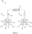
- landing gear assembly 200 is shown in a front view, looking forward to aft, in accordance with various embodiments.
- Landing gear assembly 200 may comprise right landing gear 108 and left landing gear 106.
- Right landing gear 108 may comprise a plurality of wheels, such as a right outboard wheel 202 and a right inboard wheel 204.
- Right outboard wheel 202 may comprise a right outboard brake 206, and right inboard wheel 204 may comprise a right inboard brake 210.
- Right outboard brake 206 and right inboard brake 210 may be mounted in a conventional manner to right outboard wheel 202 and right inboard wheel 204, respectively, to apply and release braking force on a rotatable each respective wheel.
- Right landing gear 108 may further comprise a plurality of sensors, which may include a right outboard (ROB) wheel sensor 208 and a right inboard (RIB) wheel sensor 212.
- ROB wheel sensor 208 and RIB wheel sensor 212 may be coupled to each respective wheel to measure one or more characteristics of each wheel, such as wheel position, wheel speed, and/or wheel acceleration, measured in terms of linear or angular position, linear or angular velocity, linear or angular acceleration, or other measurement unit.
- Left landing gear 106 may comprise a plurality of wheels, such as a left outboard wheel 220 and a left inboard wheel 222.
- Left outboard wheel 220 may comprise a left outboard brake 224
- left inboard wheel 222 may comprise a left inboard brake 228.
- Left outboard brake 224 and left inboard brake 228 may be mounted in a conventional manner to left outboard wheel 220 and left inboard wheel 222, respectively, to apply and release braking force on a rotatable each respective wheel.
- Left landing gear 106 may further comprise a plurality of sensors, which may include a left outboard (LOB) wheel sensor 226 and a left inboard (LIB) wheel sensor 230.
- LOB left outboard
- LIB left inboard
- LOB wheel sensor 226 and LIB wheel sensor 230 may be coupled to each respective wheel to measure one or more characteristics of each wheel, such as wheel position or displacement, wheel speed, and/or wheel acceleration, measured in terms of linear or angular position, linear or angular velocity, linear or angular acceleration, or other measurement unit.
- wheel sensors 226, 230, 208, 212 may comprise wheel speed sensors that output signals indicative of angular velocity or angular displacement, for example, a Hall effect sensor, variable resistance sensor, or the like.
- landing gear assembly 200 is used for example only as aircraft may comprise multiple landing gear and/or multiple wheels and brakes.
- a landing gear may comprise from one to six or more wheels, and a landing gear assembly may comprise from two to twenty or more wheels.
- Each landing gear 106, 108 may comprise a structure, for example a strut, bogie beam, axle and/or other structure, coupled to one or more wheels of the landing gear.
- left landing gear 106 and/or right landing gear 108 further comprises a weight-on-wheels (WOW) sensor 240 configured to detect whether the aircraft is on the ground. After takeoff, for example, a WOW sensor 240 may indicate there is no weight on wheels, thus indicating that the aircraft is in flight, i.e. weight is off wheels, which may be referred to as "weight-off-wheels" (WOFFW).
- WOFFW weight-off-wheels
- WOW sensor 240 may change from an on-ground state to an in-flight state, and thereafter, a gear retract command may be issued to bring the landing gear within the aircraft fuselage.
- Gear retract braking may be used to decelerate the wheels before fully retracting landing gear 106, 108 into the bay within the aircraft fuselage.
- Gear retract braking may comprise a braking technique which assists the deceleration of the wheels of the aircraft by providing additional braking to the wheels after takeoff.
- Gear retract braking may begin after the aircraft wheels are no longer in contact with the ground.
- the wheels begin to decelerate, or "spindown."
- the natural deceleration of the wheels during this time period may be influenced by factors such as the ambient temperature, level of wear on the tire and/or brakes, size and inertia of the wheels, and/or other aircraft characteristics or environmental factors.
- Landing gear assembly 200 may further comprise controller 110 and wheel sensors 208, 212, 230, 226.
- Controller 110 is illustrated in electronic communication (e.g., wired or wirelessly coupled) with right landing gear 108 and left landing gear 106.
- Controller 110 may operate to receive information from wheel sensors 208, 212, 230, 226, which measure a characteristic of wheels 202, 204, 222, 220, and to determine a performance of brakes 206, 210, 228, 224.
- the controller 110 may include or communicate with one or more processors and one or more tangible, non-transitory memories and be capable of implementing logic.
- the processor can be a general purpose processor, a digital signal processor (DSP), an application specific integrated circuit (ASIC), a field programmable gate array (FPGA) or other programmable logic device, discrete gate or transistor logic, discrete hardware components, or a combination thereof.
- DSP digital signal processor
- ASIC application specific integrated circuit
- FPGA field programmable gate array
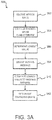
- Controller 110 may be capable of carrying out the steps of FIG. 3A .
- method 300 may be initiated after WOW sensor 240 of landing gear indicates that weight is off wheels, i.e. WOFFW is true. Further, method 300 may be completed prior to the start of gear retract braking.
- Method 300 may be performed by controller 110 and may include the steps of receiving sensor data (step 302), calculating a wheel speed characteristic (step 304), determining a lowest value (step 306), deriving a moving average (step 308), comparing the lowest value to the moving average (step 310), and determining a dragging brake (step 312).
- Step 302 of method 300 may comprise receiving an input of sensor data from one or more sensors, such as WOW sensor 240 and wheel sensors 208, 212, 226, 230.
- Wheel sensors 208, 212, 230, 226 may detect and/or record a series of measurements about the wheels, where the measurements may correlate to wheel speed for each wheel.
- wheel sensors 208, 212, 226, 230 may detect the speed, acceleration, displacement and/or position of wheels 202, 204, 222, 220, respectively, or may measure or detect other characteristics of the wheels.
- wheel sensors 208, 212, 226, 230 may include wheel speed transducers to measure wheel speed directly as an angular or rotational velocity, such as rotations per minute (RPM) or radians per second (rad/s). Data from the sensors may be further processed by controller 110 to calculate the wheel speed characteristic to be used to detect a dragging brake.
- RPM rotations per minute
- rad/s radians per second
- Step 304 of method 300 may comprise calculating a wheel speed characteristic of each wheel by determining a wheel speed, i.e., angular velocity, of each of wheels 202, 204, 222, 220 based on sensor measurements and by further processing the wheel speed, for example, by summation, integration, or the like, into the wheel speed characteristic.
- wheel sensors 208, 212, 226, 230 may measure angular displacement of wheels 202, 204, 222, 220, respectively.
- a measurement of angular displacement over time allows controller 110 to calculate wheel speed (the scalar of angular velocity).
- the acceleration of a wheel may also be derived based on the angular velocity or wheel speed over time.
- Step 304 may comprise a step of filtering or conditioning the data from the sensors. Conditioning of data may be realized by summation, integration and/or other filtering method. Step 304 may comprise calculating a sum of the sensor measurements or conditioned sensor measurements over a time interval to obtain a value for each wheel, wherein the value represents the wheel characteristic, which may be expressed as a magnitude of the total wheel displacement during the time interval.
- the wheel speed characteristic may comprise, for example, a filtered measurement of angular velocity, such as an integral or sum of angular velocity over a time interval.
- step 304 may comprise calculating a time duration for each wheel to "spindown" until the wheel speed is zero, wherein the wheel speed characteristic may comprise a wheel spindown duration or a wheel stop time.
- Step 304 may comprise determining a wheel speed at a selected time point, wherein the wheel speed characteristic may comprise angular velocity of a wheel or wheel speed.
- Step 304 may further comprise selecting a time point based on a spindown duration or a stop time of one or more wheels.
- the selected time point may be a time Ti that a first wheel reaches a wheel speed of zero, a time T f that a final wheel reaches a wheel speed of zero or a time that any wheel of the landing gear reaches a wheel speed of zero.
- Step 306 of method 300 may comprise determining the lowest calculated value of the wheel speed characteristic by comparing the values for each wheel, measured and/or calculated during the present takeoff (or takeoff event), to identify the lowest value of the wheel speed characteristic.
- the lowest value of the wheel speed characteristic may include the lowest wheel speed at a selected time point, the lowest wheel speed sum or integral over a time interval, the shortest time for the wheel speed to reach zero, or other characteristic.
- the lowest value includes a time duration for one of the plurality of wheels to reach a wheel speed of zero.
- Step 308 of method 300 may comprise deriving a moving average of any of the non-lowest calculated values of the wheel speed characteristic by selecting a subset of the calculated values from step 304 of the present takeoff and averaging the subset of the calculated values.
- the subset of calculated values excludes the lowest calculated value identified in step 306.
- the subset of calculated values may further exclude other calculated values, such as the highest value, a plurality of lowest values, a plurality of highest values, or other values. From the remaining sums, excluding the lowest value, the remaining values may be averaged to find an average wheel speed characteristic for the present takeoff, i.e., a present average of the wheel speed characteristics.
- step 308 may include averaging a wheel speed characteristic of the remaining wheels of the plurality of wheels.
- the average wheel speed characteristic may include an average time duration for the wheels to reach a wheel speed of zero or may include an average wheel speed at time T i .
- Step 308 may further include selecting a set of average wheel speed characteristics stored from past takeoffs, and using the past averages and the present average to calculate a new average, i.e., a moving average of the wheel characteristic.
- stored averages from the five (5) to fifteen (15) most recent past takeoffs from the aircraft may be averaged with the present average to calculate the moving average.
- Stored averages from past takeoffs by the aircraft may be selected based on the age of the stored average data. For example, stored averages from past takeoffs may be included in the moving average calculation unless the stored average was recorded before a threshold date or time cutoff, in order to improve the accuracy of the moving average by including data from recent past takeoffs.
- a new moving average may be derived using the subset of stored averages from recent takeoffs, wherein the oldest stored average in the subset is omitted and the new average from the present takeoff is included in each new moving average, such that the moving average may be updated with each new takeoff.
- any number of stored averages from past takeoffs from the aircraft or other aircrafts may be included in the moving average.
- Step 310 of method 300 may comprise comparing the lowest calculated value (from step 306) and the moving average (from step 308) to find a difference between the lowest calculated value and the moving average of the wheel characteristic.
- the difference may be expressed in terms of magnitude of the difference between the lowest value and the moving average, a percentage of the difference between the lowest value and the moving average, or other quantification or comparison of the lowest value, the moving average, past averages and/or the present average.
- the comparison or difference between the lowest value and the moving average may be further evaluated against a threshold.
- the threshold may be based, in part, on the moving average, past averages and/or the present average.
- the threshold may be further based on various information pertaining to the aircraft, such as weight, make, model, and aircraft brake system configuration.
- step 310 may include comparing an average time duration to the lowest value, which may be the shortest time duration for wheel to reach a wheel speed of zero.
- Step 310 may include comparing an average wheel speed to the lowest value, which may be zero at time T i . The comparison or difference between the lowest value and the moving average may be further evaluated against a threshold.
- Step 312 of method 300 may comprise determining a dragging brake by evaluating if the result of the comparison for the wheel characteristic, for example between the lowest calculated wheel value and the moving average, is outside the threshold. If the result is outside the threshold, then it can be concluded that a dragging brake is occurring, and if the result is inside the threshold, then it can be concluded that a dragging brake is not occurring. In response to detecting a dragging brake, controller 110 may send a notification signal to alert the presence of a dragging brake.
- controller 110 may continually receive information from wheel sensors 208, 212, 230, 226 and WOW sensor 240, such as prior to, during, and after takeoff. Controller 110 may be configured to perform dragging brake detection after takeoff and before the start of gear retract braking. After takeoff, WOW sensor 240 indicates that there is no longer WOW and the aircraft is in flight.
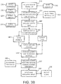
- Controller 110 may perform the steps of receiving a WOFFW signal 320 (step 319), selecting a time interval 322 (step 321), integrating or summing the sensor data over the time interval (step 324), identifying and excluding the lowest sum (step 340), averaging any of the non-lowest sums (step 342), storing the average (step 344), deriving a moving average (step 346), comparing the lowest sum to the moving average (step 348), determining a threshold (step 350), evaluating the lowest sum and the moving average against the threshold (step 352), determining a dragging brake (step 354), outputting a signal (step 356).
- controller 110 may select a time interval 322 for detecting a dragging brake.
- the time interval 322 may begin after the start of WOFFW signal 320 and may end prior to gear retract braking.
- Controller 110 may process the data received from wheel sensors 208, 212, 230, 226 during time interval 322 in order to determine if a dragging brake is present in the brakes for one or more wheels.
- a wheel speed i.e., an angular velocity
- controller 110 may be filtered by controller 110, to obtain a wheel speed, i.e., an angular velocity, for each wheel.
- a wheel speed i.e., an angular velocity
- controller 110 may be filtered by controller 110, to obtain a wheel speed, i.e., an angular velocity, for each wheel.
- a wheel speed i.e., an angular velocity
- an integral or sum of the sensor data for each wheel may be calculated by controller 110 for the time interval 322 (step 324).
- Time interval 322 may be selected to be between receipt of WOFFW signal 320 and gear retract braking 360.
- Step 324 may include a summation of the angular velocity over time interval 322, for example, to determine a sum of the data for each wheel during the time interval 322.
- the time interval 322 may start at any point after receipt of WOFFW signal 320.
- Time interval 322 may begin after a time delay 330 after receipt of WOFFW signal 320.
- the angular velocity of each wheel may be integrated to find the integral of the angular velocity measurements during time interval 322, i.e.
- step 324 may result in a value for each of wheels 202, 204, 222, 220, wherein the resulting value may be a magnitude of the sum of the angular velocity measurements for each wheel: ⁇ 0 n ⁇ LOB , ⁇ 0 n ⁇ LIB , ⁇ 0 n ⁇ RIB , ⁇ 0 n ⁇ ROB Where n is the time interval; and ⁇ is angular velocity, such that ⁇ LOB is the angular velocity of left outboard wheel 220, ⁇ LIB is the angular velocity of left inboard wheel 222, ⁇ ROB is the angular velocity of right outboard wheel 202, and ⁇ RIB is the angular velocity of right inboard wheel 222.
- controller 110 may identify and extract the lowest angular velocity sum from the values resulting from step 324.
- the lowest sum may be extracted and/or segregated from the remaining sums.
- the lowest value may represent a wheel with the lowest velocity sum over the time interval 322, or stated differently, the lowest velocity sum may represent a wheel that completed the fewest rotations over the time interval 322, and thus may represent the wheel with the greatest deceleration.
- FIG. 4 shows wheel sensors 208, 212, 230, 226 having respective wheel velocity profiles 208', 212', 230', 226'. For illustration purposes, FIG. 4 shows wheel sensor 230 having a dragging brake velocity profile, shown by wheel velocity profile 230'.
- FIG. 3B shows that the lowest sum may be omitted from steps 342, 344 and 346.
- controller 110 may average the sums from the summation of angular velocity to determine an average angular velocity sum for the present takeoff.
- the lowest angular velocity sum identified in step 340 may be omitted from the calculation of the average angular velocity sum. In various embodiments, other angular velocity sums may be omitted from the average.
- ⁇ AvgSumNew is the average of the non-lowest angular velocity sums for a takeoff, i.e., the average angular velocity sum
- n is the time interval
- ⁇ x , ⁇ y and ⁇ z are angular velocity profiles for the non-lowest wheel velocities, where as illustrated in the example of FIG. 4 , ⁇ x , ⁇ y and ⁇ z may be angular velocity data from wheel sensors 208, 212, and 226.
- the average angular velocity sum for the present takeoff may be stored by the controller 110 as stored data, such as stored average angular velocity sums 345 ( FIG. 5 ).
- Controller 110 may contain stored data from previous or past takeoffs for the aircraft and/or other aircrafts, such as stored average angular velocity sums 345 ( FIG. 5 ).
- a moving average may be derived from average angular velocity sums from the present takeoff and from past takeoffs, which also may be referred to as past or present "takeoff events.”
- a subset 347 of stored average angular velocity sums 345 may be selected to calculate the moving average.
- ten (10) average angular velocity sums are used to derive a moving average of the angular velocity sums.
- the ten (10) data points may include a subset 347 of nine (9) of the stored average angular velocity sums from the previous nine (9) takeoffs with one of the ten (10) data points including the average angular velocity sum for the present takeoff (from step 342).
- the nine (9) stored average angular velocity sums and the one (1) present average angular velocity sum may be used to derive a 10-event moving average.
- a 10-event moving average calculation of average angular velocity sum may be represented as: ⁇ n + x n + x + 10 ⁇ MovingAvg ⁇ ⁇ Avg Sum old + ⁇ Avg Sum new
- FIG. 5 illustrates the moving average calculation, where ⁇ AvgSumOld is the average angular velocity sum from the tenth previous takeoff, and where ⁇ AvgSumNew is the average angular velocity sum for the present takeoff, and ⁇ MovingAvg is the previous moving average for the angular velocity sums.
- ⁇ MovingAvgNew shown in FIG. 5
- ⁇ AvgSumOld is deleted from the new moving average calculation and ⁇ AvgSumNew is added into the new moving average calculation.
- a moving average for the aircraft landing gear such as right landing gear 108, left landing gear 106, and/or landing gear assembly 200 (from FIG. 2 ), may be updated with a new moving average calculation after each takeoff.
- the lowest angular velocity sum (from step 340) may be compared to the new moving average (from step 346).
- comparing the lowest angular velocity sum to the new moving average may comprise determining a variation, deviation, or a difference between the lowest sum and the new moving average.
- a large difference between the lowest angular velocity sum and the new moving average may indicate a dragging brake.
- the comparison may be represented generally as: ⁇ lowest sum ⁇ ⁇ RollingAvg new Where ⁇ LowestSum is the lowest angular velocity sum from the present takeoff; and ⁇ MovingAvgNew is the new 10-event moving average calculation.
- the comparison of lowest angular velocity sum and moving average may be evaluated against a threshold.
- An angular velocity sum beyond a given threshold value may indicate a dragging brake.
- the threshold may be predetermined, in part, and may further be based on the new moving average.
- threshold may be determined based upon aircraft size, weight, engine power, brake type, brake size, and/or other suitable factors.
- the threshold may be a minimum percentage of the moving average.
- a threshold value may range from about 40% to 70% of the moving average, more preferably from about 50% to about 70% of the moving average and more preferably from about 50% to about 60% of the moving average, wherein "about" in this context only means +/- 5%.
- a threshold based on a predetermined value of 50% of the moving average may be represented as: ⁇ lowest sum ⁇ 1 2 ⁇ ⁇ MovingAvg new Where ⁇ LowestSum is the lowest angular velocity sum from the present takeoff; and ⁇ MovingAvgNew is the new 10-event moving average.
- a dragging brake may be determined if the lowest angular velocity sum is outside the threshold. For example, if the lowest angular velocity sum is less than 50% of the new moving average, the lowest angular velocity sum is outside the threshold and may indicate a dragging brake. Thus, a wheel speed characteristic that falls below the minimum threshold value, for example of 50% of the moving average, may indicate that a dragging brake is present.
- a threshold based on the moving average for an aircraft may better account for the condition of the tires and brakes.
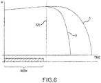
- FIG. 6 angular velocity profiles for a new wheel assembly A, having a new tire and/or brake, and a worn wheel assembly B, having a worn tire and brake, is illustrated, in accordance with various embodiments.
- FIG. 6 generally shows that the natural spindown for new wheel assembly A is different than the natural spindown for worn wheel assembly B.
- a threshold based on a moving average better accounts for the changing velocity profiles caused by the slow wear on tires and brakes over time. For example, a dragging brake detection threshold that is based on a velocity profile of new wheel assembly A would be less accurate for detecting a dragging brake in a worn wheel assembly B.
- a threshold based on a moving average more accurately detects a dragging brake over the life of the tires and brakes. Where worn tires and brakes are replaced and the velocity profile changes of the wheel assembly changes, a threshold based on a moving average still provides a conservative test for a dragging brake.
- controller 110 may produce an output signal indicative of a dragging brake to another aircraft component.
- controller 110 may send a dragging brake signal to a cockpit component.
- a cockpit component may be any system that delivers information to the cockpit.
- a cockpit component may cause a light, icon, graphic, or other visual or audio representation to appear in the cockpit to indicate a dragging brake.
- the aircraft pilot or other crew member may then take remedial action based upon the dragging brake signal. For example, a pilot may delay landing gear retraction until it is believed that the dragging brake has cooled.
- Controller 110 may be capable of carrying out the steps of FIG. 7 .
- method 400 may be initiated after WOW sensor 240 of landing gear indicates that weight is off wheels, i.e. WOFFW is true.
- Step 404 may comprise determining a time T that one of the plurality of wheels reaches a wheel speed of zero.
- the time T may be a time T i that a first wheel reaches a wheel speed of zero, a time T f that a final wheel reaches a wheel speed of zero or a time that any wheel of the landing gear reaches a wheel speed of zero.
- the wheel with a wheel speed of zero at time T may be identified as the selected wheel.
- Step 406 may comprise calculating a wheel speed characteristic for each of a plurality of wheels 202, 204, 222, 220 of the landing gear.
- Step 406 may comprise determining a wheel speed at time T, wherein the wheel speed characteristic may comprise an angular velocity of a wheel or a wheel speed.
- Step 406 may comprise calculating a time duration for each wheel to completely spindown until the wheel speed is zero, wherein the wheel speed characteristic may comprise a wheel spindown duration or a wheel stop time.
- Step 408 may comprise identifying a lowest value of the wheel speed characteristic and omitting the lowest value, and deriving an average wheel speed characteristic.
- Step 408 may comprise calculating a wheel speed characteristic of the other wheels of the plurality of wheels at time T i , omitting the selected wheel identified in step 404.
- Step 408 may comprise determining an average wheel speed characteristic for the present takeoff, and may further include determining a moving average of the wheel speed characteristic based on the present takeoff and past takeoffs.
- Step 410 may comprise evaluating the average wheel speed characteristic for the present takeoff.
- step 410 may include comparing the average wheel speed characteristic to the wheel speed characteristic of the selected wheel identified in step 404.
- step 410 may include comparing the average wheel speed characteristic to the lowest value, which may be the shortest time duration for wheel to reach a wheel speed of zero.
- Step 410 may include evaluating an average time duration for the wheels to stop spinning compared to the time duration between WOFFW until time T, which may be the time duration for the selected wheel identified in step 404 stop spinning.
- Step 410 may include evaluating an average wheel speed at time T to a wheel speed of zero.
- step 410 may further comprise calculating a difference between the wheel speed characteristic and the wheel speed characteristic of the selected wheel identified in step 404.
- Step 410 may comprise evaluating the difference against a threshold.
- Step 412 may comprise determining a dragging brake by evaluating the average wheel speed characteristic against a threshold, and determining if the average wheel speed characteristic at time T is outside the threshold. If the result is outside the threshold, then it can be concluded that a dragging brake is occurring, and if the result is inside the threshold, then it can be concluded that a dragging brake is not occurring.
- controller 110 may send a notification signal to alert the presence of a dragging brake.
Landscapes
- Engineering & Computer Science (AREA)
- Aviation & Aerospace Engineering (AREA)
- Mechanical Engineering (AREA)
- Transportation (AREA)
- Manufacturing & Machinery (AREA)
- Regulating Braking Force (AREA)
Claims (13)
- Fahrwerksbaugruppe (200), umfassend:ein erstes Rad und ein zweites Rad;einen ersten Radsensor, der an das erste Rad gekoppelt ist, und einen zweiten Radsensor, der an das zweite Rad gekoppelt ist;eine Steuerung (110), die an den ersten Radsensor und den zweiten Radsensor gekoppelt ist; undeinen greifbaren, nichttransitorischen Speicher, der dazu konfiguriert ist, mit der Steuerung zu kommunizieren, wobei der greifbare, nichttransitorische Speicher Anweisungen aufweist, die auf ihm gespeichert sind, die als Reaktion auf die Ausführung durch die Steuerung die Steuerung (110) veranlassen, Vorgänge durchzuführen, die Folgendes umfassen:Empfangen (302) von Daten von dem ersten Radsensor und dem zweiten Radsensor durch die Steuerung (110);Berechnen (304) eines Raddrehzahlmerkmals für jedes des ersten Rads und des zweiten Rads basierend auf den Daten durch die Steuerung (110);Identifizieren (306) eines niedrigsten Werts für das Raddrehzahlmerkmal des ersten Rads und des zweiten Rads durch die Steuerung (110);Bestimmen (308) eines gleitenden Durchschnitts für das Raddrehzahlmerkmal des ersten Rads und des zweiten Rads durch die Steuerung (110);Vergleichen (310) des niedrigsten Werts mit dem gleitenden Durchschnitt des ersten Rads und des zweiten Rads durch die Steuerung (110); undBestimmen (312) durch die Steuerung (110), ob der niedrigste Wert für das Raddrehzahlmerkmal des ersten Rads und des zweiten Rads eine schleifende Bremse anzeigt, und Generieren (356) eines Signals basierend auf dem Vorliegen der schleifenden Bremse durch die Steuerung (110).
- Fahrwerksbaugruppe nach Anspruch 1, wobei die Vorgänge ferner Folgendes umfassen:Bestimmen eines durchschnittlichen Raddrehzahlmerkmals für einen gegenwärtigen Start durch die Steuerung (110), wobei der niedrigste Wert von dem Durchschnitt ausgeschlossen ist; undSpeichern des durchschnittlichen Raddrehzahlmerkmals für den gegenwärtigen Start durch die Steuerung (110), wobei der gleitende Durchschnitt auf dem durchschnittlichen Raddrehzahlmerkmal für den gegenwärtigen Start beruht und auf einem gespeicherten durchschnittlichen Raddrehzahlmerkmal von einem vergangenen Start beruht.
- Fahrwerksbaugruppe nach Anspruch 2, wobei die Vorgänge ferner das Beurteilen (352) des niedrigsten Werts und des gleitenden Durchschnitts anhand eines Schwellenwerts durch die Steuerung (110) umfassen, wobei der Schwellenwert auf dem gleitenden Durchschnitt beruht, und
wobei der Schwellenwert bevorzugt 50 % bis 70 % des gleitenden Durchschnitts ist. - Fahrwerksbaugruppe nach einem der vorhergehenden Ansprüche, wobei die Daten eine Verdrängung, Geschwindigkeit oder Beschleunigung beinhalten, und wobei das Raddrehzahlmerkmal eine Summierung der Daten während eines Zeitintervalls ist, und wobei das Zeitintervall bevorzugt nach dem Start beginnt und vor einem Fahrwerkseinziehbremsen endet.
- Herstellungsartikel, der ein nichttransitorisches, greifbares computerlesbares Speichermedium beinhaltet, das auf ihm gespeicherte Anweisungen aufweist, die als Reaktion auf die Ausführung durch eine Steuerung (110) die Steuerung (110) veranlassen, Vorgänge durchzuführen, die Folgendes umfassen:Empfangen von Daten von einem ersten Radsensor, der an ein erstes Rad eines Fahrwerks gekoppelt ist, und einem zweiten Radsensor, der an ein zweites Rad des Fahrwerks gekoppelt ist, durch die Steuerung;Berechnen (304) eines Raddrehzahlmerkmals für das erste Rad und das zweite Rad basierend auf den Daten durch die Steuerung (110);Identifizieren (306) eines niedrigsten Werts für das Raddrehzahlmerkmal des ersten Rads und des zweiten Rads durch die Steuerung (110);Bestimmen (308) eines gleitenden Durchschnitts für das Raddrehzahlmerkmal des ersten Rads und des zweiten Rads durch die Steuerung (110);Vergleichen (310) des niedrigsten Werts mit dem gleitenden Durchschnitt des ersten Rads und des zweiten Rads durch die Steuerung (110); undBestimmen (312) durch die Steuerung (110), ob der niedrigste Wert für das Raddrehzahlmerkmal des ersten Rads und des zweiten Rads eine schleifende Bremse anzeigt, und Generieren (356) eines Signals basierend auf dem Vorliegen der schleifenden Bremse durch die Steuerung (110).
- Herstellungsartikel nach Anspruch 5, wobei die Vorgänge ferner Folgendes umfassen:Bestimmen (342) eines durchschnittlichen Raddrehzahlmerkmals für einen gegenwärtigen Start durch die Steuerung, wobei der niedrigste Wert von dem Durchschnitt ausgeschlossen ist; undSpeichern (344) des durchschnittlichen Raddrehzahlmerkmals für den gegenwärtigen Start durch die Steuerung, wobei der gleitende Durchschnitt auf dem durchschnittlichen Raddrehzahlmerkmal für den gegenwärtigen Start beruht und auf einem gespeicherten durchschnittlichen Raddrehzahlmerkmal von einem vergangenen Start beruht, undwobei die Vorgänge ferner bevorzugt das Beurteilen (352) des niedrigsten Werts und des gleitenden Durchschnitts anhand eines Schwellenwerts durch die Steuerung umfassen, wobei der Schwellenwert auf dem gleitenden Durchschnitt beruht, undwobei der Schwellenwert bevorzugt 50 % bis 70 % des gleitenden Durchschnitts ist.
- Herstellungsartikel nach Anspruch 5, wobei das Raddrehzahlmerkmal eine Summierung einer Winkelgeschwindigkeit während eines Zeitintervalls ist, und
wobei das Zeitintervall bevorzugt nach dem Start beginnt und vor einem Fahrwerkseinziehbremsen endet. - Verfahren zum Detektieren einer schleifenden Bremse, wobei das Verfahren Folgendes umfasst.
Empfangen von Daten von einem ersten Radsensor und einem zweiten Radsensor eines Fahrwerks durch eine Steuerung;
Berechnen eines Raddrehzahlmerkmals für jedes eines ersten Rads und eines zweiten Rads des Fahrwerks basierend auf den Daten durch die Steuerung;
Identifizieren eines niedrigsten Werts für das Raddrehzahlmerkmal des ersten Rads und des zweiten Rads durch die Steuerung (110);
Bestimmen (346) eines gleitenden Durchschnitts für das Raddrehzahlmerkmal des ersten Rads und des zweiten Rads durch die Steuerung;
Vergleichen (348) des niedrigsten Werts mit dem gleitenden Durchschnitt des ersten Rads und des zweiten Rads durch die Steuerung; und
Bestimmen (354) durch die Steuerung, ob der niedrigste Wert für das Raddrehzahlmerkmal eine schleifende Bremse des ersten Rads und des zweiten Rads anzeigt, und Generieren eines Signals basierend auf dem Vorliegen der schleifenden Bremse durch die Steuerung. - Verfahren nach Anspruch 8, ferner umfassend:Bestimmen (342) eines durchschnittlichen Raddrehzahlmerkmals für einen gegenwärtigen Start durch die Steuerung (110), wobei der niedrigste Wert von dem Durchschnitt ausgeschlossen ist; undSpeichern (344) des durchschnittlichen Raddrehzahlmerkmals für den gegenwärtigen Start durch die Steuerung (110), wobei der gleitende Durchschnitt auf dem durchschnittlichen Raddrehzahlmerkmal für den gegenwärtigen Start beruht und auf einem gespeicherten durchschnittlichen Raddrehzahlmerkmal von einem vergangenen Start beruht.
- Verfahren nach Anspruch 9, ferner umfassend Beurteilen des niedrigsten Werts und des gleitenden Durchschnitts anhand eines Schwellenwerts durch die Steuerung (110), wobei der Schwellenwert auf dem gleitenden Durchschnitt beruht.
- Verfahren nach Anspruch 9 oder 10, wobei der Schwellenwert 50 % bis 70 % des gleitenden Durchschnitts ist.
- Verfahren nach Anspruch 8, wobei das Raddrehzahlmerkmal eine Summierung einer Winkelgeschwindigkeit während eines Zeitintervalls ist.
- Verfahren nach Anspruch 12, wobei das Zeitintervall nach dem Start beginnt und vor einem Fahrwerkseinziehbremsen endet.
Applications Claiming Priority (1)
| Application Number | Priority Date | Filing Date | Title |
|---|---|---|---|
| US15/180,663 US10005566B2 (en) | 2016-06-13 | 2016-06-13 | Systems and methods for detection of dragging brake |
Publications (2)
| Publication Number | Publication Date |
|---|---|
| EP3257712A1 EP3257712A1 (de) | 2017-12-20 |
| EP3257712B1 true EP3257712B1 (de) | 2021-03-17 |
Family
ID=59101272
Family Applications (1)
| Application Number | Title | Priority Date | Filing Date |
|---|---|---|---|
| EP17175809.7A Active EP3257712B1 (de) | 2016-06-13 | 2017-06-13 | Systeme und verfahren zur detektion einer schleifenden bremse |
Country Status (2)
| Country | Link |
|---|---|
| US (1) | US10005566B2 (de) |
| EP (1) | EP3257712B1 (de) |
Families Citing this family (18)
| Publication number | Priority date | Publication date | Assignee | Title |
|---|---|---|---|---|
| US11358710B2 (en) * | 2018-02-23 | 2022-06-14 | The Boeing Company | Methods and apparatus for controlling landing gear retract braking |
| US10933982B2 (en) * | 2018-02-26 | 2021-03-02 | The Boeing Company | Methods and apparatus for controlling landing gear retract braking |
| US10730491B2 (en) * | 2018-04-20 | 2020-08-04 | Goodrich Corporation | Energy-based antiskid brake control system |
| US10882500B2 (en) | 2018-11-30 | 2021-01-05 | Raytheon Technologies Corporation | Systems and methods for brake failure detection using retract braking |
| US20200172077A1 (en) * | 2018-11-30 | 2020-06-04 | Goodrich Corporation | Temperature monitoring to detect brake failure |
| US20200207318A1 (en) * | 2019-01-02 | 2020-07-02 | Caterpillar Inc. | Brake dragging detection and mitigation |
| GB2583486A (en) * | 2019-04-29 | 2020-11-04 | Airbus Operations Ltd | Brake characteristics |
| CN110589019B (zh) * | 2019-09-09 | 2021-07-13 | 中国航空工业集团公司北京长城航空测控技术研究所 | 一种起落架高速收放试验的力加载方法及加载装置 |
| GB2587205A (en) * | 2019-09-17 | 2021-03-24 | Airbus Operations Ltd | Aircraft system |
| CN110816887B (zh) * | 2019-11-25 | 2023-10-24 | 西安航空制动科技有限公司 | 一种飞机机轮刹车系统试验台架及试验方法 |
| US12128863B2 (en) * | 2020-05-11 | 2024-10-29 | Goodrich Corporation | Detection of brake failure using wheel speed during landing gear retraction |
| GB2604182A (en) * | 2021-02-26 | 2022-08-31 | Airbus Operations Ltd | Aircraft system |
| GB2606205A (en) * | 2021-04-29 | 2022-11-02 | Airbus Operations Ltd | Aircraft braking controller and system |
| US12043240B2 (en) * | 2021-12-13 | 2024-07-23 | Goodrich Corporation | Erroneous velocity data detection algorithm systems and methods |
| GB2617065A (en) * | 2022-03-25 | 2023-10-04 | Airbus Operations Ltd | Monitoring friction associated with a plurality of aircraft wheels |
| CN114754999A (zh) * | 2022-05-16 | 2022-07-15 | 广东粤港澳大湾区黄埔材料研究院 | 一种飞机起落架机轮刹车响应试验装置及试验方法 |
| US12576823B2 (en) * | 2023-12-19 | 2026-03-17 | Goodrich Corporation | Brake coefficient of friction (μ) estimation for prognostics and health management (PHM) and improved load balance (LB) |
| US20250289565A1 (en) * | 2024-03-15 | 2025-09-18 | The Boeing Company | Systems and methods for monitoring a gear retract braking load alleviation system |
Family Cites Families (8)
| Publication number | Priority date | Publication date | Assignee | Title |
|---|---|---|---|---|
| GB565052A (en) | 1942-07-22 | 1944-10-25 | George Herbert Dowty | Improvements in leg structures for mounting aircraft landing elements |
| FR1033176A (fr) | 1951-02-27 | 1953-07-08 | Constructions Aeronautiques Sudest | Perfectionnements aux amortisseurs pour trains d'atterrissage, notamment pour aérodynes de gros tonnage |
| GB1040424A (en) | 1963-10-28 | 1966-08-24 | Electro Hydraulics Ltd | Aircraft undercarriages |
| US7441844B2 (en) * | 2005-02-18 | 2008-10-28 | Hydro-Aire, Inc. | Method to reduce carbon brake wear through residual brake force |
| US8102280B2 (en) | 2009-03-03 | 2012-01-24 | Goodrich Corporation | System and method for detecting a dragging brake |
| US8843254B2 (en) | 2012-07-11 | 2014-09-23 | Goodrich Corporation | Systems and methods for dragging brake detection |
| US9302767B2 (en) | 2012-11-12 | 2016-04-05 | Gulfstream Aerospace Corporation | Nose landing gear arrangement for aircraft and method of assembly |
| US8666625B1 (en) | 2012-11-13 | 2014-03-04 | Hamilton Sundstrand Corporation | Automatic adjustment of electric brake actuators for a dragging brake condition |
-
2016
- 2016-06-13 US US15/180,663 patent/US10005566B2/en active Active
-
2017
- 2017-06-13 EP EP17175809.7A patent/EP3257712B1/de active Active
Non-Patent Citations (1)
| Title |
|---|
| None * |
Also Published As
| Publication number | Publication date |
|---|---|
| US10005566B2 (en) | 2018-06-26 |
| EP3257712A1 (de) | 2017-12-20 |
| US20170355473A1 (en) | 2017-12-14 |
Similar Documents
| Publication | Publication Date | Title |
|---|---|---|
| EP3257712B1 (de) | Systeme und verfahren zur detektion einer schleifenden bremse | |
| EP2684752B1 (de) | Verfahren zur Erfassung eines gebremsten Rads | |
| US10882500B2 (en) | Systems and methods for brake failure detection using retract braking | |
| US11364884B2 (en) | Selective braking of carbon brakes to improve life | |
| CN108382384B (zh) | 基于制动器扭矩和温度的故障检测 | |
| US7946165B2 (en) | Over-speed, rough loads and hard landing detection system | |
| EP3403892B1 (de) | Beurteilung der oberflächenbedingungen von start- und landebahnen | |
| US10759524B2 (en) | Antiskid operation during degraded operation | |
| EP3556619B1 (de) | Energiebasiertes antiblockierbremssteuerungssystem | |
| EP4180287B1 (de) | Systeme und verfahren zur überwachung des zustands von bremsen | |
| EP2565093A1 (de) | Systeme und Verfahren zum Testen eines Bremssystems | |
| EP3357772B1 (de) | Hydraulische parkbremsanlage und verfahren | |
| US11970151B2 (en) | Systems and methods for aircraft antiskid braking | |
| US11492103B2 (en) | Distributed brake control systems and methods for high efficiency antiskid performance | |
| EP3909818B1 (de) | Erkennung von bremsversagen unter verwendung der radgeschwindigkeit beim einfahren des fahrwerks | |
| CN120024501A (zh) | 用于监测飞行器的起落架的制动器的温度的方法 |
Legal Events
| Date | Code | Title | Description |
|---|---|---|---|
| PUAI | Public reference made under article 153(3) epc to a published international application that has entered the european phase |
Free format text: ORIGINAL CODE: 0009012 |
|
| STAA | Information on the status of an ep patent application or granted ep patent |
Free format text: STATUS: THE APPLICATION HAS BEEN PUBLISHED |
|
| AK | Designated contracting states |
Kind code of ref document: A1 Designated state(s): AL AT BE BG CH CY CZ DE DK EE ES FI FR GB GR HR HU IE IS IT LI LT LU LV MC MK MT NL NO PL PT RO RS SE SI SK SM TR |
|
| AX | Request for extension of the european patent |
Extension state: BA ME |
|
| STAA | Information on the status of an ep patent application or granted ep patent |
Free format text: STATUS: REQUEST FOR EXAMINATION WAS MADE |
|
| 17P | Request for examination filed |
Effective date: 20180620 |
|
| RBV | Designated contracting states (corrected) |
Designated state(s): AL AT BE BG CH CY CZ DE DK EE ES FI FR GB GR HR HU IE IS IT LI LT LU LV MC MK MT NL NO PL PT RO RS SE SI SK SM TR |
|
| RIC1 | Information provided on ipc code assigned before grant |
Ipc: B60T 17/22 20060101ALI20200720BHEP Ipc: B60T 8/17 20060101AFI20200720BHEP |
|
| GRAP | Despatch of communication of intention to grant a patent |
Free format text: ORIGINAL CODE: EPIDOSNIGR1 |
|
| STAA | Information on the status of an ep patent application or granted ep patent |
Free format text: STATUS: GRANT OF PATENT IS INTENDED |
|
| INTG | Intention to grant announced |
Effective date: 20201014 |
|
| GRAS | Grant fee paid |
Free format text: ORIGINAL CODE: EPIDOSNIGR3 |
|
| GRAA | (expected) grant |
Free format text: ORIGINAL CODE: 0009210 |
|
| STAA | Information on the status of an ep patent application or granted ep patent |
Free format text: STATUS: THE PATENT HAS BEEN GRANTED |
|
| AK | Designated contracting states |
Kind code of ref document: B1 Designated state(s): AL AT BE BG CH CY CZ DE DK EE ES FI FR GB GR HR HU IE IS IT LI LT LU LV MC MK MT NL NO PL PT RO RS SE SI SK SM TR |
|
| REG | Reference to a national code |
Ref country code: GB Ref legal event code: FG4D |
|
| REG | Reference to a national code |
Ref country code: CH Ref legal event code: EP |
|
| REG | Reference to a national code |
Ref country code: DE Ref legal event code: R096 Ref document number: 602017034619 Country of ref document: DE |
|
| REG | Reference to a national code |
Ref country code: IE Ref legal event code: FG4D |
|
| REG | Reference to a national code |
Ref country code: AT Ref legal event code: REF Ref document number: 1371962 Country of ref document: AT Kind code of ref document: T Effective date: 20210415 |
|
| REG | Reference to a national code |
Ref country code: LT Ref legal event code: MG9D |
|
| PG25 | Lapsed in a contracting state [announced via postgrant information from national office to epo] |
Ref country code: GR Free format text: LAPSE BECAUSE OF FAILURE TO SUBMIT A TRANSLATION OF THE DESCRIPTION OR TO PAY THE FEE WITHIN THE PRESCRIBED TIME-LIMIT Effective date: 20210618 Ref country code: HR Free format text: LAPSE BECAUSE OF FAILURE TO SUBMIT A TRANSLATION OF THE DESCRIPTION OR TO PAY THE FEE WITHIN THE PRESCRIBED TIME-LIMIT Effective date: 20210317 Ref country code: FI Free format text: LAPSE BECAUSE OF FAILURE TO SUBMIT A TRANSLATION OF THE DESCRIPTION OR TO PAY THE FEE WITHIN THE PRESCRIBED TIME-LIMIT Effective date: 20210317 Ref country code: NO Free format text: LAPSE BECAUSE OF FAILURE TO SUBMIT A TRANSLATION OF THE DESCRIPTION OR TO PAY THE FEE WITHIN THE PRESCRIBED TIME-LIMIT Effective date: 20210617 Ref country code: BG Free format text: LAPSE BECAUSE OF FAILURE TO SUBMIT A TRANSLATION OF THE DESCRIPTION OR TO PAY THE FEE WITHIN THE PRESCRIBED TIME-LIMIT Effective date: 20210617 |
|
| REG | Reference to a national code |
Ref country code: AT Ref legal event code: MK05 Ref document number: 1371962 Country of ref document: AT Kind code of ref document: T Effective date: 20210317 |
|
| REG | Reference to a national code |
Ref country code: NL Ref legal event code: MP Effective date: 20210317 |
|
| PG25 | Lapsed in a contracting state [announced via postgrant information from national office to epo] |
Ref country code: SE Free format text: LAPSE BECAUSE OF FAILURE TO SUBMIT A TRANSLATION OF THE DESCRIPTION OR TO PAY THE FEE WITHIN THE PRESCRIBED TIME-LIMIT Effective date: 20210317 Ref country code: RS Free format text: LAPSE BECAUSE OF FAILURE TO SUBMIT A TRANSLATION OF THE DESCRIPTION OR TO PAY THE FEE WITHIN THE PRESCRIBED TIME-LIMIT Effective date: 20210317 Ref country code: LV Free format text: LAPSE BECAUSE OF FAILURE TO SUBMIT A TRANSLATION OF THE DESCRIPTION OR TO PAY THE FEE WITHIN THE PRESCRIBED TIME-LIMIT Effective date: 20210317 |
|
| PG25 | Lapsed in a contracting state [announced via postgrant information from national office to epo] |
Ref country code: NL Free format text: LAPSE BECAUSE OF FAILURE TO SUBMIT A TRANSLATION OF THE DESCRIPTION OR TO PAY THE FEE WITHIN THE PRESCRIBED TIME-LIMIT Effective date: 20210317 |
|
| PG25 | Lapsed in a contracting state [announced via postgrant information from national office to epo] |
Ref country code: AT Free format text: LAPSE BECAUSE OF FAILURE TO SUBMIT A TRANSLATION OF THE DESCRIPTION OR TO PAY THE FEE WITHIN THE PRESCRIBED TIME-LIMIT Effective date: 20210317 Ref country code: SM Free format text: LAPSE BECAUSE OF FAILURE TO SUBMIT A TRANSLATION OF THE DESCRIPTION OR TO PAY THE FEE WITHIN THE PRESCRIBED TIME-LIMIT Effective date: 20210317 Ref country code: EE Free format text: LAPSE BECAUSE OF FAILURE TO SUBMIT A TRANSLATION OF THE DESCRIPTION OR TO PAY THE FEE WITHIN THE PRESCRIBED TIME-LIMIT Effective date: 20210317 Ref country code: CZ Free format text: LAPSE BECAUSE OF FAILURE TO SUBMIT A TRANSLATION OF THE DESCRIPTION OR TO PAY THE FEE WITHIN THE PRESCRIBED TIME-LIMIT Effective date: 20210317 Ref country code: LT Free format text: LAPSE BECAUSE OF FAILURE TO SUBMIT A TRANSLATION OF THE DESCRIPTION OR TO PAY THE FEE WITHIN THE PRESCRIBED TIME-LIMIT Effective date: 20210317 |
|
| PG25 | Lapsed in a contracting state [announced via postgrant information from national office to epo] |
Ref country code: RO Free format text: LAPSE BECAUSE OF FAILURE TO SUBMIT A TRANSLATION OF THE DESCRIPTION OR TO PAY THE FEE WITHIN THE PRESCRIBED TIME-LIMIT Effective date: 20210317 Ref country code: SK Free format text: LAPSE BECAUSE OF FAILURE TO SUBMIT A TRANSLATION OF THE DESCRIPTION OR TO PAY THE FEE WITHIN THE PRESCRIBED TIME-LIMIT Effective date: 20210317 Ref country code: PT Free format text: LAPSE BECAUSE OF FAILURE TO SUBMIT A TRANSLATION OF THE DESCRIPTION OR TO PAY THE FEE WITHIN THE PRESCRIBED TIME-LIMIT Effective date: 20210719 Ref country code: PL Free format text: LAPSE BECAUSE OF FAILURE TO SUBMIT A TRANSLATION OF THE DESCRIPTION OR TO PAY THE FEE WITHIN THE PRESCRIBED TIME-LIMIT Effective date: 20210317 Ref country code: IS Free format text: LAPSE BECAUSE OF FAILURE TO SUBMIT A TRANSLATION OF THE DESCRIPTION OR TO PAY THE FEE WITHIN THE PRESCRIBED TIME-LIMIT Effective date: 20210717 |
|
| REG | Reference to a national code |
Ref country code: DE Ref legal event code: R097 Ref document number: 602017034619 Country of ref document: DE |
|
| REG | Reference to a national code |
Ref country code: DE Ref legal event code: R119 Ref document number: 602017034619 Country of ref document: DE |
|
| PLBE | No opposition filed within time limit |
Free format text: ORIGINAL CODE: 0009261 |
|
| STAA | Information on the status of an ep patent application or granted ep patent |
Free format text: STATUS: NO OPPOSITION FILED WITHIN TIME LIMIT |
|
| PG25 | Lapsed in a contracting state [announced via postgrant information from national office to epo] |
Ref country code: ES Free format text: LAPSE BECAUSE OF FAILURE TO SUBMIT A TRANSLATION OF THE DESCRIPTION OR TO PAY THE FEE WITHIN THE PRESCRIBED TIME-LIMIT Effective date: 20210317 Ref country code: DK Free format text: LAPSE BECAUSE OF FAILURE TO SUBMIT A TRANSLATION OF THE DESCRIPTION OR TO PAY THE FEE WITHIN THE PRESCRIBED TIME-LIMIT Effective date: 20210317 Ref country code: AL Free format text: LAPSE BECAUSE OF FAILURE TO SUBMIT A TRANSLATION OF THE DESCRIPTION OR TO PAY THE FEE WITHIN THE PRESCRIBED TIME-LIMIT Effective date: 20210317 Ref country code: MC Free format text: LAPSE BECAUSE OF FAILURE TO SUBMIT A TRANSLATION OF THE DESCRIPTION OR TO PAY THE FEE WITHIN THE PRESCRIBED TIME-LIMIT Effective date: 20210317 |
|
| REG | Reference to a national code |
Ref country code: CH Ref legal event code: PL |
|
| 26N | No opposition filed |
Effective date: 20211220 |
|
| PG25 | Lapsed in a contracting state [announced via postgrant information from national office to epo] |
Ref country code: SI Free format text: LAPSE BECAUSE OF FAILURE TO SUBMIT A TRANSLATION OF THE DESCRIPTION OR TO PAY THE FEE WITHIN THE PRESCRIBED TIME-LIMIT Effective date: 20210317 |
|
| REG | Reference to a national code |
Ref country code: BE Ref legal event code: MM Effective date: 20210630 |
|
| PG25 | Lapsed in a contracting state [announced via postgrant information from national office to epo] |
Ref country code: LU Free format text: LAPSE BECAUSE OF NON-PAYMENT OF DUE FEES Effective date: 20210613 |
|
| PG25 | Lapsed in a contracting state [announced via postgrant information from national office to epo] |
Ref country code: LI Free format text: LAPSE BECAUSE OF NON-PAYMENT OF DUE FEES Effective date: 20210630 Ref country code: IT Free format text: LAPSE BECAUSE OF FAILURE TO SUBMIT A TRANSLATION OF THE DESCRIPTION OR TO PAY THE FEE WITHIN THE PRESCRIBED TIME-LIMIT Effective date: 20210317 Ref country code: IE Free format text: LAPSE BECAUSE OF NON-PAYMENT OF DUE FEES Effective date: 20210613 Ref country code: DE Free format text: LAPSE BECAUSE OF NON-PAYMENT OF DUE FEES Effective date: 20220101 Ref country code: CH Free format text: LAPSE BECAUSE OF NON-PAYMENT OF DUE FEES Effective date: 20210630 |
|
| PG25 | Lapsed in a contracting state [announced via postgrant information from national office to epo] |
Ref country code: IS Free format text: LAPSE BECAUSE OF FAILURE TO SUBMIT A TRANSLATION OF THE DESCRIPTION OR TO PAY THE FEE WITHIN THE PRESCRIBED TIME-LIMIT Effective date: 20210717 |
|
| PG25 | Lapsed in a contracting state [announced via postgrant information from national office to epo] |
Ref country code: BE Free format text: LAPSE BECAUSE OF NON-PAYMENT OF DUE FEES Effective date: 20210630 |
|
| PG25 | Lapsed in a contracting state [announced via postgrant information from national office to epo] |
Ref country code: HU Free format text: LAPSE BECAUSE OF FAILURE TO SUBMIT A TRANSLATION OF THE DESCRIPTION OR TO PAY THE FEE WITHIN THE PRESCRIBED TIME-LIMIT; INVALID AB INITIO Effective date: 20170613 |
|
| P01 | Opt-out of the competence of the unified patent court (upc) registered |
Effective date: 20230522 |
|
| PG25 | Lapsed in a contracting state [announced via postgrant information from national office to epo] |
Ref country code: CY Free format text: LAPSE BECAUSE OF FAILURE TO SUBMIT A TRANSLATION OF THE DESCRIPTION OR TO PAY THE FEE WITHIN THE PRESCRIBED TIME-LIMIT Effective date: 20210317 |
|
| PG25 | Lapsed in a contracting state [announced via postgrant information from national office to epo] |
Ref country code: MK Free format text: LAPSE BECAUSE OF FAILURE TO SUBMIT A TRANSLATION OF THE DESCRIPTION OR TO PAY THE FEE WITHIN THE PRESCRIBED TIME-LIMIT Effective date: 20210317 |
|
| PG25 | Lapsed in a contracting state [announced via postgrant information from national office to epo] |
Ref country code: TR Free format text: LAPSE BECAUSE OF FAILURE TO SUBMIT A TRANSLATION OF THE DESCRIPTION OR TO PAY THE FEE WITHIN THE PRESCRIBED TIME-LIMIT Effective date: 20210317 |
|
| PG25 | Lapsed in a contracting state [announced via postgrant information from national office to epo] |
Ref country code: MT Free format text: LAPSE BECAUSE OF FAILURE TO SUBMIT A TRANSLATION OF THE DESCRIPTION OR TO PAY THE FEE WITHIN THE PRESCRIBED TIME-LIMIT Effective date: 20210317 |
|
| PGFP | Annual fee paid to national office [announced via postgrant information from national office to epo] |
Ref country code: GB Payment date: 20250520 Year of fee payment: 9 |
|
| PGFP | Annual fee paid to national office [announced via postgrant information from national office to epo] |
Ref country code: FR Payment date: 20250520 Year of fee payment: 9 |