EP3257728A1 - Dispositif de direction assistée électrique - Google Patents
Dispositif de direction assistée électrique Download PDFInfo
- Publication number
- EP3257728A1 EP3257728A1 EP16837057.5A EP16837057A EP3257728A1 EP 3257728 A1 EP3257728 A1 EP 3257728A1 EP 16837057 A EP16837057 A EP 16837057A EP 3257728 A1 EP3257728 A1 EP 3257728A1
- Authority
- EP
- European Patent Office
- Prior art keywords
- command value
- section
- current
- current command
- control section
- Prior art date
- Legal status (The legal status is an assumption and is not a legal conclusion. Google has not performed a legal analysis and makes no representation as to the accuracy of the status listed.)
- Granted
Links
- 238000001228 spectrum Methods 0.000 abstract description 31
- 238000013016 damping Methods 0.000 description 15
- 238000010586 diagram Methods 0.000 description 15
- 230000006870 function Effects 0.000 description 9
- 238000004364 calculation method Methods 0.000 description 6
- 230000008859 change Effects 0.000 description 6
- 238000000034 method Methods 0.000 description 6
- 230000004044 response Effects 0.000 description 5
- 238000004088 simulation Methods 0.000 description 4
- 230000000694 effects Effects 0.000 description 3
- 230000007246 mechanism Effects 0.000 description 3
- 230000009467 reduction Effects 0.000 description 3
- 230000001629 suppression Effects 0.000 description 3
- 230000006872 improvement Effects 0.000 description 2
- 230000005540 biological transmission Effects 0.000 description 1
- 238000004891 communication Methods 0.000 description 1
- 230000008030 elimination Effects 0.000 description 1
- 238000003379 elimination reaction Methods 0.000 description 1
- 230000005669 field effect Effects 0.000 description 1
- 230000008571 general function Effects 0.000 description 1
- 238000009434 installation Methods 0.000 description 1
- 230000002093 peripheral effect Effects 0.000 description 1
- 238000013139 quantization Methods 0.000 description 1
- 230000001131 transforming effect Effects 0.000 description 1
Images




Classifications
-
- B—PERFORMING OPERATIONS; TRANSPORTING
- B62—LAND VEHICLES FOR TRAVELLING OTHERWISE THAN ON RAILS
- B62D—MOTOR VEHICLES; TRAILERS
- B62D5/00—Power-assisted or power-driven steering
- B62D5/04—Power-assisted or power-driven steering electrical, e.g. using an electric servo-motor connected to, or forming part of, the steering gear
- B62D5/0457—Power-assisted or power-driven steering electrical, e.g. using an electric servo-motor connected to, or forming part of, the steering gear characterised by control features of the drive means as such
- B62D5/046—Controlling the motor
- B62D5/0472—Controlling the motor for damping vibrations
-
- B—PERFORMING OPERATIONS; TRANSPORTING
- B62—LAND VEHICLES FOR TRAVELLING OTHERWISE THAN ON RAILS
- B62D—MOTOR VEHICLES; TRAILERS
- B62D5/00—Power-assisted or power-driven steering
- B62D5/04—Power-assisted or power-driven steering electrical, e.g. using an electric servo-motor connected to, or forming part of, the steering gear
- B62D5/0457—Power-assisted or power-driven steering electrical, e.g. using an electric servo-motor connected to, or forming part of, the steering gear characterised by control features of the drive means as such
- B62D5/046—Controlling the motor
- B62D5/0463—Controlling the motor calculating assisting torque from the motor based on driver input
Definitions
- the present invention relates to an electric power steering apparatus that comprises a torque control section which calculates a current command value based on at least a steering torque and a current control section which controls a motor current flowing to a motor based on the current command value, and in particular to an electric power steering apparatus having a function of attenuating a specific frequency component.
- An electric power steering apparatus which assists and control a steering system of a vehicle by means of a rotational torque of a motor, applies a driving force of the motor as a steering assist torque (an assist torque) to a steering shaft or a rack shaft by means of a transmission mechanism such as gears or a belt through a reduction mechanism.
- a steering assist torque an assist torque
- a conventional electric power steering apparatus performs feedback control of a motor current.
- the feedback control adjusts a voltage supplied to the motor so that a difference between a current command value and a detected motor current value becomes small, and the adjustment of the voltage supplied to the motor is generally performed by an adjustment of a duty ratio of pulse width modulation (PWM) control.
- PWM pulse width modulation
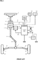
- a column shaft (a steering shaft or a handle shaft) 2 connected to a steering wheel 1 is connected to steered wheels 8L and 8R through reduction gears 3, universal joints 4a and 4b, a rack-and-pinion mechanism 5, and tie rods 6a and 6b, further via hub units 7a and 7b.
- the column shaft 2 is provided with a torque sensor 10 for detecting a steering torque of the steering wheel 1 and a steering angle sensor 14 for detecting a steering angle ⁇ , and a motor 20 for assisting a steering force of the steering wheel 1 is connected to the column shaft 2 through the reduction gears 3.
- the electric power is supplied to a control unit (ECU) 30 for controlling the electric power steering apparatus from a battery 13, and an ignition key (IG) signal is inputted into the control unit 30 through an ignition key 11.
- the control unit 30 calculates a current command value of an assist (steering assist) command on the basis of a steering torque Ts detected by the torque sensor 10 and a vehicle speed Vs detected by a vehicle speed sensor 12, and controls a current supplied to the motor 20 for the EPS by means of a voltage control command value Vref obtained by performing compensation or the like to the current command value.
- the steering angle sensor 14 is not essential, it does not need to be provided, and it is possible to obtain the steering angle from a rotation sensor such as a resolver connected to the motor 20.
- a controller area network (CAN) 100 exchanging various information of a vehicle is connected to the control unit 30, and it is possible to receive the vehicle speed Vs from the CAN 100. Further, it is also possible to connect a non-CAN 101 exchanging a communication, analog/digital signals, a radio wave or the like except with the CAN 100 to the control unit 30.
- CAN controller area network
- the control unit 30 mainly comprises an MCU (including a CPU, an MPU and so on), and general functions performed by programs within the MCU are shown in FIG. 2 .
- the steering torque Ts detected by the torque sensor 10 and the vehicle speed Vs detected by the vehicle speed sensor 12 are inputted into a current command value calculating section 31 that calculates a current command value Iref1.
- the current command value calculating section 31 calculates the current command value Iref1 that is a control target value of a motor current supplied to the motor 20 on the basis of the inputted steering torque Ts and the inputted vehicle speed Vs and by using an assist map or the like.
- the current command value Iref1 is inputted into a current limiting section 33 through an adding section 32A.
- the deviation I is inputted into a proportional-integral (PI) control section 35 for improving a characteristic of the steering operation.
- the voltage control command value Vref whose characteristic is improved by the PI-control section 35 is inputted into a PWM-control section 36.
- the motor 20 is PWM-driven through an inverter 37 serving as a driving section.
- the motor current value Im of the motor 20 is detected by a motor current detector 38 and is fed back to the subtracting section 32B.
- the inverter 37 uses field effect transistors (FETs) as driving elements and is comprised of a bridge circuit of FETs.
- a compensation signal CM from a compensation signal generating section 34 is added to the adding section 32A, and a characteristic compensation of the steering system is performed by the addition of the compensation signal CM so as to improve a convergence, an inertia characteristic and so on.
- the compensation signal generating section 34 adds a self-aligning torque (SAT) 34-3 and an inertia 34-2 at an adding section 34-4, further adds the result of addition performed at the adding section 34-4 with a convergence 34-1 at an adding section 34-5, and then outputs the result of addition performed at the adding section 34-5 as the compensation signal CM.
- SAT self-aligning torque
- a component and a peripheral object of the apparatus constitute resonance systems. Since resonances of the resonance systems generate a vibration, a noisy sound and so on, suppression of them is desired, and various measures have been proposed.
- Patent Document 1 a technique of eliminating a mechanical resonance frequency component of a rigid body part in a component of the electric power steering apparatus, such as a column and a rack, or a vehicle front structure.
- the technique in Patent Document 1 eliminates the mechanical resonance frequency component by using a band cut filter (a band stop filter) or a notch filter having a steep damping characteristic, and further combining a low pass filter of second or more order with it.
- control performed from input of the steering torque and the vehicle speed to output of the current command value Irefm and control (current control) performed from input of the current command value Irefm to output of the motor current value Im, are performed periodically in the control unit 30 of the electric power steering apparatus, and when a relationship between a period (an operation period) Ts_trq of the torque control and a period (an operation period) Ts_cur of the current control is Ts_trq ⁇ Ts_cur, an update period of the current command value in the current control is affected by an update period of the current command value in the torque control. For example, it is assumed that the current command values in the torque control and the current control are updated respectively as shown in FIGs. 3A and 3B .
- FIGs. 3A and 3B the horizontal axis shows time, the vertical axis shows the current command value, FIG. 3A shows a state of updating the current command value in the torque control, FIG. 3B shows a state of updating the current command value in the current control, and the operation period Ts_trq of the torque control is longer than the operation period Ts_cur of the current control.
- time points t 1 , t 2 and t 3 are timing to input the current command value from the torque control in order to perform new calculation in the current control, however, these time points are within one operation period of the torque control, and the current command value is not updated in the torque control, so that the current command value in the current control is not updated either.
- the current command value is updated at a time point t 4 being timing to perform new calculation in the torque control, and the current command value in the current control is also updated at a time point t 5 being timing to perform new calculation in the current control after the time point t 4 .
- the current command value is updated at a time point t 6 being timing to perform next new calculation in the torque control, and the current command value in the current control is updated at a time point t 7 being timing to perform new calculation in the current control after the time point t 6 .
- the current command value in the current control is not updated in the operation period Ts_cur of the current control, but is updated in the time between the time point t 5 and the time point t 7 , that is, the operation period Ts_trq of the torque control.
- FIG. 4 is a graph showing the above state, and indicates power spectra of the current command value in setting a frequency [Hz] to the horizontal axis and setting a power spectrum [dB] to the vertical axis.
- steep power spectra occur in the vicinity of frequencies which are natural number times of fs_trq/2. This is because fs_trq/2 is equivalent to the Nyquist frequency of the update period (equal to the operation period) of the current command value in the torque control, and with respect to the current command value in the current control, the power spectra become large at the frequencies which are natural number times of fs_trq/2.
- a resonance frequency band for example, from several Hz to several kHz of the mechanical resonance
- Patent Document 1 Since the technique in Patent Document 1 uses a filter having a steep damping characteristic in a narrow frequency band to eliminate the mechanical resonance frequency component, it cannot accurately suppress the vibration, the noisy sound and so on, whose frequency bands are different, whose vibration source is the power spectrum occurring from the relationship between the operation period of the torque control and the operation period of the current control, and which occur regardless of presence or absence of the mechanical resonance as described above.
- Patent Document 2 As an apparatus that eliminates a noise occurring depending on an operation, for example, an apparatus disclosed in the publication of Japanese Patent No. 5235536 B2 (Patent Document 2) uses a noise filter in order to eliminate a noise excited by a signal quantization error, a differential calculation or the like.
- the object of Patent Document 2 is to obtain a steering control apparatus where an operation amount is small and which is configured systematically and simply, and the apparatus in Patent Document 2 eliminates the noise by comprising a phase delay compensating section for setting a low frequency characteristic and a high range compensating section for setting a high frequency characteristic, and providing the noise filter in a post stage of them.
- the apparatus may become unstabilized by an influence of a phase delay in a control range.
- the present invention has been developed in view of the above-described circumstances, and an object of the present invention is to provide an electric power steering apparatus that can accurately suppress the vibration, the noisy sound and so on whose vibration source is the power spectrum occurring from the relationship between the operation period of the torque control and the operation period of the current control, and which occur regardless of presence or absence of the mechanical resonance.
- the present invention relates to an electric power steering apparatus that comprises a torque control section which calculates a current command value based on at least a steering torque and a current control section which controls a motor current flowing to a motor based on the current command value, the above-described object of the present invention is achieved by that wherein an operation period of the torque control section is longer than or equal to an operation period of the current control section; and wherein the current control section comprises a specific frequency band eliminating section that attenuates at least one frequency component having a frequency obtained by multiplying about half of an operation frequency of the torque control section by a natural number in the current command value.
- the specific frequency band eliminating section comprises a notch filter; or wherein the specific frequency band eliminating section comprises a plurality of notch filters connected in series; or wherein the specific frequency band eliminating section comprises a low pass filter connected to the notch filter in series; or wherein the specific frequency band eliminating section inputs the current command value outputted from the torque control section.
- the electric power steering apparatus of the present invention enables accurate suppression of a vibration, a noisy sound and so on whose vibration source is a power spectrum occurring from a relationship between the operation period of the torque control and the operation period of the current control, and which occur regardless of presence or absence of a mechanical resonance, by using the filter that attenuates a frequency component having a frequency obtained by multiplying half of the operation frequency of the torque control by a natural number.
- the present invention attenuates a frequency component of a steep power spectrum occurring from a relationship between an operation period Ts_trq of torque control and an operation period Ts_cur of current control by using a filter having a steep damping characteristic in a narrow band, such as a notch filter.
- the operation period Ts_trq of the torque control and the operation period Ts_cur of the current control can be made different, for example, because of difference of an operation amount in each control.
- the setting of Ts_trq ⁇ Ts_cur can be performed, and in this case, the power spectrum described above occurs.
- the notch filter is a filter of which a stopped frequency band is especially narrow among band stop filters.
- FIG. 5 shows a configuration example (a first embodiment) of an embodiment of the present invention corresponding to FIG. 2 , the same configurations are designated with the same numerals, and the explanation is omitted.
- a specific frequency band eliminating section 40 is provided between a current limiting section 33 and a subtracting section 32B.
- a torque control section 300 comprises a current command value calculating section 31, an adding section 32A, the current limiting section 33 and a compensation signal generating section 34, and a current control section 310 comprises the specific frequency band eliminating section 40, the subtracting section 32B, a PI-control section 35, a PWM-control section 36, an inverter 37 and a motor current detector 38.
- the torque control section 300 performs torque control in the operation period Ts_trq
- the current control section 310 performs current control in the operation period Ts_cur
- Ts_trq ⁇ Ts_cur is set.
- installation of the compensation signal generating section 34 is optional, and an addition, a change or the like of a compensation content is possible.
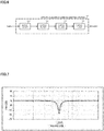
- the specific frequency band eliminating section 40 is configured by connecting four notch filters in series as shown in FIG. 6 .
- damping frequencies of notch filters 401, 402, 403 and 404 are set at fs_trq / 2, fs_trq, fs_trq ⁇ 3 / 2 and fs_trq ⁇ 2 respectively.
- the damping frequency indicates a frequency where an amplitude is the smallest in an amplitude characteristic of a filter, and can be called a notch frequency, a center frequency or the like.
- Each notch filter is designed as a secondary filter, and the frequency characteristic is shown by a transfer function G of the following expression 1 in the case of defining the damping frequency as "fe".
- G ⁇ d 2 ⁇ n 2 s 2 + 2 ⁇ n ⁇ n s + ⁇ n 2 s 2 + 2 ⁇ d ⁇ d s + ⁇ d 2
- "s" is a Laplace operator
- ⁇ n and ⁇ d are damping coefficients
- ⁇ n ⁇ ⁇ d the amplitude characteristic becomes, for example, a characteristic shown in FIG. 7 .
- FIG. 7 In FIG.
- the transfer function G is defined as an expression of a continuous system in the expression 1, it is used by being transformed into a secondary filter of a discrete system in implementation.
- Parameters of the expression 1 that are calculated and set in advance by setting fe fs_trq / 2, are held in the notch filter 401, and the notch filter 401 transforms an inputted current command value (a current command value signal) on the basis of the expression 1.
- notch filters 401, 402, 403 and 404 may be connected in an order other than the order shown in FIG. 6 .
- a sample-and-hold section which is not shown in FIG. 5 , exists between the current limiting section 33 of the torque control section 300 and the specific frequency band eliminating section 40 of the current control section 310. Since the operation period Ts_trq of the torque control section 300 and the operation period Ts_cur of the current control section 310 are different, the current control section 310 cannot receive the data (the current command value) outputted from the torque control section 300 in synchronization with the torque control section 300. Therefore, the sample-and-hold section stores (samples) the data outputted from the torque control section 300, and holds it until the current control section 310 can receive it. For example, in the case of updating the current command value as shown in the above FIG.
- the current control section 310 can receive its current command value at the time point t 5 , so that the sample-and-hold section holds its current command value until the time point t 5 when the current control section 310 can receive it.
- the sample-and-hold section holds the current command value updated at the time point t 6 until the time point t 7 when the current control section 310 can receive it. This enables avoidance of missing of the data.
- the sample-and-hold section may be included in the specific frequency band eliminating section 40.
- the notch filter 401 inputs the current command value Irefm, and transforms the current command value Irefm on the basis of the expression 1 by using the held parameter.
- the transformed current command value Irefm is inputted into the notch filters 402, 403 and 404 sequentially, and each notch filter transforms the current command value on the basis of the expression 1 by using the held parameter (Step S20).
- the current command value transformed by the notch filter 404 is outputted to the subtracting section 32B as a current command value Irefn1 (Step S30).
- a motor 20 is PWM-driven (Step S40), and a motor current value Im detected by the motor current detector 38 is fed back to the subtracting section 32B (Step S50).
- FIG. 9 A result of applying the present embodiment to the current command value having the power spectrum shown in FIG. 4 , is shown in FIG. 9 .
- FIG. 9 indicates the power spectra of the current command value in setting a frequency [Hz] to the horizontal axis and setting a power spectrum [dB] to the vertical axis. Comparing the power spectra shown in FIG. 4 and the power spectra shown in FIG. 9 , it is found out that the steep power spectrum (circled by the broken line) occurring every half frequency of the operation frequency fs_trq is reduced.
- LPF an LPF whose cutoff frequency is 300 Hz so that the amplitude at 500 Hz coincides with the amplitude of the notch filter, is used. Amplitude characteristics of the notch filter and the LPF are shown in FIG. 10A , and phase characteristics of them are shown in FIG. 10B . In FIGs.
- the horizontal axis shows a frequency [Hz]
- the vertical axis in FIG. 10A shows an amplitude (a gain) [dB]
- the vertical axis in FIG. 10B shows a phase [deg]
- the thick line shows the frequency characteristic of the notch filter
- the thin line shows the frequency characteristic of the LPF.
- a difference (a phase change amount) between the phase characteristic of the notch filter and the phase characteristic of the LPF is shown in FIG. 11 .
- the horizontal axis shows a frequency [Hz]
- FIGs. 13A and 13B a simulation result of a time response of a steering torque (a torsion bar torque) is shown in FIGs. 13A and 13B in the case of changing a steering wheel angle (an angle on an upper side of a torsion bar) as shown in FIG. 12 .
- the horizontal axis shows time [sec]
- the vertical axis shows the steering torque [newton meter (Nm)]
- the thick line shows the time response in the case of using the notch filter
- the thin line shows the time response in the case of using the LPF.
- FIG. 13B shows the time response by enlarging the time response in the time range (6 to 6.5 sec) shown by "X" in FIG. 13A .
- a vibration of the steering torque is reduced in the case of using the notch filter more than in the case of using the LPF. This is because a phase delay is recovered in the case of using the notch filter more than in the case of using the LPF as shown in FIG. 11 (for example, it is recovered about 9 deg at 50 Hz), and the vibration is reduced by its influence.
- using the notch filter enables improvement of stability of a system and improvement of a vibration occurring by an influence of a feedback loop.
- the first embodiment comprises four notch filters
- the specific frequency band eliminating section 40 can comprise only the notch filter 401.
- the notch filter whose damping frequency is this frequency can be added to the specific frequency band eliminating section 40.
- the damping frequency of the notch filter may be set at a value obtained by adding some tolerance (for example, within ⁇ 5 %) to a desired frequency (n/2 times of fs_trq ("n" is a natural number)).
- the specific frequency band eliminating section 40 comprises the notch filter, it may comprise a band stop filter other than the notch filter.
- the specific frequency band eliminating section 40 may comprises the notch filter and the other band stop filter mixedly.
- the stopband of the notch filter is narrower than ones of other band stop filters, a configuration where the notch filter is used for a range where a frequency component of a narrow band is desired to attenuate and a band stop filter other than the notch filter is used for a range where a frequency component of a band having some tolerance is desired to attenuate, etc., can be adopted.
- a specific frequency band eliminating section comprises a notch filter and a low pass filter.
- FIG. 14 shows a configuration example of a specific frequency band eliminating section 41 in the present embodiment. Compared with the specific frequency band eliminating section 40 in the first embodiment shown in FIG. 6 , a low pass filter 411 is provided instead of the notch filters 403 and 404. Other configurations are the same as the first embodiment.
- the notch filters 401 and 402 whose damping frequencies are fs_trq / 2 and fs_trq respectively, are designed so as to attenuate the frequency components of these frequencies respectively, so that the low pass filter 411 is designed so as to reduce a frequency component of a frequency more than or equal to fs_trq ⁇ 3 / 2.
- the frequency characteristic is shown by a transfer function G 1 of the following expression 2.
- G 1 1 s ⁇ c + 1
- ⁇ c 2 ⁇ ⁇ fc
- fc is a cutoff frequency
- the low pass filter 411 is designed so as to set fc ⁇ fs_trq ⁇ 3 / 2.
- a transfer function G 2 is defined by the following expression 3.
- G 2 1 s ⁇ c 2 + 2 ⁇ s ⁇ c + 1
- ⁇ is a damping coefficient
- ⁇ c 2 ⁇ ⁇ fc
- the low pass filter 411 is designed so as to set fc ⁇ fs_trq ⁇ 3 / 2.
- a preset parameter of the expression 2 or the expression 3 is held in the low pass filter 411, and the low pass filter 411 transforms the inputted current command value on the basis of the expression 2 or the expression 3.
- the notch filters 401 and 402, and the low pass filter 411 may be connected in an order other than the order shown in FIG. 14 .
- An operation of the second embodiment is the same as the operation of the first embodiment.
- the current command value Irefm inputted into the specific frequency band eliminating section 41 is sequentially transformed by the notch filters 401 and 402, and the low pass filter 411, and the transformed current command value is outputted to the subtracting section 32B as a current command value Irefn2.
- the low pass filter reduces the frequency components of power spectra in frequencies more than or equal to a fixed frequency (fs_trq ⁇ 3 / 2 in the second embodiment) among the steep power spectra occurring every half frequency of the operation frequency fs_trq, so that it is possible to reduce the frequency components of the above power spectra with a smaller operation amount than in the case of using the notch filter.
- the second embodiment comprises two notch filters, it may comprises one notch filter, or three or more notch filters.
- the cutoff frequency of the low pass filter is set so that the low pass filter reduces frequency components other than the frequency component reduced by the notch filter.
- the order of the transfer function of the low pass filter may be more than or equal to three.
- a band stop filter other than the notch filter may be used instead of the notch filter.
- FIG. 15 shows a configuration example of the present embodiment corresponding to FIG. 2 and FIG. 5 , the same configurations are designated with the same numerals, and the explanation is omitted.
- a specific frequency band eliminating section 42 is provided between the subtracting section 32B and the PI-control section 35 in the third embodiment. Therefore, not the current command value Irefm but a deviation I between the current command value Irefm and the motor current value Im, is inputted into the specific frequency band eliminating section 42.
- the specific frequency band eliminating section 42 exhibits the same effect as the first embodiment or the second embodiment by being configured in the same configuration as the specific frequency band eliminating section 40 of the first embodiment or the specific frequency band eliminating section 41 of the second embodiment, and performing the same operation as it.
- the above embodiments (the first embodiment to the third embodiment) comprise one specific frequency band eliminating section
- two specific frequency band eliminating sections may be provided at the position of the first embodiment and the second embodiment (between the current limiting section 33 and the subtracting section 32B) and at the position of the third embodiment (between the subtracting section 32B and the PI-control section 35) respectively.
- the notch filters and the low pass filter constituting the specific frequency band eliminating section are divided, and are allocated to respective specific frequency band eliminating sections provided at the two positions.
Landscapes
- Engineering & Computer Science (AREA)
- Chemical & Material Sciences (AREA)
- Combustion & Propulsion (AREA)
- Transportation (AREA)
- Mechanical Engineering (AREA)
- Steering Control In Accordance With Driving Conditions (AREA)
- Power Steering Mechanism (AREA)
- Control Of Electric Motors In General (AREA)
- Control Of Ac Motors In General (AREA)
Applications Claiming Priority (3)
| Application Number | Priority Date | Filing Date | Title |
|---|---|---|---|
| JP2015161698 | 2015-08-19 | ||
| JP2016037404 | 2016-02-29 | ||
| PCT/JP2016/073563 WO2017030067A1 (fr) | 2015-08-19 | 2016-08-10 | Dispositif de direction assistée électrique |
Publications (3)
| Publication Number | Publication Date |
|---|---|
| EP3257728A1 true EP3257728A1 (fr) | 2017-12-20 |
| EP3257728A4 EP3257728A4 (fr) | 2018-05-02 |
| EP3257728B1 EP3257728B1 (fr) | 2019-03-06 |
Family
ID=58051721
Family Applications (1)
| Application Number | Title | Priority Date | Filing Date |
|---|---|---|---|
| EP16837057.5A Not-in-force EP3257728B1 (fr) | 2015-08-19 | 2016-08-10 | Dispositif de direction assistée électrique |
Country Status (5)
| Country | Link |
|---|---|
| US (1) | US10173717B2 (fr) |
| EP (1) | EP3257728B1 (fr) |
| JP (1) | JP6222411B2 (fr) |
| CN (1) | CN107949517B (fr) |
| WO (1) | WO2017030067A1 (fr) |
Cited By (2)
| Publication number | Priority date | Publication date | Assignee | Title |
|---|---|---|---|---|
| EP3315387A4 (fr) * | 2016-05-12 | 2018-12-12 | NSK Ltd. | Appareil de direction à assistance électrique |
| EP4423467A4 (fr) * | 2021-10-29 | 2025-12-24 | Atieva Inc | Atténuation d'ordre vibratoire dans un moteur électrique |
Families Citing this family (5)
| Publication number | Priority date | Publication date | Assignee | Title |
|---|---|---|---|---|
| EP3434559A4 (fr) * | 2016-09-16 | 2019-11-20 | NSK Ltd. | Dispositif de direction assistée électrique |
| KR101950259B1 (ko) * | 2017-05-22 | 2019-02-22 | 주식회사 만도 | 전동식 조향장치의 조향정보 검출 장치 및 조향정보 검출방법 |
| JP7156131B2 (ja) * | 2019-03-27 | 2022-10-19 | オムロン株式会社 | サーボdc給電システム及びモータ制御装置 |
| JP7491785B2 (ja) * | 2020-09-07 | 2024-05-28 | 株式会社ジェイテクト | 操舵制御装置 |
| US12172706B2 (en) * | 2021-09-29 | 2024-12-24 | Nidec Corporation | Motor control device, motor control method, motor module, and electric power steering device |
Family Cites Families (15)
| Publication number | Priority date | Publication date | Assignee | Title |
|---|---|---|---|---|
| US6107767A (en) * | 1998-03-20 | 2000-08-22 | Trw Inc. | Electric assist steering system having an improved motor current controller with notch filter |
| JPH11286280A (ja) | 1998-04-03 | 1999-10-19 | Mitsubishi Electric Corp | 車両の自動走行制御装置 |
| WO2001047762A1 (fr) * | 1999-12-29 | 2001-07-05 | Delphi Technologies, Inc. | Procede et systeme d'amelioration de la stabilite d'un vehicule moteur incorporant un systeme de direction assistee electrique |
| JP4057955B2 (ja) | 2003-05-28 | 2008-03-05 | 本田技研工業株式会社 | 車両の自動操舵装置 |
| EP1837266B1 (fr) * | 2005-01-14 | 2012-03-14 | Nsk Ltd. | Controleur de dispositif de direction a assistance electrique |
| JP4676254B2 (ja) * | 2005-05-31 | 2011-04-27 | 日立ビアメカニクス株式会社 | ディジタルサーボ制御装置及びレーザ加工装置 |
| JP5040420B2 (ja) * | 2007-05-07 | 2012-10-03 | 株式会社ジェイテクト | 電動パワーステアリング装置 |
| JP5235536B2 (ja) | 2008-07-03 | 2013-07-10 | 三菱電機株式会社 | 電動パワーステアリング制御装置 |
| US8271163B2 (en) * | 2009-09-23 | 2012-09-18 | GM Global Technology Operations LLC | Method for attenuating smooth road shake in an electric power steering system |
| JP5456576B2 (ja) | 2010-05-24 | 2014-04-02 | 三菱電機株式会社 | 電動パワーステアリング装置 |
| US9254862B2 (en) * | 2011-05-25 | 2016-02-09 | Mitsubishi Electric Corporation | Electric power steering control device |
| JP6030459B2 (ja) * | 2013-01-24 | 2016-11-24 | トヨタ自動車株式会社 | 車両の操舵制御装置 |
| CN105083370B (zh) * | 2014-05-09 | 2018-01-16 | 现代摩比斯株式会社 | Mdps的补偿控制装置 |
| KR102389093B1 (ko) * | 2015-12-10 | 2022-04-21 | 주식회사 만도 | 조향 제어 장치 및 조향 제어 방법 |
| WO2017213130A1 (fr) * | 2016-06-06 | 2017-12-14 | 日本精工株式会社 | Dispositif de direction assistée électrique |
-
2016
- 2016-08-10 WO PCT/JP2016/073563 patent/WO2017030067A1/fr not_active Ceased
- 2016-08-10 US US15/559,118 patent/US10173717B2/en not_active Expired - Fee Related
- 2016-08-10 CN CN201680048571.XA patent/CN107949517B/zh not_active Expired - Fee Related
- 2016-08-10 JP JP2017534625A patent/JP6222411B2/ja not_active Expired - Fee Related
- 2016-08-10 EP EP16837057.5A patent/EP3257728B1/fr not_active Not-in-force
Cited By (4)
| Publication number | Priority date | Publication date | Assignee | Title |
|---|---|---|---|---|
| EP3315387A4 (fr) * | 2016-05-12 | 2018-12-12 | NSK Ltd. | Appareil de direction à assistance électrique |
| CN109153409A (zh) * | 2016-05-12 | 2019-01-04 | 日本精工株式会社 | 电动助力转向装置 |
| EP4423467A4 (fr) * | 2021-10-29 | 2025-12-24 | Atieva Inc | Atténuation d'ordre vibratoire dans un moteur électrique |
| US12558968B2 (en) | 2021-10-29 | 2026-02-24 | Atieva, Inc. | Vibrational order attenuation in an electric motor |
Also Published As
| Publication number | Publication date |
|---|---|
| CN107949517A (zh) | 2018-04-20 |
| JPWO2017030067A1 (ja) | 2017-11-09 |
| WO2017030067A1 (fr) | 2017-02-23 |
| CN107949517B (zh) | 2019-03-26 |
| US10173717B2 (en) | 2019-01-08 |
| EP3257728A4 (fr) | 2018-05-02 |
| EP3257728B1 (fr) | 2019-03-06 |
| JP6222411B2 (ja) | 2017-11-01 |
| US20180244307A1 (en) | 2018-08-30 |
Similar Documents
| Publication | Publication Date | Title |
|---|---|---|
| EP3257728B1 (fr) | Dispositif de direction assistée électrique | |
| US10046790B2 (en) | Electric power steering apparatus | |
| EP2990302B1 (fr) | Dispositif de direction à assistance électrique | |
| US10526009B2 (en) | Electric power steering apparatus | |
| US9796413B2 (en) | Electric power steering apparatus | |
| US10099721B2 (en) | Electric power steering apparatus | |
| US20200172162A1 (en) | Electric power steering apparatus | |
| EP3489114A1 (fr) | Appareil de direction à assistance électrique | |
| US20220135117A1 (en) | Control apparatus of steering system for vehicles | |
| EP3284648B1 (fr) | Dispositif de commande pour dispositif de direction assistée électrique | |
| JP6022117B2 (ja) | 電動パワーステアリング装置 | |
| JPWO2018147371A1 (ja) | 電動パワーステアリング装置 | |
| EP3199426A1 (fr) | Dispositif de direction assistée électrique | |
| EP3282576B1 (fr) | Dispositif de commande de moteur et dispositif de direction assistée électrique le comportant | |
| EP2402234B1 (fr) | Compensateur de système dynamique pour systèmes de direction assistée contrôlés activement | |
| EP1863163A1 (fr) | Contrôleur de moteur | |
| JP2019188896A (ja) | ステアリング制御装置 |
Legal Events
| Date | Code | Title | Description |
|---|---|---|---|
| STAA | Information on the status of an ep patent application or granted ep patent |
Free format text: STATUS: THE INTERNATIONAL PUBLICATION HAS BEEN MADE |
|
| PUAI | Public reference made under article 153(3) epc to a published international application that has entered the european phase |
Free format text: ORIGINAL CODE: 0009012 |
|
| STAA | Information on the status of an ep patent application or granted ep patent |
Free format text: STATUS: REQUEST FOR EXAMINATION WAS MADE |
|
| 17P | Request for examination filed |
Effective date: 20170913 |
|
| AK | Designated contracting states |
Kind code of ref document: A1 Designated state(s): AL AT BE BG CH CY CZ DE DK EE ES FI FR GB GR HR HU IE IS IT LI LT LU LV MC MK MT NL NO PL PT RO RS SE SI SK SM TR |
|
| AX | Request for extension of the european patent |
Extension state: BA ME |
|
| REG | Reference to a national code |
Ref country code: DE Ref legal event code: R079 Ref document number: 602016010830 Country of ref document: DE Free format text: PREVIOUS MAIN CLASS: B62D0006000000 Ipc: B62D0005040000 |
|
| A4 | Supplementary search report drawn up and despatched |
Effective date: 20180406 |
|
| RIC1 | Information provided on ipc code assigned before grant |
Ipc: B62D 119/00 20060101ALI20180329BHEP Ipc: B62D 5/04 20060101AFI20180329BHEP Ipc: B62D 6/00 20060101ALI20180329BHEP |
|
| GRAP | Despatch of communication of intention to grant a patent |
Free format text: ORIGINAL CODE: EPIDOSNIGR1 |
|
| STAA | Information on the status of an ep patent application or granted ep patent |
Free format text: STATUS: GRANT OF PATENT IS INTENDED |
|
| DAV | Request for validation of the european patent (deleted) | ||
| DAX | Request for extension of the european patent (deleted) | ||
| INTG | Intention to grant announced |
Effective date: 20181024 |
|
| GRAS | Grant fee paid |
Free format text: ORIGINAL CODE: EPIDOSNIGR3 |
|
| GRAA | (expected) grant |
Free format text: ORIGINAL CODE: 0009210 |
|
| STAA | Information on the status of an ep patent application or granted ep patent |
Free format text: STATUS: THE PATENT HAS BEEN GRANTED |
|
| AK | Designated contracting states |
Kind code of ref document: B1 Designated state(s): AL AT BE BG CH CY CZ DE DK EE ES FI FR GB GR HR HU IE IS IT LI LT LU LV MC MK MT NL NO PL PT RO RS SE SI SK SM TR |
|
| REG | Reference to a national code |
Ref country code: GB Ref legal event code: FG4D |
|
| REG | Reference to a national code |
Ref country code: CH Ref legal event code: EP Ref country code: AT Ref legal event code: REF Ref document number: 1104147 Country of ref document: AT Kind code of ref document: T Effective date: 20190315 |
|
| REG | Reference to a national code |
Ref country code: DE Ref legal event code: R096 Ref document number: 602016010830 Country of ref document: DE |
|
| REG | Reference to a national code |
Ref country code: IE Ref legal event code: FG4D |
|
| REG | Reference to a national code |
Ref country code: NL Ref legal event code: MP Effective date: 20190306 |
|
| REG | Reference to a national code |
Ref country code: LT Ref legal event code: MG4D |
|
| PG25 | Lapsed in a contracting state [announced via postgrant information from national office to epo] |
Ref country code: SE Free format text: LAPSE BECAUSE OF FAILURE TO SUBMIT A TRANSLATION OF THE DESCRIPTION OR TO PAY THE FEE WITHIN THE PRESCRIBED TIME-LIMIT Effective date: 20190306 Ref country code: LT Free format text: LAPSE BECAUSE OF FAILURE TO SUBMIT A TRANSLATION OF THE DESCRIPTION OR TO PAY THE FEE WITHIN THE PRESCRIBED TIME-LIMIT Effective date: 20190306 Ref country code: NO Free format text: LAPSE BECAUSE OF FAILURE TO SUBMIT A TRANSLATION OF THE DESCRIPTION OR TO PAY THE FEE WITHIN THE PRESCRIBED TIME-LIMIT Effective date: 20190606 Ref country code: FI Free format text: LAPSE BECAUSE OF FAILURE TO SUBMIT A TRANSLATION OF THE DESCRIPTION OR TO PAY THE FEE WITHIN THE PRESCRIBED TIME-LIMIT Effective date: 20190306 |
|
| PG25 | Lapsed in a contracting state [announced via postgrant information from national office to epo] |
Ref country code: BG Free format text: LAPSE BECAUSE OF FAILURE TO SUBMIT A TRANSLATION OF THE DESCRIPTION OR TO PAY THE FEE WITHIN THE PRESCRIBED TIME-LIMIT Effective date: 20190606 Ref country code: HR Free format text: LAPSE BECAUSE OF FAILURE TO SUBMIT A TRANSLATION OF THE DESCRIPTION OR TO PAY THE FEE WITHIN THE PRESCRIBED TIME-LIMIT Effective date: 20190306 Ref country code: RS Free format text: LAPSE BECAUSE OF FAILURE TO SUBMIT A TRANSLATION OF THE DESCRIPTION OR TO PAY THE FEE WITHIN THE PRESCRIBED TIME-LIMIT Effective date: 20190306 Ref country code: NL Free format text: LAPSE BECAUSE OF FAILURE TO SUBMIT A TRANSLATION OF THE DESCRIPTION OR TO PAY THE FEE WITHIN THE PRESCRIBED TIME-LIMIT Effective date: 20190306 Ref country code: LV Free format text: LAPSE BECAUSE OF FAILURE TO SUBMIT A TRANSLATION OF THE DESCRIPTION OR TO PAY THE FEE WITHIN THE PRESCRIBED TIME-LIMIT Effective date: 20190306 Ref country code: GR Free format text: LAPSE BECAUSE OF FAILURE TO SUBMIT A TRANSLATION OF THE DESCRIPTION OR TO PAY THE FEE WITHIN THE PRESCRIBED TIME-LIMIT Effective date: 20190607 |
|
| REG | Reference to a national code |
Ref country code: AT Ref legal event code: MK05 Ref document number: 1104147 Country of ref document: AT Kind code of ref document: T Effective date: 20190306 |
|
| PG25 | Lapsed in a contracting state [announced via postgrant information from national office to epo] |
Ref country code: AL Free format text: LAPSE BECAUSE OF FAILURE TO SUBMIT A TRANSLATION OF THE DESCRIPTION OR TO PAY THE FEE WITHIN THE PRESCRIBED TIME-LIMIT Effective date: 20190306 Ref country code: PT Free format text: LAPSE BECAUSE OF FAILURE TO SUBMIT A TRANSLATION OF THE DESCRIPTION OR TO PAY THE FEE WITHIN THE PRESCRIBED TIME-LIMIT Effective date: 20190706 Ref country code: IT Free format text: LAPSE BECAUSE OF FAILURE TO SUBMIT A TRANSLATION OF THE DESCRIPTION OR TO PAY THE FEE WITHIN THE PRESCRIBED TIME-LIMIT Effective date: 20190306 Ref country code: SK Free format text: LAPSE BECAUSE OF FAILURE TO SUBMIT A TRANSLATION OF THE DESCRIPTION OR TO PAY THE FEE WITHIN THE PRESCRIBED TIME-LIMIT Effective date: 20190306 Ref country code: EE Free format text: LAPSE BECAUSE OF FAILURE TO SUBMIT A TRANSLATION OF THE DESCRIPTION OR TO PAY THE FEE WITHIN THE PRESCRIBED TIME-LIMIT Effective date: 20190306 Ref country code: RO Free format text: LAPSE BECAUSE OF FAILURE TO SUBMIT A TRANSLATION OF THE DESCRIPTION OR TO PAY THE FEE WITHIN THE PRESCRIBED TIME-LIMIT Effective date: 20190306 Ref country code: ES Free format text: LAPSE BECAUSE OF FAILURE TO SUBMIT A TRANSLATION OF THE DESCRIPTION OR TO PAY THE FEE WITHIN THE PRESCRIBED TIME-LIMIT Effective date: 20190306 Ref country code: CZ Free format text: LAPSE BECAUSE OF FAILURE TO SUBMIT A TRANSLATION OF THE DESCRIPTION OR TO PAY THE FEE WITHIN THE PRESCRIBED TIME-LIMIT Effective date: 20190306 |
|
| PGFP | Annual fee paid to national office [announced via postgrant information from national office to epo] |
Ref country code: DE Payment date: 20190730 Year of fee payment: 4 Ref country code: FR Payment date: 20190711 Year of fee payment: 4 |
|
| PG25 | Lapsed in a contracting state [announced via postgrant information from national office to epo] |
Ref country code: SM Free format text: LAPSE BECAUSE OF FAILURE TO SUBMIT A TRANSLATION OF THE DESCRIPTION OR TO PAY THE FEE WITHIN THE PRESCRIBED TIME-LIMIT Effective date: 20190306 Ref country code: PL Free format text: LAPSE BECAUSE OF FAILURE TO SUBMIT A TRANSLATION OF THE DESCRIPTION OR TO PAY THE FEE WITHIN THE PRESCRIBED TIME-LIMIT Effective date: 20190306 |
|
| REG | Reference to a national code |
Ref country code: DE Ref legal event code: R097 Ref document number: 602016010830 Country of ref document: DE |
|
| PG25 | Lapsed in a contracting state [announced via postgrant information from national office to epo] |
Ref country code: IS Free format text: LAPSE BECAUSE OF FAILURE TO SUBMIT A TRANSLATION OF THE DESCRIPTION OR TO PAY THE FEE WITHIN THE PRESCRIBED TIME-LIMIT Effective date: 20190706 Ref country code: AT Free format text: LAPSE BECAUSE OF FAILURE TO SUBMIT A TRANSLATION OF THE DESCRIPTION OR TO PAY THE FEE WITHIN THE PRESCRIBED TIME-LIMIT Effective date: 20190306 |
|
| PLBE | No opposition filed within time limit |
Free format text: ORIGINAL CODE: 0009261 |
|
| STAA | Information on the status of an ep patent application or granted ep patent |
Free format text: STATUS: NO OPPOSITION FILED WITHIN TIME LIMIT |
|
| PG25 | Lapsed in a contracting state [announced via postgrant information from national office to epo] |
Ref country code: DK Free format text: LAPSE BECAUSE OF FAILURE TO SUBMIT A TRANSLATION OF THE DESCRIPTION OR TO PAY THE FEE WITHIN THE PRESCRIBED TIME-LIMIT Effective date: 20190306 |
|
| 26N | No opposition filed |
Effective date: 20191209 |
|
| PG25 | Lapsed in a contracting state [announced via postgrant information from national office to epo] |
Ref country code: SI Free format text: LAPSE BECAUSE OF FAILURE TO SUBMIT A TRANSLATION OF THE DESCRIPTION OR TO PAY THE FEE WITHIN THE PRESCRIBED TIME-LIMIT Effective date: 20190306 |
|
| PG25 | Lapsed in a contracting state [announced via postgrant information from national office to epo] |
Ref country code: TR Free format text: LAPSE BECAUSE OF FAILURE TO SUBMIT A TRANSLATION OF THE DESCRIPTION OR TO PAY THE FEE WITHIN THE PRESCRIBED TIME-LIMIT Effective date: 20190306 |
|
| PG25 | Lapsed in a contracting state [announced via postgrant information from national office to epo] |
Ref country code: MC Free format text: LAPSE BECAUSE OF FAILURE TO SUBMIT A TRANSLATION OF THE DESCRIPTION OR TO PAY THE FEE WITHIN THE PRESCRIBED TIME-LIMIT Effective date: 20190306 Ref country code: LU Free format text: LAPSE BECAUSE OF NON-PAYMENT OF DUE FEES Effective date: 20190810 Ref country code: LI Free format text: LAPSE BECAUSE OF NON-PAYMENT OF DUE FEES Effective date: 20190831 Ref country code: CH Free format text: LAPSE BECAUSE OF NON-PAYMENT OF DUE FEES Effective date: 20190831 |
|
| REG | Reference to a national code |
Ref country code: BE Ref legal event code: MM Effective date: 20190831 |
|
| PG25 | Lapsed in a contracting state [announced via postgrant information from national office to epo] |
Ref country code: IE Free format text: LAPSE BECAUSE OF NON-PAYMENT OF DUE FEES Effective date: 20190810 |
|
| PG25 | Lapsed in a contracting state [announced via postgrant information from national office to epo] |
Ref country code: BE Free format text: LAPSE BECAUSE OF NON-PAYMENT OF DUE FEES Effective date: 20190831 |
|
| REG | Reference to a national code |
Ref country code: DE Ref legal event code: R119 Ref document number: 602016010830 Country of ref document: DE |
|
| GBPC | Gb: european patent ceased through non-payment of renewal fee |
Effective date: 20200810 |
|
| PG25 | Lapsed in a contracting state [announced via postgrant information from national office to epo] |
Ref country code: CY Free format text: LAPSE BECAUSE OF FAILURE TO SUBMIT A TRANSLATION OF THE DESCRIPTION OR TO PAY THE FEE WITHIN THE PRESCRIBED TIME-LIMIT Effective date: 20190306 |
|
| PG25 | Lapsed in a contracting state [announced via postgrant information from national office to epo] |
Ref country code: FR Free format text: LAPSE BECAUSE OF NON-PAYMENT OF DUE FEES Effective date: 20200831 Ref country code: DE Free format text: LAPSE BECAUSE OF NON-PAYMENT OF DUE FEES Effective date: 20210302 Ref country code: MT Free format text: LAPSE BECAUSE OF FAILURE TO SUBMIT A TRANSLATION OF THE DESCRIPTION OR TO PAY THE FEE WITHIN THE PRESCRIBED TIME-LIMIT Effective date: 20190306 Ref country code: HU Free format text: LAPSE BECAUSE OF FAILURE TO SUBMIT A TRANSLATION OF THE DESCRIPTION OR TO PAY THE FEE WITHIN THE PRESCRIBED TIME-LIMIT; INVALID AB INITIO Effective date: 20160810 |
|
| PG25 | Lapsed in a contracting state [announced via postgrant information from national office to epo] |
Ref country code: GB Free format text: LAPSE BECAUSE OF NON-PAYMENT OF DUE FEES Effective date: 20200810 |
|
| PG25 | Lapsed in a contracting state [announced via postgrant information from national office to epo] |
Ref country code: MK Free format text: LAPSE BECAUSE OF FAILURE TO SUBMIT A TRANSLATION OF THE DESCRIPTION OR TO PAY THE FEE WITHIN THE PRESCRIBED TIME-LIMIT Effective date: 20190306 |