EP3258015B1 - Machine de compactage de sol et procédé de fabrication d'un poids de lestage pour une machine de compactage de sol - Google Patents
Machine de compactage de sol et procédé de fabrication d'un poids de lestage pour une machine de compactage de sol Download PDFInfo
- Publication number
- EP3258015B1 EP3258015B1 EP17169222.1A EP17169222A EP3258015B1 EP 3258015 B1 EP3258015 B1 EP 3258015B1 EP 17169222 A EP17169222 A EP 17169222A EP 3258015 B1 EP3258015 B1 EP 3258015B1
- Authority
- EP
- European Patent Office
- Prior art keywords
- enclosure
- impact
- concrete core
- filling material
- machine frame
- Prior art date
- Legal status (The legal status is an assumption and is not a legal conclusion. Google has not performed a legal analysis and makes no representation as to the accuracy of the status listed.)
- Active
Links
Images


Classifications
-
- E—FIXED CONSTRUCTIONS
- E02—HYDRAULIC ENGINEERING; FOUNDATIONS; SOIL SHIFTING
- E02D—FOUNDATIONS; EXCAVATIONS; EMBANKMENTS; UNDERGROUND OR UNDERWATER STRUCTURES
- E02D3/00—Improving or preserving soil or rock, e.g. preserving permafrost soil
- E02D3/02—Improving by compacting
- E02D3/026—Improving by compacting by rolling with rollers usable only for or specially adapted for soil compaction, e.g. sheepsfoot rollers
-
- E—FIXED CONSTRUCTIONS
- E01—CONSTRUCTION OF ROADS, RAILWAYS, OR BRIDGES
- E01C—CONSTRUCTION OF, OR SURFACES FOR, ROADS, SPORTS GROUNDS, OR THE LIKE; MACHINES OR AUXILIARY TOOLS FOR CONSTRUCTION OR REPAIR
- E01C19/00—Machines, tools or auxiliary devices for preparing or distributing paving materials, for working the placed materials, or for forming, consolidating, or finishing the paving
- E01C19/22—Machines, tools or auxiliary devices for preparing or distributing paving materials, for working the placed materials, or for forming, consolidating, or finishing the paving for consolidating or finishing laid-down unset materials
- E01C19/23—Rollers therefor; Such rollers usable also for compacting soil
- E01C19/29—Rolling apparatus adapted to apply a rolling pressure less than its weight, e.g. roller finishers travelling on formrail combined with spread-out, strike-off or smoothing means; Rolling elements with controlled penetration or a controlled path of movement in a vertical plane, e.g. controlled by the formrails, by guides ensuring a desired configuration of the rolled surface
Definitions
- the invention relates to a soil compacting machine, in particular a compactor according to the preamble of claim 1, as well as a method for producing a weight for a soil compacting machine according to the preamble of claim 9.
- Such soil compacting machines are, for example, single drum rollers, as they are known in particular from the machine program of the company Hamm AG, Tirschenreuth.
- a known generic compactor has a wheel axle with wheels mounted in the machine frame, as well as at least one drum mounted in a front vehicle.
- the front end is connected to the machine frame via an articulated steering system.
- the machine frame also carries a body with a driver's cab and a hood.
- a weight weight adapted to the body is attached to the machine frame.
- This weight is a molded part made of concrete that can be painted to match the look of the body.
- the drum of such a roller train can also be a crusher drum with which a wide variety of building materials and minerals can be crushed and compacted at the same time.
- a bandage can be used as a rock breaker or for pre-breaking and relaxing of rocky ground and also as a padfoot roller.
- ballast system for soil compaction machines with two wheel axles which has modular ballast elements for adaptation to different compaction tasks, the number and arrangement of which can be selected selectively.
- the ballast elements consist of ballast boxes that are filled, for example, with bulk material, for example wet sand.
- the aim of this prior art is to use a modular ballast system to attach different weights to the machine frame in order to enable the static compaction load to be adapted to the compaction work to be performed.
- the generic single drum rollers mentioned at the beginning do not require such a variation in the weight load.
- the weights cast from concrete can, however, be easily damaged because the concrete is only slightly pressure-resistant, and larger pieces of concrete can break off and require repair and / or cleaning of the damaged floor surface, so that work interruptions until a replacement can be obtained. Soil compaction machine can occur. Because of the risk of the weight losing further fragments, the component has to be replaced, so that significant business interruptions can occur, especially if a spare part is not immediately available.
- the invention is therefore based on the object of specifying a soil compacting machine or a method for producing a weight for a soil compacting machine with which operational interruptions even in the event of damage to the weight while working on a soil surface the soil compacting machine and work interruptions at a construction site can be avoided.
- the invention provides in an advantageous manner that the at least one weighting weight at least partially has an impact-resistant casing which forms part of the body.
- the casing is filled with filler material, so that the impact-resistant casing protects the filler material from impact loads, even if it is not sufficiently pressure-resistant. Even in the event that a non-pressure-resistant filling material is damaged or broken, it is ensured that the weight is still fully functional due to the almost complete coating, so that no noteworthy operational or work interruptions can take place.
- the impact-resistant casing is therefore preferably made of a material with a high impact strength, which protects the weight and keeps it functional even in the event of a violent collision.
- the weight can be almost completely surrounded by the casing.
- the weighting weight is preferably attached to the rear end of the machine frame as a body part.
- the impact-resistant casing is filled with a weighting filler material, which preferably has a concrete core.
- the sheathing thus forms an impact-resistant outer skin for the concrete core and gives the entire weight the necessary pressure resistance and impact resistance.
- the anchoring of the fastening means in the concrete core has the advantage that the fastening of the weight is overall more stable on the machine frame and can absorb higher impact forces and shear loads.
- the concrete core has reinforcement structures.
- Such reinforcement structures can be two or three dimensional structures of a material with high tensile strength, e.g. Be metal that are introduced during the manufacture of the concrete core.
- the reinforcement structures can have three-dimensional lattice structures, for example.
- the casing has walls with inwardly protruding anchors which are connected to the concrete core.
- the anchorages can be connected to the concrete core or to the reinforcement structures contained therein, for example via wire brackets.
- the anchoring of the walls can extend into the concrete core. It goes without saying that the anchorages can also be in one piece with the walls of the casing.
- the impact-resistant casing has walls made of plastic material. Plastics with high tensile strengths and high impact strength values are preferred.
- the walls of the sheathing can have an incorporated reinforcement structure, wherein the walls can have a fiber-reinforced plastic, at least in some areas, or can be formed from fiber-reinforced plastic.
- the casing with walls made of plastic material can be painted and can also be formed from plastics that are multilayered and in particular already contain an outer layer of paint, so that subsequent painting can be dispensed with.
- the attachment means of the weight can be attached to the reinforcement structures of the concrete core.
- the weighting weight is formed from an impact-resistant casing which is adapted to the shape of the body and which is filled with weighting filling material.
- the weighting weight is at least partially, preferably predominantly, enclosed by the impact-resistant casing, which is used as a component of the body.
- the casing can be used as a casting mold for the concrete core, whereby the concrete core can be formed in the casing by filling in concrete that has not yet solidified.
- an already solidified, prefabricated concrete core adapted to the shape of the casing can be inserted into the casing.
- the sheathing is preferably made from an impact-resistant plastic or fiber-reinforced plastic.
- a gap between the casing and the concrete resulting from a shrinkage process or after the insertion of a prefabricated concrete core can be filled with adhesive or another possibly shock-absorbing filler.
- a reinforcement structure for the concrete to be filled can first be inserted into the impact-resistant casing, the reinforcement structure can be provided with fasteners for fastening to the machine frame before or after installation and then the solidifying filler material can be poured into the casing with the reinforcement structure inserted.
- anchors projecting inward from the walls of the casing are used, which are enclosed when the solidifying filler material is poured, whereby an intimate connection is formed between the walls of the casing and the solidified filler material after the filler material has solidified.
- Fig. 1 shows an example of a soil compacting machine in the form of a compactor 1.
- the machine frame 2 carries a body 4 with a driver's cab 5 and a hood 7, as well as two weighting weights 6 arranged on both sides of the longitudinal center line of the compactor 1 at the rear end 10 of the compactor 1.
- a wheel axle with wheels 9 is mounted in the machine frame 2 .
- a bandage 14 is mounted in a front carriage 12 connected to the machine frame 2 via an articulated joint.
- the bandage 14 can be a smooth bandage, but also a breaker bandage or a vibrating ramfoot bandage.
- weighting weights 6 described in more detail below can also be used for soil cultivation machines of other constructions, for example pneumatic tire rollers and the like. can be used, in which a weight 6 can be used as part of the body 4.
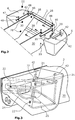
- Fig. 2 shows a perspective view of the arrangement and attachment of the weight weights 6 at the rear end 10 of the machine frame 2.
- the weighting weight 6 has an impact-resistant casing 8 which forms part of the body 4 and which receives a concrete core 16.
- the concrete core 16 preferably has reinforcement structures 20 that are integrated into the concrete core 16.
- the reinforcement structures 20 are made of Fig. 3 evident.
- the reinforcement structures 20 can be connected with fastening means 18 which are provided for fastening the weighting weight 6 to the machine frame 2. These fastening means 18 can be anchored on the casing 8 and / or in the concrete core 16. Screw connections are preferably used as fastening means 18.
- Fig. 3 shows an embodiment in which three threaded nuts 22 interacting with screw bolts 28 are fastened, in particular welded, to an anchor plate 24 as fastening means 18, wherein the anchor plate 24 can be connected to the reinforcement structures 20 integrated in the concrete core 16.
- the anchor plate 24 can be attached to the outside of the casing 8 on the side of the weight 6 facing the machine frame 2, or preferably in the concrete core 16, as shown in FIG Fig. 6 can be seen, be integrated, with corresponding recesses in the weight 6 allow the screw bolts 28 to be screwed into the threaded nuts 22.
- the weight 6 can be adjusted via the in Fig. 2 apparent screw bolts 28, which are inserted through through holes 29 in the side walls 30 of the machine frame 2, for example, are fastened to the machine frame 2.
- a plate 46 firmly connected to the machine frame 2 via screw bolts 48 can be attached to the top of the weight 6 Weighting weight 6 be screwed to relieve the bolt 28 of transverse forces.
- the casing 8 has walls 26 made of plastic material made of an impact-resistant and / or fiber-reinforced plastic.
- the walls made of plastic material form an impact-resistant casing 8 of the concrete core 16, so that the weight 6 can absorb high impact forces without any functional failure. Even if the concrete core 16 breaks in the event of a violent collision of the soil compacting machine, it is held together by the casing 8 of the concrete core 16, in particular in connection with the reinforcing structures 20, in such a way that no immediate business interruption and work interruptions are required.
- a damaged weight 6 can be exchanged after the work has been completed or if a corresponding replacement part is available.
- the casing 8 can also have an in Fig. 4 have shown removable lid 40, which can also cover a filling opening for concrete.
- the cover 40 does not have to extend over the entire upper surface of the casing 8 when the concrete core 16 is filled in in the liquefied state.
- fastening means 42 e.g. Threaded bushings which are connected to anchors 21 in the concrete core 16 may be arranged. These fastening means 42 allow lifting devices to be coupled in order to transport a weighting weight 6 or to hold it during assembly or disassembly.
- the plastic surface of the casing 8 also enables the weighting weight 6 to be painted as a component of the body 4, so that the weighting weight 6 also visually forms a body part.
- the sheath 8 can be made of impact-resistant or impact-resistant plastics, such as those from the overview "Technical plastics from Thyssen Krupp Plastics”: http://www.thyssenkruppplastics.de/fileadmin/inhalte/07_Publikationen/06_Pros pekte / 0750_Techn_Kunstscher_150dpi.pdf can be seen.
- suitable plastics with a tensile strength of, for example, over 40 N / mm 2 according to ISO 527 or plastics in which no breakage can be determined in an impact strength test according to ISO 179.
- thermoplastics, thermoplastic elastomers and thermosets are suitable plastics.
- a particularly impact-resistant plastic is, for example, polycarbonate.
- the wall thickness of the plastic walls can be calculated based on the strength values of the plastic and the impact load to be withstood.
- the wall thickness can also be based on the fact that the casing 8 cannot burst or excessively deform when it is filled with the filler material, in particular concrete.
- the casing 8 can also be supported from the outside when the concrete core 16 is poured, until the concrete core 16 has hardened.
- Figs. 4th and 6th show a schematic cross section through the weight 6 across the machine frame 2 with alternative anchors 32, 34.
- the anchoring 32 consists of a holder 36 which is integrated into the wall 26 and is connected to the schematically illustrated reinforcement structures 20 in the concrete core 16, for example, via at least one connecting bracket 38 which extends into the concrete core 16.
- Figs. 5a and 5b show the connecting bracket 38 and three-dimensionally an example of the holder 36.
- Fig. 6 shows an alternative embodiment in which an anchor 34, which can consist of a plastic or metal structure, is integrated into the wall 26 and protrudes into the concrete core 16.
- the anchorage 34 can have openings 44 in the area of the concrete core 16, through which concrete can pass and thus enables a particularly firm anchorage in the concrete core 16.
- This anchoring 34 is particularly advantageous if no wall of the casing 8 is provided on the side facing the machine frame 2.
- Fig. 6 an example of the arrangement of the anchor plate 24 in the concrete core 16 is also shown.
- the concrete core 16 preferably extends to the contact surface of the weight 6 on the machine frame 2, so that the concrete core 16 can be supported directly on the machine frame 2.
- the casing 8 is therefore at least partially recessed, so that the casing 8 does not completely surround the concrete core 16.
- the recesses simultaneously form the filling openings for filling in the not yet solidified concrete in the preferred method of manufacturing the weight weights 6.
- the sheathing 8 can also only be cut out in the areas in which the fastening means 18 pass through, for example in the form of the three screw bolts 28, so that the concrete core 16 is only flush with the casing 8 with a larger area on the machine frame in the vicinity of the fastening means 18 2 rests.
- the weighting weight 6 can then be almost completely encompassed by the casing 8.
Landscapes
- Engineering & Computer Science (AREA)
- Structural Engineering (AREA)
- Life Sciences & Earth Sciences (AREA)
- Civil Engineering (AREA)
- Environmental & Geological Engineering (AREA)
- Agronomy & Crop Science (AREA)
- Architecture (AREA)
- Soil Sciences (AREA)
- General Life Sciences & Earth Sciences (AREA)
- Mining & Mineral Resources (AREA)
- Paleontology (AREA)
- General Engineering & Computer Science (AREA)
- Road Paving Machines (AREA)
- Machines For Laying And Maintaining Railways (AREA)
- Railway Tracks (AREA)
Claims (15)
- Engin de compactage de sol, en particulier compacteur à rouleau (1), doté d'un châssis de machine (2), lequel porte une carrosserie (4), dans lequel au moins un poids de lestage (6) adapté à la carrosserie (4) est fixé au châssis de machine (2),
caractérisé en ce que l'au moins un poids de lestage (6) comporte au moins en partie une gaine (8) résistante aux chocs, laquelle forme un composant de la carrosserie (4), dans lequel la gaine (8) résistante aux chocs est remplie d'un matériau de remplissage alourdissant et la gaine (8) résistante aux chocs protège le matériau de remplissage des charges d'impact. - Engin de compactage de sol selon la revendication 1, caractérisé en ce que le poids de lestage (6) est fixé à l'extrémité arrière du châssis de machine (2).
- Engin de compactage de sol selon la revendication 1, caractérisé en ce que le matériau de remplissage alourdissant comporte un noyau de béton (16).
- Engin de compactage de sol selon la revendication 3, caractérisé en ce que des moyens de fixation (18) destinés à fixer le poids de lestage (6) au châssis de machine (2) sont prévus, lesquels sont ancrés dans le noyau de béton (16).
- Engin de compactage de sol selon l'une des revendications 3 ou 4, caractérisé en ce que le noyau de béton (16) comporte des structures de renforcement (20).
- Engin de compactage de sol selon l'une des revendications 3 à 5, caractérisé en ce que la gaine (8) comporte des parois (26) avec des ancrages (32, 34) pénétrant vers l'intérieur, lesquels sont reliés au noyau de béton (16).
- Engin de compactage de sol selon l'une des revendications 1 à 6, caractérisé en ce que la gaine (8) résistante aux chocs comporte des parois en matériau plastique.
- Engin de compactage de sol selon la revendication 7, caractérisé en ce que les parois (26) de la gaine (8) comportent une structure de renforcement (20) incorporée, dans lequel les parois (26) comportent de préférence un plastique renforcé de fibres.
- Procédé de fabrication d'un poids de lestage (6) pour un engin de compactage de sol, en particulier pour un compacteur à rouleau (1), doté d'un châssis de machine (2) portant une carrosserie (4), dans lequel au moins un poids de lestage (6) adapté à la carrosserie (4) est fixé au châssis de machine (2),
caractérisé en ce que le poids de lestage (6) est bordé au moins en partie par une gaine (8) résistante aux chocs adaptée à la forme de la carrosserie (4), laquelle est utilisée comme composant de la carrosserie (4). - Procédé selon la revendication 9, caractérisé en ce qu'un noyau de béton (16) doté de structures de renforcement (20) intégrées est utilisé comme matériau de remplissage.
- Procédé selon l'une des revendications 9 à 10, caractérisé en ce que la gaine (8) entourant principalement le noyau de béton (16) est utilisée comme moule de coulée pour un noyau de béton (16), dans lequel un noyau de béton (16) est formé comme matériau de remplissage alourdissant dans la gaine (8) par coulage de béton non encore solidifié ou en ce qu'un noyau de béton (16) déjà solidifié et adapté à la gaine est inséré.
- Procédé selon l'une des revendications 9 à 11, caractérisé en ce qu'un plastique résistant aux chocs ou un plastique renforcé de fibres est utilisé pour les parois (26) de la gaine (8) résistante aux chocs.
- Procédé selon l'une des revendications 9 à 12, caractérisé en ce que la gaine (8) résistante aux chocs est prévue dotée d'une couche adhésive sur la face intérieure avant qu'un matériau de remplissage se solidifiant postérieurement ne soit coulé ou en ce qu'après la coulée et la solidification du matériau de remplissage, une fente entre la gaine (8) et le matériau de remplissage, résultant d'un processus de contraction ou se produisant après l'insertion d'un noyau de béton (16) préfabriqué, est remplie d'adhésif.
- Procédé selon l'une des revendications 9 à 13, caractérisé en ce que pour la pose du poids de lestage (6) dans la gaine (8) résistante aux chocs une structure de renforcement (20) pour le matériau de remplissage est d'abord insérée, la structure de renforcement (20) est prévue pour être fixée au châssis de machine (2) avec des moyens de fixation (18) avant ou après l'installation et en ce qu'ensuite le matériau de remplissage en cours de solidification est coulé dans la gaine (8) avec la structure de renforcement (20) insérée.
- Procédé selon l'une des revendications 9 à 14, caractérisé en ce que des ancrages (32, 34) dépassant depuis les parois (26) de la gaine (8) vers l'intérieur sont utilisés, lesquels sont entourés lors du moulage du matériau de remplissage en cours de solidification, par lesquels après la solidification du matériau de remplissage une liaison rigide est formée entre les parois (26) de la gaine (8) et le matériau de remplissage solidifié.
Applications Claiming Priority (1)
| Application Number | Priority Date | Filing Date | Title |
|---|---|---|---|
| DE102016210906.5A DE102016210906A1 (de) | 2016-06-17 | 2016-06-17 | Bodenverdichtungsmaschine, sowie Verfahren zum Herstellen eines Beschwerungsgewichtes für eine Bodenverdichtungsmaschine |
Publications (2)
| Publication Number | Publication Date |
|---|---|
| EP3258015A1 EP3258015A1 (fr) | 2017-12-20 |
| EP3258015B1 true EP3258015B1 (fr) | 2020-09-02 |
Family
ID=58668789
Family Applications (1)
| Application Number | Title | Priority Date | Filing Date |
|---|---|---|---|
| EP17169222.1A Active EP3258015B1 (fr) | 2016-06-17 | 2017-05-03 | Machine de compactage de sol et procédé de fabrication d'un poids de lestage pour une machine de compactage de sol |
Country Status (3)
| Country | Link |
|---|---|
| EP (1) | EP3258015B1 (fr) |
| CN (2) | CN107130499B (fr) |
| DE (1) | DE102016210906A1 (fr) |
Cited By (1)
| Publication number | Priority date | Publication date | Assignee | Title |
|---|---|---|---|---|
| FR3141672A1 (fr) * | 2022-11-08 | 2024-05-10 | Pateer France | Élement de lestage comportant un corps creux rotomoulé rempli au moins en partie de béton solidifié en place |
Families Citing this family (1)
| Publication number | Priority date | Publication date | Assignee | Title |
|---|---|---|---|---|
| DE102016210906A1 (de) * | 2016-06-17 | 2017-12-21 | Hamm Ag | Bodenverdichtungsmaschine, sowie Verfahren zum Herstellen eines Beschwerungsgewichtes für eine Bodenverdichtungsmaschine |
Family Cites Families (8)
| Publication number | Priority date | Publication date | Assignee | Title |
|---|---|---|---|---|
| FR2133535B1 (fr) * | 1971-04-15 | 1975-02-21 | Richier Sa | |
| BR9502171A (pt) | 1995-05-31 | 1997-08-26 | Dynapac Equipamentos Ind Ltda | Sistema de lastro para máquina de compactação |
| DE102004007389A1 (de) * | 2004-02-11 | 2005-09-15 | Ab-Polymerchemie Gmbh | Verfahren zum Herstellen eines Formteils aus Beton und/oder Mörtel mit einem zumindest bereichsweisen Oberflächenschutz und Verwendung desselben |
| US20170009406A1 (en) * | 2014-02-17 | 2017-01-12 | Volvo Construction Equipment Ab | Pneumatic tire compactor with water ballast |
| DE102014216439A1 (de) * | 2014-08-19 | 2016-02-25 | Hamm Ag | Bodenverdichter |
| CN204059157U (zh) * | 2014-09-01 | 2014-12-31 | 常林股份有限公司 | 一种钢轮压路机的部件布置结构 |
| US9469947B2 (en) * | 2014-10-13 | 2016-10-18 | Caterpillar Paving Products Inc. | Modular compactor frame construction |
| DE102016210906A1 (de) * | 2016-06-17 | 2017-12-21 | Hamm Ag | Bodenverdichtungsmaschine, sowie Verfahren zum Herstellen eines Beschwerungsgewichtes für eine Bodenverdichtungsmaschine |
-
2016
- 2016-06-17 DE DE102016210906.5A patent/DE102016210906A1/de not_active Withdrawn
-
2017
- 2017-05-03 EP EP17169222.1A patent/EP3258015B1/fr active Active
- 2017-06-13 CN CN201710442827.1A patent/CN107130499B/zh active Active
- 2017-06-13 CN CN201720682512.XU patent/CN208266639U/zh not_active Withdrawn - After Issue
Non-Patent Citations (1)
| Title |
|---|
| None * |
Cited By (2)
| Publication number | Priority date | Publication date | Assignee | Title |
|---|---|---|---|---|
| FR3141672A1 (fr) * | 2022-11-08 | 2024-05-10 | Pateer France | Élement de lestage comportant un corps creux rotomoulé rempli au moins en partie de béton solidifié en place |
| EP4368480A1 (fr) * | 2022-11-08 | 2024-05-15 | Pateer France | Élement de lestage comportant un corps creux rotomoulé rempli au moins en partie de béton solidifié en place |
Also Published As
| Publication number | Publication date |
|---|---|
| CN208266639U (zh) | 2018-12-21 |
| CN107130499B (zh) | 2020-03-31 |
| DE102016210906A1 (de) | 2017-12-21 |
| CN107130499A (zh) | 2017-09-05 |
| EP3258015A1 (fr) | 2017-12-20 |
Similar Documents
| Publication | Publication Date | Title |
|---|---|---|
| WO2019030054A1 (fr) | Rail porteur pour une plateforme de robot déplaçable par translation | |
| DE69007748T2 (de) | Stahlschutzplankeneinrichtung. | |
| EP3258015B1 (fr) | Machine de compactage de sol et procédé de fabrication d'un poids de lestage pour une machine de compactage de sol | |
| DE69515426T2 (de) | Versetzbahres Fahrbahnbegrenzungselement, Fahrbahnbegrenzung damit hergestellt und Verfahren zur Herstellung | |
| EP2416933B1 (fr) | Coffrage pour une pièce en béton de précision formant une traverse de chemin de fer | |
| EP2158363B1 (fr) | Système de retenue de véhicules rempli ou remplissable destiné à délimiter des voies de circulation | |
| DE102015100277A1 (de) | Betonwand und Herstellungsverfahren mittels Gleitschalung | |
| DE102005020917A1 (de) | Schutzplankenanordnung | |
| EP2025816B1 (fr) | Procédé de fabrication d'un élément de muret et élément de muret fabriqué après le procédé pour un muret de séparation du trafic | |
| EP3702187B1 (fr) | Renforcement de protection contre les chocs d'une construction de véhicule ainsi que procédé de fabrication de raccordement associé | |
| EP2898158B1 (fr) | Elément de fixation pour un dispositif de sécurité | |
| DE102010029789A1 (de) | Frontträger für ein Kraftfahrzeug | |
| DE102004010927B4 (de) | Verfahren und Vorrichtung zum Erstellen von insbesondere viertel-, halb- oder vollgewendelten Ortbeton-Treppen | |
| EP3135819B1 (fr) | Tuyau de remplissage et procédé de fabrication d'une colonne de remplissage dans le sol | |
| EP3377228B1 (fr) | Cuve de broyage | |
| EP1724416A2 (fr) | Système de fondation pour fixer un objet du type tige ou poteau dans le sol et élément de fixation creux correspondant | |
| EP3774691B1 (fr) | Corps en plaques | |
| EP3282063B1 (fr) | Treillis métallique pourvu de corps de pression ainsi que structure de chaussée | |
| DE3615490C2 (de) | Verfahren zum Verfestigen des Fußbereichs eines Ortbetonelementes in einer Bohrung und Vorrichtung zur Durchführung des Verfahrens | |
| EP3030722A1 (fr) | Fondations de machine sur plaque d'assise | |
| DE8915872U1 (de) | Schalungsvorrichtung zur Oberflächengestaltung wenigstens eines von zwei miteinander zu verbindenden Baukörpern aus Beton oder anderen aushärtbaren Werkstoffen | |
| DE2310840A1 (de) | Schleisschutz-verfahren zu seiner herstellung und anwendung | |
| DE2424245C3 (de) | Pfahlverbindung zwischen Pfahlabschnitten eines bewehrten Betonpfahls | |
| WO2024132441A1 (fr) | Stabilisateur de roulis | |
| DE2355771B2 (de) | Aus rohrprofilen bestehender schutzrahmen fuer schlepper und baumaschinen |
Legal Events
| Date | Code | Title | Description |
|---|---|---|---|
| PUAI | Public reference made under article 153(3) epc to a published international application that has entered the european phase |
Free format text: ORIGINAL CODE: 0009012 |
|
| STAA | Information on the status of an ep patent application or granted ep patent |
Free format text: STATUS: THE APPLICATION HAS BEEN PUBLISHED |
|
| STAA | Information on the status of an ep patent application or granted ep patent |
Free format text: STATUS: REQUEST FOR EXAMINATION WAS MADE |
|
| AK | Designated contracting states |
Kind code of ref document: A1 Designated state(s): AL AT BE BG CH CY CZ DE DK EE ES FI FR GB GR HR HU IE IS IT LI LT LU LV MC MK MT NL NO PL PT RO RS SE SI SK SM TR |
|
| AX | Request for extension of the european patent |
Extension state: BA ME |
|
| 17P | Request for examination filed |
Effective date: 20171207 |
|
| RBV | Designated contracting states (corrected) |
Designated state(s): AL AT BE BG CH CY CZ DE DK EE ES FI FR GB GR HR HU IE IS IT LI LT LU LV MC MK MT NL NO PL PT RO RS SE SI SK SM TR |
|
| GRAP | Despatch of communication of intention to grant a patent |
Free format text: ORIGINAL CODE: EPIDOSNIGR1 |
|
| STAA | Information on the status of an ep patent application or granted ep patent |
Free format text: STATUS: GRANT OF PATENT IS INTENDED |
|
| RIC1 | Information provided on ipc code assigned before grant |
Ipc: E02D 3/026 20060101AFI20180523BHEP |
|
| INTG | Intention to grant announced |
Effective date: 20180615 |
|
| TPAC | Observations filed by third parties |
Free format text: ORIGINAL CODE: EPIDOSNTIPA |
|
| GRAS | Grant fee paid |
Free format text: ORIGINAL CODE: EPIDOSNIGR3 |
|
| 17Q | First examination report despatched |
Effective date: 20181017 |
|
| GRAJ | Information related to disapproval of communication of intention to grant by the applicant or resumption of examination proceedings by the epo deleted |
Free format text: ORIGINAL CODE: EPIDOSDIGR1 |
|
| GRAL | Information related to payment of fee for publishing/printing deleted |
Free format text: ORIGINAL CODE: EPIDOSDIGR3 |
|
| STAA | Information on the status of an ep patent application or granted ep patent |
Free format text: STATUS: EXAMINATION IS IN PROGRESS |
|
| INTC | Intention to grant announced (deleted) | ||
| GRAP | Despatch of communication of intention to grant a patent |
Free format text: ORIGINAL CODE: EPIDOSNIGR1 |
|
| STAA | Information on the status of an ep patent application or granted ep patent |
Free format text: STATUS: GRANT OF PATENT IS INTENDED |
|
| INTG | Intention to grant announced |
Effective date: 20200409 |
|
| GRAS | Grant fee paid |
Free format text: ORIGINAL CODE: EPIDOSNIGR3 |
|
| GRAA | (expected) grant |
Free format text: ORIGINAL CODE: 0009210 |
|
| STAA | Information on the status of an ep patent application or granted ep patent |
Free format text: STATUS: THE PATENT HAS BEEN GRANTED |
|
| AK | Designated contracting states |
Kind code of ref document: B1 Designated state(s): AL AT BE BG CH CY CZ DE DK EE ES FI FR GB GR HR HU IE IS IT LI LT LU LV MC MK MT NL NO PL PT RO RS SE SI SK SM TR |
|
| REG | Reference to a national code |
Ref country code: GB Ref legal event code: FG4D Free format text: NOT ENGLISH |
|
| REG | Reference to a national code |
Ref country code: AT Ref legal event code: REF Ref document number: 1308936 Country of ref document: AT Kind code of ref document: T Effective date: 20200915 Ref country code: CH Ref legal event code: EP |
|
| REG | Reference to a national code |
Ref country code: DE Ref legal event code: R096 Ref document number: 502017006995 Country of ref document: DE |
|
| REG | Reference to a national code |
Ref country code: IE Ref legal event code: FG4D Free format text: LANGUAGE OF EP DOCUMENT: GERMAN |
|
| REG | Reference to a national code |
Ref country code: SE Ref legal event code: TRGR |
|
| REG | Reference to a national code |
Ref country code: LT Ref legal event code: MG4D |
|
| PG25 | Lapsed in a contracting state [announced via postgrant information from national office to epo] |
Ref country code: LT Free format text: LAPSE BECAUSE OF FAILURE TO SUBMIT A TRANSLATION OF THE DESCRIPTION OR TO PAY THE FEE WITHIN THE PRESCRIBED TIME-LIMIT Effective date: 20200902 Ref country code: FI Free format text: LAPSE BECAUSE OF FAILURE TO SUBMIT A TRANSLATION OF THE DESCRIPTION OR TO PAY THE FEE WITHIN THE PRESCRIBED TIME-LIMIT Effective date: 20200902 Ref country code: GR Free format text: LAPSE BECAUSE OF FAILURE TO SUBMIT A TRANSLATION OF THE DESCRIPTION OR TO PAY THE FEE WITHIN THE PRESCRIBED TIME-LIMIT Effective date: 20201203 Ref country code: NO Free format text: LAPSE BECAUSE OF FAILURE TO SUBMIT A TRANSLATION OF THE DESCRIPTION OR TO PAY THE FEE WITHIN THE PRESCRIBED TIME-LIMIT Effective date: 20201202 Ref country code: BG Free format text: LAPSE BECAUSE OF FAILURE TO SUBMIT A TRANSLATION OF THE DESCRIPTION OR TO PAY THE FEE WITHIN THE PRESCRIBED TIME-LIMIT Effective date: 20201202 Ref country code: HR Free format text: LAPSE BECAUSE OF FAILURE TO SUBMIT A TRANSLATION OF THE DESCRIPTION OR TO PAY THE FEE WITHIN THE PRESCRIBED TIME-LIMIT Effective date: 20200902 |
|
| REG | Reference to a national code |
Ref country code: NL Ref legal event code: MP Effective date: 20200902 |
|
| PG25 | Lapsed in a contracting state [announced via postgrant information from national office to epo] |
Ref country code: RS Free format text: LAPSE BECAUSE OF FAILURE TO SUBMIT A TRANSLATION OF THE DESCRIPTION OR TO PAY THE FEE WITHIN THE PRESCRIBED TIME-LIMIT Effective date: 20200902 Ref country code: PL Free format text: LAPSE BECAUSE OF FAILURE TO SUBMIT A TRANSLATION OF THE DESCRIPTION OR TO PAY THE FEE WITHIN THE PRESCRIBED TIME-LIMIT Effective date: 20200902 Ref country code: LV Free format text: LAPSE BECAUSE OF FAILURE TO SUBMIT A TRANSLATION OF THE DESCRIPTION OR TO PAY THE FEE WITHIN THE PRESCRIBED TIME-LIMIT Effective date: 20200902 |
|
| PG25 | Lapsed in a contracting state [announced via postgrant information from national office to epo] |
Ref country code: RO Free format text: LAPSE BECAUSE OF FAILURE TO SUBMIT A TRANSLATION OF THE DESCRIPTION OR TO PAY THE FEE WITHIN THE PRESCRIBED TIME-LIMIT Effective date: 20200902 Ref country code: PT Free format text: LAPSE BECAUSE OF FAILURE TO SUBMIT A TRANSLATION OF THE DESCRIPTION OR TO PAY THE FEE WITHIN THE PRESCRIBED TIME-LIMIT Effective date: 20210104 Ref country code: SM Free format text: LAPSE BECAUSE OF FAILURE TO SUBMIT A TRANSLATION OF THE DESCRIPTION OR TO PAY THE FEE WITHIN THE PRESCRIBED TIME-LIMIT Effective date: 20200902 Ref country code: EE Free format text: LAPSE BECAUSE OF FAILURE TO SUBMIT A TRANSLATION OF THE DESCRIPTION OR TO PAY THE FEE WITHIN THE PRESCRIBED TIME-LIMIT Effective date: 20200902 |
|
| PG25 | Lapsed in a contracting state [announced via postgrant information from national office to epo] |
Ref country code: AL Free format text: LAPSE BECAUSE OF FAILURE TO SUBMIT A TRANSLATION OF THE DESCRIPTION OR TO PAY THE FEE WITHIN THE PRESCRIBED TIME-LIMIT Effective date: 20200902 Ref country code: ES Free format text: LAPSE BECAUSE OF FAILURE TO SUBMIT A TRANSLATION OF THE DESCRIPTION OR TO PAY THE FEE WITHIN THE PRESCRIBED TIME-LIMIT Effective date: 20200902 Ref country code: IS Free format text: LAPSE BECAUSE OF FAILURE TO SUBMIT A TRANSLATION OF THE DESCRIPTION OR TO PAY THE FEE WITHIN THE PRESCRIBED TIME-LIMIT Effective date: 20210102 |
|
| REG | Reference to a national code |
Ref country code: DE Ref legal event code: R097 Ref document number: 502017006995 Country of ref document: DE |
|
| PG25 | Lapsed in a contracting state [announced via postgrant information from national office to epo] |
Ref country code: SK Free format text: LAPSE BECAUSE OF FAILURE TO SUBMIT A TRANSLATION OF THE DESCRIPTION OR TO PAY THE FEE WITHIN THE PRESCRIBED TIME-LIMIT Effective date: 20200902 |
|
| PLBE | No opposition filed within time limit |
Free format text: ORIGINAL CODE: 0009261 |
|
| STAA | Information on the status of an ep patent application or granted ep patent |
Free format text: STATUS: NO OPPOSITION FILED WITHIN TIME LIMIT |
|
| 26N | No opposition filed |
Effective date: 20210603 |
|
| PG25 | Lapsed in a contracting state [announced via postgrant information from national office to epo] |
Ref country code: DK Free format text: LAPSE BECAUSE OF FAILURE TO SUBMIT A TRANSLATION OF THE DESCRIPTION OR TO PAY THE FEE WITHIN THE PRESCRIBED TIME-LIMIT Effective date: 20200902 Ref country code: SI Free format text: LAPSE BECAUSE OF FAILURE TO SUBMIT A TRANSLATION OF THE DESCRIPTION OR TO PAY THE FEE WITHIN THE PRESCRIBED TIME-LIMIT Effective date: 20200902 |
|
| PG25 | Lapsed in a contracting state [announced via postgrant information from national office to epo] |
Ref country code: IT Free format text: LAPSE BECAUSE OF FAILURE TO SUBMIT A TRANSLATION OF THE DESCRIPTION OR TO PAY THE FEE WITHIN THE PRESCRIBED TIME-LIMIT Effective date: 20200902 |
|
| REG | Reference to a national code |
Ref country code: CH Ref legal event code: PL |
|
| GBPC | Gb: european patent ceased through non-payment of renewal fee |
Effective date: 20210503 |
|
| PG25 | Lapsed in a contracting state [announced via postgrant information from national office to epo] |
Ref country code: LI Free format text: LAPSE BECAUSE OF NON-PAYMENT OF DUE FEES Effective date: 20210531 Ref country code: MC Free format text: LAPSE BECAUSE OF FAILURE TO SUBMIT A TRANSLATION OF THE DESCRIPTION OR TO PAY THE FEE WITHIN THE PRESCRIBED TIME-LIMIT Effective date: 20200902 Ref country code: LU Free format text: LAPSE BECAUSE OF NON-PAYMENT OF DUE FEES Effective date: 20210503 Ref country code: CH Free format text: LAPSE BECAUSE OF NON-PAYMENT OF DUE FEES Effective date: 20210531 |
|
| REG | Reference to a national code |
Ref country code: BE Ref legal event code: MM Effective date: 20210531 |
|
| PG25 | Lapsed in a contracting state [announced via postgrant information from national office to epo] |
Ref country code: IE Free format text: LAPSE BECAUSE OF NON-PAYMENT OF DUE FEES Effective date: 20210503 Ref country code: GB Free format text: LAPSE BECAUSE OF NON-PAYMENT OF DUE FEES Effective date: 20210503 |
|
| PG25 | Lapsed in a contracting state [announced via postgrant information from national office to epo] |
Ref country code: FR Free format text: LAPSE BECAUSE OF NON-PAYMENT OF DUE FEES Effective date: 20210531 |
|
| PG25 | Lapsed in a contracting state [announced via postgrant information from national office to epo] |
Ref country code: BE Free format text: LAPSE BECAUSE OF NON-PAYMENT OF DUE FEES Effective date: 20210531 |
|
| PG25 | Lapsed in a contracting state [announced via postgrant information from national office to epo] |
Ref country code: HU Free format text: LAPSE BECAUSE OF FAILURE TO SUBMIT A TRANSLATION OF THE DESCRIPTION OR TO PAY THE FEE WITHIN THE PRESCRIBED TIME-LIMIT; INVALID AB INITIO Effective date: 20170503 |
|
| P01 | Opt-out of the competence of the unified patent court (upc) registered |
Effective date: 20230502 |
|
| PG25 | Lapsed in a contracting state [announced via postgrant information from national office to epo] |
Ref country code: NL Free format text: LAPSE BECAUSE OF NON-PAYMENT OF DUE FEES Effective date: 20200923 Ref country code: CY Free format text: LAPSE BECAUSE OF FAILURE TO SUBMIT A TRANSLATION OF THE DESCRIPTION OR TO PAY THE FEE WITHIN THE PRESCRIBED TIME-LIMIT Effective date: 20200902 |
|
| REG | Reference to a national code |
Ref country code: AT Ref legal event code: MM01 Ref document number: 1308936 Country of ref document: AT Kind code of ref document: T Effective date: 20220503 |
|
| PG25 | Lapsed in a contracting state [announced via postgrant information from national office to epo] |
Ref country code: AT Free format text: LAPSE BECAUSE OF NON-PAYMENT OF DUE FEES Effective date: 20220503 |
|
| PG25 | Lapsed in a contracting state [announced via postgrant information from national office to epo] |
Ref country code: MK Free format text: LAPSE BECAUSE OF FAILURE TO SUBMIT A TRANSLATION OF THE DESCRIPTION OR TO PAY THE FEE WITHIN THE PRESCRIBED TIME-LIMIT Effective date: 20200902 |
|
| PG25 | Lapsed in a contracting state [announced via postgrant information from national office to epo] |
Ref country code: MT Free format text: LAPSE BECAUSE OF FAILURE TO SUBMIT A TRANSLATION OF THE DESCRIPTION OR TO PAY THE FEE WITHIN THE PRESCRIBED TIME-LIMIT Effective date: 20200902 |
|
| PGFP | Annual fee paid to national office [announced via postgrant information from national office to epo] |
Ref country code: DE Payment date: 20250515 Year of fee payment: 9 |
|
| PGFP | Annual fee paid to national office [announced via postgrant information from national office to epo] |
Ref country code: CZ Payment date: 20250417 Year of fee payment: 9 |
|
| PGFP | Annual fee paid to national office [announced via postgrant information from national office to epo] |
Ref country code: SE Payment date: 20250522 Year of fee payment: 9 |
|
| PG25 | Lapsed in a contracting state [announced via postgrant information from national office to epo] |
Ref country code: TR Free format text: LAPSE BECAUSE OF FAILURE TO SUBMIT A TRANSLATION OF THE DESCRIPTION OR TO PAY THE FEE WITHIN THE PRESCRIBED TIME-LIMIT Effective date: 20200902 |