EP3258018A1 - Armaturenkörper für eine sanitärarmatur, aufweisend einen deckel mit einem hohlraum - Google Patents
Armaturenkörper für eine sanitärarmatur, aufweisend einen deckel mit einem hohlraum Download PDFInfo
- Publication number
- EP3258018A1 EP3258018A1 EP17176504.3A EP17176504A EP3258018A1 EP 3258018 A1 EP3258018 A1 EP 3258018A1 EP 17176504 A EP17176504 A EP 17176504A EP 3258018 A1 EP3258018 A1 EP 3258018A1
- Authority
- EP
- European Patent Office
- Prior art keywords
- partially
- membrane
- lid
- waterway
- fitting
- Prior art date
- Legal status (The legal status is an assumption and is not a legal conclusion. Google has not performed a legal analysis and makes no representation as to the accuracy of the status listed.)
- Granted
Links
Images

Classifications
-
- E—FIXED CONSTRUCTIONS
- E03—WATER SUPPLY; SEWERAGE
- E03C—DOMESTIC PLUMBING INSTALLATIONS FOR FRESH WATER OR WASTE WATER; SINKS
- E03C1/00—Domestic plumbing installations for fresh water or waste water; Sinks
- E03C1/02—Plumbing installations for fresh water
-
- E—FIXED CONSTRUCTIONS
- E03—WATER SUPPLY; SEWERAGE
- E03B—INSTALLATIONS OR METHODS FOR OBTAINING, COLLECTING, OR DISTRIBUTING WATER
- E03B7/00—Water main or service pipe systems
- E03B7/07—Arrangement of devices, e.g. filters, flow controls, measuring devices, siphons or valves, in the pipe systems
- E03B7/075—Arrangement of devices for control of pressure or flow rate
-
- E—FIXED CONSTRUCTIONS
- E03—WATER SUPPLY; SEWERAGE
- E03C—DOMESTIC PLUMBING INSTALLATIONS FOR FRESH WATER OR WASTE WATER; SINKS
- E03C2201/00—Details, devices or methods not otherwise provided for
- E03C2201/60—Reducing noise in plumbing systems
Definitions
- the present invention relates to a fitting body for a sanitary fitting, which serves the needs-oriented provision of water.
- sanitary fittings are regularly used in the context of sinks, sinks, bathtubs and / or showers.
- Sanitary fittings may in particular be thermostatic valves, mixing valves and / or thermostatic mixing valves.
- Such sanitary fittings regularly have a hot water supply for hot water and a cold water supply for cold water.
- the hot water and the cold water are miscible to a mixed water with a desired mixed water temperature.
- the sanitary fittings may in particular have thermostatic valves and / or mixing valves.
- the sanitary fittings regularly have at least one outlet opening for the mixed water.
- the water flow or the amount of water can be adjusted by means of a volume control valve.
- the valves can be actuated by means of separate actuators or by means of a common actuator of the sanitary fittings.
- sanitary fittings can be provided with components for sound damping and pressure equalization.
- a suitable damper operates on the reflection principle and comprises a sleeve-shaped rubber sleeve, which can be inserted into the fitting connection, wherein between the sleeve and tube an air-filled chamber remains. Since air and water have very different sound propagation conditions (the wave resistance in water is about 3500 times higher than in air), the water sound impinging on the damper becomes large Part reflected and returned to the sanitary fitting. The effect of such water mufflers is frequency-dependent and increases with increasing frequency. Based on the tap sound level (overall level including all frequencies), a noise reduction of about 10 to 15 dB (A) can be achieved.
- the available space for these components space is very limited or not available, so that their placement is problematic.
- the components for soundproofing can be accommodated in the S-connections.
- these are usually arranged in the waterways or lack of space across the waterways.
- the above-described components for soundproofing could nevertheless be backwashed due to design, which can lead to an almost complete loss of effect.
- suitable components for noise reduction and pressure equalization should be installed so that they are exchangeable or to be maintained, which is problematic in sanitary fittings, such as concealed fittings or surface-mounted fittings, in chassis design, because the optimal for the operation of subsequent points not always are accessible.
- the object of the invention is therefore to solve the problems described with reference to the prior art at least partially and in particular to provide a fitting body for a sanitary fitting whose silencer or pressure damper can be installed to save space and possibly even requires no maintenance.
- the associated fitting body for a sanitary fitting has a base body with at least one at least partially open channel, wherein the at least one partially open channel is at least partially closed to form a waterway by a lid and wherein in the lid at least partially along the waterway a cavity is formed, which is at least partially along the waterway bounded by a membrane.
- the fitting body is provided in particular for a sanitary fitting, which serves the needs-oriented provision of water, in particular on a sink, sink, shower and / or bath.
- the sanitary fitting may for this purpose have a mixing valve by means of which a cold water with a cold water temperature and a hot water with a hot water temperature to a mixed water with a desired mixed water temperature are miscible.
- the cold water temperature may be 1 ° C (Celsius) to 25 ° C and / or the hot water temperature 25 ° C to 99 ° C.
- the fitting body has a base body with at least one at least partially open channel (for example, at the periphery, transversely to a longitudinal direction of the channel, along the longitudinal direction of the channel, laterally and / or laterally).
- the main body is preferably formed as a cast component and preferably as a one-piece or cast component.
- the base body can be produced in a casting tool, in particular an injection molding tool and preferably in a plastic injection molding tool.
- the at least one at least partially open channel is introduced in the base body in particular during the casting process or injection molding process by means of corresponding molding tools.
- the base body may have at least one receptacle for a cover of the at least one at least partially open channel.
- the recording may be in the manner of (at least partially formed circumferentially to the at least one at least partially open channel formed) recesses or a recess and / or an increase or a projection.
- the main body may be substantially plate-shaped or disc-shaped, wherein the at least one recess / recess or at least one increase / projection extends from the main body inwards / downwards or outside / upwards.
- the main body can be formed integrally with the recording.
- Plate-shaped or disk-shaped here means, in particular, that a spreading of the main body in a horizontal direction or width is greater than a propagation of the main body in a vertical direction or height.
- the at least one at least partially open channel is provided in particular on a surface of the base body. Furthermore, the at least one at least partially open channel is at least partially closed to form at least one waterway by a cover.
- the waterway is (only) enclosed along a flow direction of the water by means of the at least one at least partially open channel and the lid.
- several (at least partially separate) waterways are provided, which guide, for example for cold water, hot water and / or mixed water through the fitting body.
- the waterway can be circular, oval or angular in cross section.
- a cross section of the waterway is here understood to be essentially perpendicular to a flow direction or conveying direction of the waterway.
- the lid is not merely a flat closure plate, but preferably has a curved, in particular curved or angular, inner forming.
- the lid may be formed in the manner of a (hollow) plug or a (hollow) screw, which serve the closure of at least one at least partially open channel.
- one (individual) receptacle and accordingly also a (single) cover are provided per waterway.
- the cover may in particular be designed in the form of a half shell and / or extend at least partially in the direction of the at least one at least partially open channel.
- the lid forms, together with the at least one at least partially open channel in the fitting body, the at least one water path through which water can be conducted through the fitting body.
- the cover is arranged in particular in the at least one receptacle of the main body or screwed, welded, clamped and / or adhesively bonded to the main body. Furthermore, the cover, in particular in the receptacle of the base body, be encapsulated with a molding compound, such as plastic.
- the lid may be at least partially disposed in the receptacle.
- the lid is completely arranged in the receptacle.
- this is not mandatory, because at least part of a lid outer side can also protrude or protrude outwardly (longitudinally and / or laterally) over the receptacle or the projections.
- the arrangement of the lid in the receptacle has the advantage that the lid can be very easily and accurately aligned with the at least one at least partially open channel.
- the at least one lid can also be made as a casting.
- the lid can be produced in a casting tool, in particular an injection molding tool and preferably in a plastic injection molding tool.
- the lid is preferably formed with or made of metal and / or plastic.
- the lid is formed with metal, it may be made by, for example, a deep-drawing method, die-forging or the like.
- the at least one lid separates the later water leading waterway from the area in which the molding compound can be arranged.
- Such a region can be, for example, a receptacle which is at least partially filled with the molding compound.
- the lid is integrally formed. It is possible that the at least one at least partially open channel is closed by means of several lids to the outside. In particular, each waterway is thus along the flow direction of the water by means of the at least one at least partially open channel and by means of at least one lid after bounded or enclosed outside. Furthermore, in the cover at least partially, preferably completely, along the at least one water path, a cavity is formed, which serves as a muffler. This has the advantage that the noises are fought where they arise. Maintenance of the cavity is not required.
- the cavity of the lid is at least partially bounded along the waterway by a membrane.
- This (separate) membrane also has a sound-damping effect and also minimizes a pressure increase due to an expansion of the water in the waterway.
- the durability of the connection between the base body and the cover can also be increased.
- fitting bodies in which the waterway or the waterways are closed longitudinally through the lid results in a particularly large effective area.
- the channel is at least partially open laterally.
- the at least one at least partially open channel is thus at least one laterally open channel.
- Lateral (or longitudinal and / or lateral) open here means in particular that the at least one laterally open channel is designed to be open in a direction transverse to its direction of propagation within the main body. This serves to avoid undercuts of the at least one laterally open channel in a demoulding direction of the base body. Expressed in other words, this also means that the at least one laterally open channel is laterally open relative to a separating surface or parting plane of the main body and is not undercut in a viewing direction onto the dividing plane of the main body.
- the at least one laterally open channel in this case runs in particular parallel to this parting plane or parting surface and / or in particular along the parting surface.
- the membrane delimits or even separates the cavity from the waterway. This means, in particular, that the membrane prevents inflow of the water into the cavity, that is, in particular during operation, it is (only) filled with air.
- the membrane is arranged between the base body and the lid.
- the membrane is clamped or fixed between the base body and the lid.
- the membrane can be circumferentially clamped between the base body and the lid (waterproof).
- the membrane is preferably positioned predominantly freely movable, in particular starting from a central region towards an edge region fixed between the base body and the cover.
- the membrane is at least partially elastic.
- the membrane for example, at least partially made of rubber.
- the membrane forms an air cushion with the cavity.
- the cavity is filled with air and the membrane is resiliently supported by the air in the cavity (at least in a central area).
- the membrane is at least partially deflectable into the cavity by a water flowing through the waterway. As a result, a pressure increase in the water can be minimized in a particularly simple manner.
- the membrane extends along the entire closed at least partially open channel through the lid.
- the membrane can cover or close the entire at least partially open channel.
- a volume of the water path (in the fitting body) can be varied through the membrane.
- the volume of the waterway in the fitting body increases when the membrane is deflected by the water flowing through the waterway into the cavity.
- the lid has at least partially a C-shaped cross section.
- the lid can be designed in the manner of a cap.
- the Fig. 1 shows a main body 2 in a perspective view.
- the main body 2 has two laterally open channels 3, which extend parallel to a surface 12 of the main body 2 and are each surrounded by a circumferential receptacle 11.
- the two laterally open channels 3 are each with a in the Fig. 2 shown cover 5 closed.
- the Fig. 3 shows a part of a fitting body 1 in the region of one of the laterally open channels 3 of the main body 2 in a sectional view, after the two laterally open channels 3 (of which in the Fig. 3 only one is shown) was closed.
- the lid 5 has a C-shaped cross-section 9 and closes the laterally open channel 3 such that a waterway 4 is formed.
- the cover 5 is arranged on a shoulder 13 of the receptacle 11 of the main body 2.
- a membrane 7 is inserted, so that in the lid 5, a cavity 6 is formed.
- the membrane is elastic and the cavity 6 is filled with air, so that an air cushion 8 is formed by the membrane 7 and the cavity 6.
- the cover 5 is here further surrounded by a molding compound 10, so that the cover 5 is fixedly connected to the base body 2.
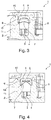
- the Fig. 4 shows the same sectional view of the fitting body 1 as the Fig. 3 However, the fitting body 1 is in a second operating state.
- the Fig. 4 is different from the Fig. 3 merely in that the membrane 7 is stretched into the cavity 6 of the lid 5 by a water located in the laterally open channel 3 or the waterway 4. Incidentally, the description of the Fig. 3 directed.
- the proposed invention is characterized in particular by a low maintenance of the muffler, a good sound attenuation and a minimized increase in pressure in the waterways.
Landscapes
- Health & Medical Sciences (AREA)
- Life Sciences & Earth Sciences (AREA)
- Engineering & Computer Science (AREA)
- Hydrology & Water Resources (AREA)
- Public Health (AREA)
- Water Supply & Treatment (AREA)
- Valve Housings (AREA)
- Domestic Plumbing Installations (AREA)
Abstract
Description
- Die vorliegende Erfindung betrifft einen Armaturenkörper für eine Sanitärarmatur, die der bedarfsgerechten Bereitstellung von Wasser dient. Solche Sanitärarmaturen werden regelmäßig im Zusammenhang mit Waschbecken, Spülbecken, Badewannen und/oder Duschen verwendet.
- Bei Sanitärarmaturen kann es sich insbesondere um Thermostatarmaturen, Mischarmaturen und/oder Thermostatmischarmaturen handeln. Solche Sanitärarmaturen weisen regelmäßig einen Warmwasserzulauf für Warmwasser und einen Kaltwasserzulauf für Kaltwasser auf. Mittels der Sanitärarmatur sind insbesondere das Warmwasser und das Kaltwasser zu einem Mischwasser mit einer gewünschten Mischwassertemperatur mischbar. Zum Mischen des Warmwassers und des Kaltwassers können die Sanitärarmaturen insbesondere Thermostatventile und/oder Mischventile aufweisen. Weiterhin weisen die Sanitärarmaturen regelmäßig mindestens eine Auslassöffnung für das Mischwasser auf. Zudem kann der Wasserdurchfluss beziehungsweise die Wassermenge mittels eines Mengenregulierventils eingestellt werden. Die Ventile können mittels separater Stellglieder oder mittels eines gemeinsamen Stellglieds der Sanitärarmaturen betätigt werden.
- Bei der Verwendung solcher Sanitärarmaturen können störende Geräusche sowie Druckschwankungen in den Wasserwegen auftreten. Aus diesem Grund können Sanitärarmaturen mit Komponenten zur Schalldämpfung und zum Druckausgleich versehen werden. Ein geeigneter Dämpfer arbeitet nach dem Reflexionsprinzip und umfasst eine hülsenförmige GummiManschette, die in den Armaturenanschluss eingeschoben werden kann, wobei zwischen Manschette und Rohr eine luftgefüllte Kammer verbleibt. Da Luft und Wasser stark unterschiedliche Schallausbreitungsbedingungen aufweisen (der Wellen-Widerstand in Wasser ist etwa 3500-mal höher als in Luft), wird der auf den Dämpfer auftreffende Wasserschall zu einem großen Teil reflektiert und zur Sanitärarmatur zurückgeleitet. Die Wirkung derartiger Wasserschalldämpfern ist frequenzabhängig und steigt mit zunehmender Frequenz an. Bezogen auf den Armaturengeräuschpegel (Gesamtpegel unter Einbeziehung aller Frequenzen) kann eine Geräuschminderung von etwa 10 bis 15 dB(A) erreicht werden.
- Allerdings ist der für diese Komponenten zur Verfügung stehende Bauraum stark begrenzt oder nicht vorhanden, sodass deren Unterbringung problematisch ist. Bei Aufputzarmaturen können die Komponenten zur Schalldämpfung in den S-Anschlüssen untergebracht werden. Bei Unterputzarmaturen sind diese in der Regel in den Wasserwegen oder bei Platzmangel quer zu den Wasserwegen angeordnet. Die vorstehend beschriebenen Komponenten zur Schalldämpfung könnten gleichwohl bauartbedingt hinterspült werden, was zu einem fast vollständigen Wirkungsverlust führen kann. Jedenfalls sollten geeignete Komponenten zur Schalldämpfung und zum Druckausgleich so montiert werden können, dass diese auszutauschen oder zu warten sind, was bei Sanitärarmaturen, wie zum Beispiel Unterputzarmaturen oder Aufputzarmaturen, in Chassis-Bauweise problematisch ist, weil die für die Wirkungsweise optimalen Stellen nachträglich nicht immer zugänglich sind.
- Aufgabe der Erfindung ist daher, die mit Bezug auf den Stand der Technik geschilderten Probleme zumindest teilweise zu lösen und insbesondere einen Armaturenkörper für eine Sanitärarmatur anzugeben, dessen Schalldämpfer bzw. Druckdämpfer platzsparender verbaut werden kann und ggf. sogar keine Wartung benötigt.
- Diese Aufgabe wird gelöst mit einem Armaturenkörper gemäß den Merkmalen des unabhängigen Patentanspruchs. Weitere vorteilhafte Ausgestaltungen des Armaturenkörpers sind in den abhängig formulierten Patentansprüchen angegeben. Es ist darauf hinzuweisen, dass die in den abhängig formulierten Patentansprüchen einzeln aufgeführten Merkmale in beliebiger technologisch sinnvoller Weise miteinander kombiniert werden können und weitere Ausgestaltungen der Erfindung definieren. Darüber hinaus werden die in den Patentansprüchen angegebenen Merkmale in der Beschreibung näher präzisiert und erläutert, wobei weitere bevorzugte Ausgestaltungen der Erfindung dargestellt werden.
- Der hierzu beitragende Armaturenkörper für eine Sanitärarmatur weist einen Grundkörper mit zumindest einem zumindest teilweise offenen Kanal auf, wobei der zumindest eine zumindest teilweise offene Kanal zumindest teilweise zur Ausbildung eines Wasserwegs durch einen Deckel verschlossen ist und wobei in dem Deckel zumindest teilweise entlang des Wasserwegs ein Hohlraum ausgebildet ist, der zumindest teilweise entlang des Wasserwegs durch eine Membran begrenzt ist.
- Der Armaturenkörper ist insbesondere für eine Sanitärarmatur vorgesehen, die der bedarfsgerechten Bereitstellung von Wasser, insbesondere an einem Waschbecken, Spülbecken, Dusche und/oder Badewanne, dient. Die Sanitärarmatur kann hierzu ein Mischventil aufweisen, mittels dem ein Kaltwasser mit einer Kaltwassertemperatur und ein Warmwasser mit einer Warmwassertemperatur zu einem Mischwasser mit einer gewünschten Mischwassertemperatur mischbar sind. Die Kaltwassertemperatur kann dabei 1 °C (Celsius) bis 25 °C und/oder die Warmwassertemperatur 25 °C bis 99 °C aufweisen.
- Der Armaturenkörper weist einen Grundkörper mit zumindest einem zumindest teilweise (bspw. am Umfang, quer zu einer Längsrichtung des Kanals, längs zu der Längsrichtung des Kanals, seitlich und/oder lateral) offenen Kanal auf. Der Grundkörper ist vorzugsweise als ein Gussbauteil und bevorzugt als ein einstückiges bzw. einteiliges Gussbauteil ausgebildet. Hierzu kann der Grundkörper in einem Gusswerkzeug, insbesondere einem Spritzgusswerkzeug und bevorzugt in einem Kunststoffspritzgusswerkzeug, hergestellt sein. Der zumindest eine zumindest teilweise offene Kanal ist insbesondere während des Gießprozesses bzw. Spritzgießprozesses mittels entsprechender Formwerkzeuge in dem Grundkörper eingebracht. Weiterhin kann der Grundkörper mindestens eine Aufnahme für einen Deckel des zumindest einen zumindest teilweise offenen Kanals aufweisen. Die Aufnahme kann in der Art einer (wenigstens teilweise umlaufend zu dem zumindest einen zumindest teilweise offenen Kanal ausgebildeten) Vertiefungen bzw. eine Ausnehmung und/oder eine Erhöhung bzw. einen Vorsprung geformt sein. Hierbei kann der Grundkörper im Wesentlichen plattenförmig beziehungsweise scheibenförmig gebildet sein, wobei sich die mindestens eine Vertiefung/Ausnehmung bzw. mindestens eine Erhöhung/Vorsprung von dem Grundkörper aus nach innen/unten beziehungsweise außen/oben erstreckt. Der Grundkörper kann mit der Aufnahme einteilig gebildet sein. Plattenförmig bzw. scheibenförmig bedeutet hier insbesondere, dass eine Ausbreitung des Grundkörpers in einer horizontalen Richtung bzw. Breite größer ist als eine Ausbreitung des Grundkörpers in einer vertikalen Richtung bzw. Höhe.
- Der zumindest eine zumindest teilweise offene Kanal ist insbesondere an einer Oberfläche des Grundkörpers vorgesehen. Weiterhin ist der zumindest eine zumindest teilweise offene Kanal mindestens teilweise zur Ausbildung zumindest eines Wasserwegs durch einen Deckel verschlossen. Der Wasserweg ist entlang einer Strömungsrichtung des Wassers (nur) mittels des zumindest einen zumindest teilweise offenen Kanals und des Deckels umschlossen. Üblicherweise sind mehrere (wenigstens teilweise getrennte) Wasserwege vorgesehen, die zum Beispiel für Kaltwasser, Warmwasser und/oder Mischwasser durch den Armaturenkörper leiten. Der Wasserweg kann im Querschnitt kreisförmig, oval oder eckig gebildet sein. Ein Querschnitt des Wasserwegs ist hier im Wesentlichen senkrecht zu einer Strömungsrichtung bzw. Förderrichtung des Wasserwegs verstanden.
- Der Deckel ist hier insbesondere nicht bloß eine ebene Verschlussplatte, sondern weist bevorzugt eine gekrümmte, insbesondere gebogene oder eckige Innenformung auf. Der Deckel kann nach Art eines (hohlen) Stopfens oder einer (hohlen) Schraube ausgebildet sein, die dem Verschluss des zumindest einen zumindest teilweise offenen Kanals dienen. Bevorzugt ist, dass pro Wasserweg eine (einzelne) Aufnahme und entsprechend auch ein (einzelner) Deckel vorgesehen sind. Der Deckel kann insbesondere halbschalenförmig ausgebildet sein und/oder sich zumindest teilweise in Richtung des zumindest einen zumindest teilweise offenen Kanals erstrecken. Der Deckel bildet zusammen mit dem zumindest einen zumindest teilweise offenen Kanal in dem Armaturenkörper den zumindest einen Wasserweg aus, durch den Wasser durch den Armaturenkörper leitbar ist. Der Deckel ist hierzu insbesondere in der mindestens einen Aufnahme des Grundkörpers angeordnet bzw. mit dem Grundkörper verschraubt, verschweißt, verklemmt und/oder verklebt. Weiterhin kann der Deckel, insbesondere in der Aufnahme des Grundkörpers, mit einer Formmasse, wie zum Beispiel Kunststoff, umgossen sein.
- Der Deckel kann zumindest teilweise in der Aufnahme angeordnet sein. Bevorzugt ist der Deckel vollständig in der Aufnahme angeordnet. Dies ist jedoch nicht zwingend, weil zumindest ein Teil einer Deckelaußenseite auch nach außen (längs und/oder seitlich) über die Aufnahme bzw. die Vorsprünge hervorstehen oder hinausragen kann. Die Anordnung des Deckels in der Aufnahme hat den Vorteil, dass der Deckel sehr einfach und exakt zu dem zumindest einen zumindest teilweise offenen Kanal ausgerichtet werden kann.
- Der mindestens eine Deckel kann ebenfalls als Gussteil hergestellt sein. Hierzu kann der Deckel in einem Gusswerkzeug, insbesondere einem Spritzwerkzeug und bevorzugt in einem Kunststoffspritzgusswerkzeug hergestellt sein. Dies ist jedoch nicht zwingend, weil der Deckel auch mittels anderer Fertigungsverfahren hergestellt sein kann. Der Deckel ist bevorzugt mit bzw. aus Metall und/oder Kunststoff gebildet. Wenn der Deckel mit Metall gebildet ist, so kann er beispielsweise mittels eines Tiefziehverfahrens, mittels Gesenkschmieden oder dergleichen hergestellt sein. Der mindestens eine Deckel trennt den später Wasser führenden Wasserweg von dem Bereich, in dem die Formmasse angeordnet sein kann. Ein solcher Bereich kann beispielsweise eine mit der Formmasse zumindest teilweise gefüllte Aufnahme sein.
- Es ist bevorzugt, dass der Deckel einteilig gebildet ist. Es ist möglich, dass der zumindest eine zumindest teilweise offene Kanal mittels mehrerer Deckel nach außen geschlossen ist. Insbesondere ist somit jeder Wasserweg entlang der Strömungsrichtung des Wassers mittels des zumindest einen zumindest teilweise offenen Kanals und mittels mindestens eines Deckels nach außen begrenzt bzw. umschlossen. Weiterhin ist in dem Deckel zumindest teilweise, bevorzugt vollständig, entlang des zumindest einen Wasserwegs, ein Hohlraum ausgebildet, der als Schalldämpfer dient. Dies hat den Vorteil, dass die Geräusche dort bekämpft werden, wo sie entstehen. Eine Wartung des Hohlraums ist nicht erforderlich.
- Weiter ist vorgesehen, dass der Hohlraum des Deckels zumindest teilweise entlang des Wasserwegs durch eine Membran begrenzt ist. Diese (separate) Membran hat ebenfalls eine schalldämpfende Wirkung und minimiert zudem einen Druckanstieg in Folge einer Ausdehnung des Wassers in dem Wasserweg. Durch die Minimierung des Druckanstiegs kann zudem die Haltbarkeit der Verbindung zwischen dem Grundkörper und dem Deckel erhöht werden. Insbesondere bei Armaturenkörpern, bei denen der Wasserweg oder die Wasserwege längs durch den Deckel verschlossen werden, ergibt sich eine besonders große Wirkfläche.
- Weiterhin ist es vorteilhaft, wenn der Kanal zumindest teilweise lateral offen ist. Bei dem zumindest einen zumindest teilweise offenen Kanal handelt es sich somit um zumindest einen lateral offenen Kanal. Lateral (beziehungsweise längs und/oder seitlich) offen bedeutet hier insbesondere, dass der zumindest eine lateral offene Kanal in einer Richtung quer zu seiner Ausbreitungsrichtung innerhalb des Grundkörpers offen gestaltet ist. Dies dient dazu, Hinterschneidungen des zumindest einen lateral offenen Kanals in einer Entformungsrichtung des Grundkörpers zu vermeiden. Mit anderen Worten ausgedrückt bedeutet dies auch, dass der zumindest eine lateral offene Kanal bezogen auf eine Trennfläche beziehungsweise Trennebene des Grundkörpers lateral offen ist und in einer Betrachtungsrichtung auf die Trennebene des Grundkörpers nicht hinterschnitten ist. Somit liegt insbesondere in der Trennebene des Grundkörpers eine maximale Querschnittsfläche des zumindest einen lateral offenen Kanals. Der zumindest eine lateral offene Kanal verläuft hierbei insbesondere parallel zu dieser Trennebene beziehungsweise Trennfläche und/oder insbesondere entlang der Trennfläche.
- Ebenfalls vorteilhaft ist es, wenn die Membran den Hohlraum von dem Wasserweg abgrenzt oder sogar abtrennt. Dies bedeutet insbesondere, dass die Membran ein Einfließen des Wassers in den Hohlraum verhindert, dieser also insbesondere während des Betriebes (nur) mit Luft gefüllt ist.
- Zudem ist es vorteilhaft, wenn die Membran zwischen dem Grundkörper und dem Deckel angeordnet ist. Ganz besonders bevorzugt ist die Membran zwischen Grundkörper und Deckel eingespannt bzw. fixiert. Die Membran kann umlaufend zwischen Grundkörper und Deckel (wasserdicht) eingeklemmt sein. Die Membran ist bevorzugt überwiegend frei beweglich positioniert, insbesondere ausgehend von einem zentralen Bereich hin zu einem zwischen Grundkörper und Deckel fixierten Randbereich.
- Weiterhin ist es vorteilhaft, wenn die Membran zumindest teilweise elastisch ist. Hierzu kann die Membran beispielsweise zumindest teilweise aus Gummi bestehen.
- Des Weiteren ist es vorteilhaft, wenn die Membran mit dem Hohlraum ein Luftpolster bildet. Dies bedeutet insbesondere, dass der Hohlraum mit Luft gefüllt ist und die Membran durch die Luft in dem Hohlraum (wenigstens in einem zentralen Bereich) federnd gelagert ist.
- Ebenfalls vorteilhaft ist es, wenn die Membran durch ein durch den Wasserweg strömendes Wasser zumindest teilweise in den Hohlraum auslenkbar ist. Hierdurch kann in besonderes einfacher Weise ein Druckanstieg in dem Wasser minimiert werden.
- Vorzugsweise erstreckt sich die Membran entlang des gesamten durch den Deckel verschlossenen zumindest teilweise offenen Kanal. Die Membran kann den gesamtem zumindest teilweise offenen Kanal überdecken bzw. verschließen.
- Weiterhin ist es vorteilhaft, wenn ein Volumen des Wasserwegs (im Armaturenkörper) durch die Membran variierbar ist. Insbesondere erhöht sich das Volumen des Wasserwegs im Armaturenkörper, wenn die Membran durch das durch den Wasserweg strömende Wasser in den Hohlraum ausgelenkt wird.
- Zudem ist es vorteilhaft, wenn der Deckel zumindest teilweise einen C-förmigen Querschnitt aufweist. Der Deckel kann nach Art einer Kappe ausgeführt sein.
- Die Erfindung sowie das technische Umfeld werden nachfolgend anhand der Figuren näher erläutert. Es ist darauf hinzuweisen, dass die Figuren eine besonders bevorzugte Ausführungsvariante der Erfindung zeigen, diese jedoch nicht darauf beschränkt ist. Dabei sind gleiche Bauteile in den Figuren mit denselben Bezugszeichen versehen. Es zeigen beispielhaft und schematisch:
- Fig. 1:
- einen Grundkörper in einer perspektivischen Darstellung;
- Fig. 2:
- einen Deckel in einer perspektivischen Darstellung;
- Fig. 3:
- einen Längsschnitt durch einen Armaturenkörper in einer ersten Betriebssituation; und
- Fig. 4:
- den Längsschnitt durch den Armaturenkörper in einer zweiten Betriebssituation.
- Die
Fig. 1 zeigt einen Grundkörper 2 in einer perspektivischen Darstellung. Der Grundkörper 2 weist zwei lateral offene Kanäle 3 auf, die sich parallel zu einer Oberfläche 12 des Grundkörpers 2 erstrecken und jeweils von einer umlaufenden Aufnahme 11 umgeben sind. Die beiden lateral offenen Kanäle 3 sind jeweils mit einem in derFig. 2 gezeigten Deckel 5 verschließbar. - Die
Fig. 3 zeigt einen Teil eines Armaturenkörpers 1 im Bereich eines der lateral offenen Kanäle 3 des Grundkörpers 2 in einer Schnittdarstellung, nachdem die zwei lateral offenen Kanäle 3 (von denen in derFig. 3 nur einer gezeigt ist) verschlossen wurde. Der Deckel 5 weist einen C-förmigen Querschnitt 9 auf und verschließt den lateral offenen Kanal 3 derart, dass ein Wasserweg 4 ausgebildet ist. Hierzu ist der Deckel 5 auf einem Absatz 13 der Aufnahme 11 des Grundkörpers 2 angeordnet. Unter dem Deckel 5 ist eine Membran 7 eingelegt, sodass in dem Deckel 5 ein Hohlraum 6 ausgebildet ist. Die Membran ist elastisch und der Hohlraum 6 mit Luft gefüllt, sodass durch die Membran 7 und den Hohlraum 6 ein Luftpolster 8 gebildet ist. Der Deckel 5 ist hier weiter mit einer Formmasse 10 umspitzt, sodass der Deckel 5 mit dem Grundkörper 2 fest verbunden ist. - Die
Fig. 4 zeigt die gleiche Schnittdarstellung des Armaturenkörpers 1 wie dieFig. 3 , wobei sich der Armaturenkörper 1 jedoch in einem zweiten Betriebszustand befindet. DieFig. 4 unterscheidet sich von derFig. 3 lediglich dadurch, dass die Membran 7 durch ein in dem lateral offenen Kanal 3 beziehungsweise dem Wasserweg 4 befindlichen Wasser in den Hohlraum 6 des Deckels 5 gedehnt ist. Im Übrigen wird auf die Beschreibung derFig. 3 verwiesen. - Die vorgeschlagene Erfindung zeichnet sich insbesondere durch einen geringen Wartungsaufwand des Schalldämpfers, eine gute Schalldämpfung und einen minimierten Druckanstieg in den Wasserwegen aus.
-
- 1
- Armaturenkörper
- 2
- Grundkörper
- 3
- Kanal
- 4
- Wasserweg
- 5
- Deckel
- 6
- Hohlraum
- 7
- Membran
- 8
- Luftpolster
- 9
- Querschnitt
- 10
- Formmasse
- 11
- Aufnahme
- 12
- Oberfläche
- 13
- Absatz
Claims (10)
- Armaturenkörper (1) für eine Sanitärarmatur, aufweisend einen Grundkörper (2) mit zumindest einem zumindest teilweise offenen Kanal (3), wobei der zumindest eine zumindest teilweise offene Kanal (3) mindestens teilweise zur Ausbildung eines Wasserwegs (4) durch einen Deckel (5) verschlossen ist, dadurch gekennzeichnet, dass in dem Deckel (5) zumindest teilweise entlang des Wasserwegs (4) ein Hohlraum (6) ausgebildet ist, der zumindest teilweise entlang des Wasserwegs (4) durch eine Membran (7) begrenzt ist.
- Armaturenkörper (1) nach Patentanspruch 1, wobei der Kanal (3) zumindest teilweise lateral offen ist.
- Armaturenkörper (1) nach einem der vorhergehenden Patentansprüche, wobei die Membran (7) den Hohlraum (6) von dem Wasserweg (4) abgrenzt.
- Armaturenkörper (1) nach einem der vorhergehenden Patentansprüche, wobei die Membran (7) zwischen dem Grundkörper (2) und dem Deckel (5) angeordnet ist.
- Armaturenkörper (1) nach einem der vorhergehenden Patentansprüche, wobei die Membran (7) zumindest teilweise elastisch ist.
- Armaturenkörper (1) nach einem der vorhergehenden Patentansprüche, wobei die Membran (7) mit dem Hohlraum (6) ein Luftpolster (8) bildet.
- Armaturenkörper (1) nach einem der vorhergehenden Patentansprüche, wobei die Membran (7) durch ein durch den Wasserweg (4) strömendes Wasser zumindest teilweise in den Hohlraum (6) auslenkbar ist.
- Armaturenkörper (1) nach einem der vorhergehenden Patentansprüche, wobei sich die Membran (7) entlang des gesamten durch den Deckel (5) verschlossenen Kanal (3) erstreckt.
- Armaturenkörper (1) nach einem der vorhergehenden Patentansprüche, wobei ein Volumen des Wasserwegs (4) durch die Membran (7) variierbar ist.
- Armaturenkörper (1) nach einem der vorhergehenden Patentansprüche, wobei der Deckel (5) zumindest teilweise einen C-förmigen Querschnitt (9) aufweist.
Applications Claiming Priority (1)
| Application Number | Priority Date | Filing Date | Title |
|---|---|---|---|
| DE102016007359.4A DE102016007359A1 (de) | 2016-06-17 | 2016-06-17 | Armaturenkörper für eine Sanitärarmatur, aufweisend einen Deckel mit einem Hohlraum |
Publications (2)
| Publication Number | Publication Date |
|---|---|
| EP3258018A1 true EP3258018A1 (de) | 2017-12-20 |
| EP3258018B1 EP3258018B1 (de) | 2021-07-28 |
Family
ID=59067607
Family Applications (1)
| Application Number | Title | Priority Date | Filing Date |
|---|---|---|---|
| EP17176504.3A Active EP3258018B1 (de) | 2016-06-17 | 2017-06-16 | Armaturenkörper für eine sanitärarmatur, aufweisend einen deckel mit einem hohlraum |
Country Status (3)
| Country | Link |
|---|---|
| EP (1) | EP3258018B1 (de) |
| DE (1) | DE102016007359A1 (de) |
| ES (1) | ES2895774T3 (de) |
Cited By (2)
| Publication number | Priority date | Publication date | Assignee | Title |
|---|---|---|---|---|
| EP3608478A1 (de) * | 2018-08-09 | 2020-02-12 | Kohler Co. | Duschsystem |
| CN113389254A (zh) * | 2020-03-11 | 2021-09-14 | 高仪股份公司 | 冲洗坐便器的功能单元及制造这种功能单元的方法 |
Citations (11)
| Publication number | Priority date | Publication date | Assignee | Title |
|---|---|---|---|---|
| DE1824211U (de) * | 1956-04-11 | 1960-12-29 | Concordia Maschinen Und Elek Z | Durchgangsventil fuer hydraulische oder pneumatische druckmittel. |
| US3422853A (en) * | 1965-10-23 | 1969-01-21 | Zurn Ind Inc | Water hammer arrester with controlled orifice |
| DE7515682U (de) * | 1975-05-16 | 1975-12-04 | Ideal Standard Gmbh | Schalldaempfendes leitungsstueck fuer sanitaere wasserarmaturen |
| DE2613457A1 (de) * | 1976-03-30 | 1977-10-13 | Hansa Metallwerke Ag | Geraeuschdaempfer fuer wasserauslaufarmaturen |
| DE7610076U1 (de) * | 1976-04-01 | 1978-04-13 | Hansa Metallwerke Ag, 7000 Stuttgart | Wasserauslaufarmatur mit mitteln zur geraeuschdaempfung |
| DE3330963A1 (de) * | 1983-08-27 | 1985-03-21 | Hans Grohe Gmbh & Co Kg, 7622 Schiltach | Wasserarmatur |
| DE4127629A1 (de) * | 1991-08-21 | 1993-03-04 | Grohe Kg Hans | Sanitaerarmatur |
| JPH08145271A (ja) * | 1994-11-16 | 1996-06-07 | Suzuki Sogyo Co Ltd | ウォータハンマ防止器 |
| EP1006241A1 (de) * | 1998-12-05 | 2000-06-07 | Hansgrohe AG | Sanitärarmatur mit Schalldämpfer |
| EP1172599A2 (de) * | 2000-07-14 | 2002-01-16 | SUZUKI SOGYO Co., Ltd. | Druckschlagdämpfer |
| DE102004052359A1 (de) * | 2004-10-28 | 2006-05-04 | Daimlerchrysler Ag | Pulsationsdämpfer |
Family Cites Families (5)
| Publication number | Priority date | Publication date | Assignee | Title |
|---|---|---|---|---|
| US5579823A (en) * | 1994-04-11 | 1996-12-03 | Moen Incorporated | Method of casting a permanent core plumbing product |
| US20060059686A1 (en) * | 2004-09-21 | 2006-03-23 | Chuan-An Wei | Faucet channel structure and manufacturing method |
| US7748409B2 (en) * | 2007-01-31 | 2010-07-06 | Masco Corporation Of Indiana | Overmold interface for fluid carrying system |
| DE102015002894A1 (de) * | 2015-03-09 | 2016-09-15 | Grohe Ag | Armaturenkörper für eine Sanitärarmatur und Herstellungsverfahren |
| DE102015002898A1 (de) * | 2015-03-09 | 2016-09-15 | Grohe Ag | Armaturenkörper für eine Sanitärarmatur und Herstellungsverfahren |
-
2016
- 2016-06-17 DE DE102016007359.4A patent/DE102016007359A1/de not_active Withdrawn
-
2017
- 2017-06-16 EP EP17176504.3A patent/EP3258018B1/de active Active
- 2017-06-16 ES ES17176504T patent/ES2895774T3/es active Active
Patent Citations (11)
| Publication number | Priority date | Publication date | Assignee | Title |
|---|---|---|---|---|
| DE1824211U (de) * | 1956-04-11 | 1960-12-29 | Concordia Maschinen Und Elek Z | Durchgangsventil fuer hydraulische oder pneumatische druckmittel. |
| US3422853A (en) * | 1965-10-23 | 1969-01-21 | Zurn Ind Inc | Water hammer arrester with controlled orifice |
| DE7515682U (de) * | 1975-05-16 | 1975-12-04 | Ideal Standard Gmbh | Schalldaempfendes leitungsstueck fuer sanitaere wasserarmaturen |
| DE2613457A1 (de) * | 1976-03-30 | 1977-10-13 | Hansa Metallwerke Ag | Geraeuschdaempfer fuer wasserauslaufarmaturen |
| DE7610076U1 (de) * | 1976-04-01 | 1978-04-13 | Hansa Metallwerke Ag, 7000 Stuttgart | Wasserauslaufarmatur mit mitteln zur geraeuschdaempfung |
| DE3330963A1 (de) * | 1983-08-27 | 1985-03-21 | Hans Grohe Gmbh & Co Kg, 7622 Schiltach | Wasserarmatur |
| DE4127629A1 (de) * | 1991-08-21 | 1993-03-04 | Grohe Kg Hans | Sanitaerarmatur |
| JPH08145271A (ja) * | 1994-11-16 | 1996-06-07 | Suzuki Sogyo Co Ltd | ウォータハンマ防止器 |
| EP1006241A1 (de) * | 1998-12-05 | 2000-06-07 | Hansgrohe AG | Sanitärarmatur mit Schalldämpfer |
| EP1172599A2 (de) * | 2000-07-14 | 2002-01-16 | SUZUKI SOGYO Co., Ltd. | Druckschlagdämpfer |
| DE102004052359A1 (de) * | 2004-10-28 | 2006-05-04 | Daimlerchrysler Ag | Pulsationsdämpfer |
Cited By (5)
| Publication number | Priority date | Publication date | Assignee | Title |
|---|---|---|---|---|
| EP3608478A1 (de) * | 2018-08-09 | 2020-02-12 | Kohler Co. | Duschsystem |
| US11306846B2 (en) | 2018-08-09 | 2022-04-19 | Kohler Co. | Shower system |
| US11767930B2 (en) | 2018-08-09 | 2023-09-26 | Kohler Co. | Shower system |
| US12259062B2 (en) | 2018-08-09 | 2025-03-25 | Kohler Co. | Shower system |
| CN113389254A (zh) * | 2020-03-11 | 2021-09-14 | 高仪股份公司 | 冲洗坐便器的功能单元及制造这种功能单元的方法 |
Also Published As
| Publication number | Publication date |
|---|---|
| DE102016007359A1 (de) | 2017-12-21 |
| EP3258018B1 (de) | 2021-07-28 |
| ES2895774T3 (es) | 2022-02-22 |
Similar Documents
| Publication | Publication Date | Title |
|---|---|---|
| EP2529056B1 (de) | Strahlregler und verfahren zur strahlumstellung | |
| EP3687872B1 (de) | Geräuschdämpfer für druckluftsysteme und ein verfahren zu dessen herstellung | |
| EP1287209B1 (de) | Sanitäres einbauteil | |
| DE2224269A1 (de) | Druckminderventil od. dgl | |
| DE29718727U1 (de) | Strahlregler | |
| EP3245435A1 (de) | Dämpfungsvorrichtung | |
| EP3054060A1 (de) | Sanitäres auslaufelement | |
| EP3070209B1 (de) | Armaturenkörper für eine sanitärarmatur und herstellungsverfahren | |
| EP3258018A1 (de) | Armaturenkörper für eine sanitärarmatur, aufweisend einen deckel mit einem hohlraum | |
| DE102007025572A1 (de) | Fluidkanal | |
| EP3070210B1 (de) | Armaturenkörper für eine sanitärarmatur und herstellungsverfahren | |
| DE19841215B4 (de) | Drehkegelventil | |
| EP3318683A1 (de) | Fluidverteilerkörper und sanitärbrause | |
| DE202015103165U1 (de) | Oberer Deckel für Luftpumpe und Luftpumpe mit dem oberen Deckel | |
| EP1716296B1 (de) | Sanitäre auslaufvorrichtung | |
| DE102011120007A1 (de) | Sanitäres Durchflusselement mit einer Durchflussmengenregler-Einheit | |
| EP2683882B1 (de) | Durchflussmengenregler-einheit | |
| EP2305905A1 (de) | Bodenablauf mit veränderbarer Einbauhöhe | |
| DE102018120982A1 (de) | Brause für eine Sanitärarmatur mit einem Betätigungselement für eine Mehrzahl von Membranventilen | |
| DE102015206092A1 (de) | Vorrichtung zur Dämpfung von Druckschwankungen | |
| DE102007010473B4 (de) | Sanitäre Brausearmatur | |
| DE20010101U1 (de) | Sanitäres Einbauteil | |
| DE3330963C2 (de) | ||
| DE2653926A1 (de) | Magnetventil | |
| DE102016004079A1 (de) | Joystickkartusche für eine Sanitärarmatur mit einem eine statische Scheibe umgebenden Sieb sowie eine Sanitärarmatur mit einer entsprechenden Joystickkartusche |
Legal Events
| Date | Code | Title | Description |
|---|---|---|---|
| PUAI | Public reference made under article 153(3) epc to a published international application that has entered the european phase |
Free format text: ORIGINAL CODE: 0009012 |
|
| STAA | Information on the status of an ep patent application or granted ep patent |
Free format text: STATUS: THE APPLICATION HAS BEEN PUBLISHED |
|
| AK | Designated contracting states |
Kind code of ref document: A1 Designated state(s): AL AT BE BG CH CY CZ DE DK EE ES FI FR GB GR HR HU IE IS IT LI LT LU LV MC MK MT NL NO PL PT RO RS SE SI SK SM TR |
|
| AX | Request for extension of the european patent |
Extension state: BA ME |
|
| STAA | Information on the status of an ep patent application or granted ep patent |
Free format text: STATUS: REQUEST FOR EXAMINATION WAS MADE |
|
| 17P | Request for examination filed |
Effective date: 20180620 |
|
| RBV | Designated contracting states (corrected) |
Designated state(s): AL AT BE BG CH CY CZ DE DK EE ES FI FR GB GR HR HU IE IS IT LI LT LU LV MC MK MT NL NO PL PT RO RS SE SI SK SM TR |
|
| STAA | Information on the status of an ep patent application or granted ep patent |
Free format text: STATUS: EXAMINATION IS IN PROGRESS |
|
| 17Q | First examination report despatched |
Effective date: 20190517 |
|
| GRAP | Despatch of communication of intention to grant a patent |
Free format text: ORIGINAL CODE: EPIDOSNIGR1 |
|
| STAA | Information on the status of an ep patent application or granted ep patent |
Free format text: STATUS: GRANT OF PATENT IS INTENDED |
|
| RIC1 | Information provided on ipc code assigned before grant |
Ipc: E03C 1/02 20060101AFI20210226BHEP Ipc: E03B 7/07 20060101ALN20210226BHEP |
|
| INTG | Intention to grant announced |
Effective date: 20210316 |
|
| RAP3 | Party data changed (applicant data changed or rights of an application transferred) |
Owner name: GROHE AG |
|
| GRAS | Grant fee paid |
Free format text: ORIGINAL CODE: EPIDOSNIGR3 |
|
| GRAA | (expected) grant |
Free format text: ORIGINAL CODE: 0009210 |
|
| STAA | Information on the status of an ep patent application or granted ep patent |
Free format text: STATUS: THE PATENT HAS BEEN GRANTED |
|
| AK | Designated contracting states |
Kind code of ref document: B1 Designated state(s): AL AT BE BG CH CY CZ DE DK EE ES FI FR GB GR HR HU IE IS IT LI LT LU LV MC MK MT NL NO PL PT RO RS SE SI SK SM TR |
|
| REG | Reference to a national code |
Ref country code: GB Ref legal event code: FG4D Free format text: NOT ENGLISH |
|
| REG | Reference to a national code |
Ref country code: CH Ref legal event code: EP |
|
| REG | Reference to a national code |
Ref country code: DE Ref legal event code: R096 Ref document number: 502017011006 Country of ref document: DE |
|
| REG | Reference to a national code |
Ref country code: AT Ref legal event code: REF Ref document number: 1414856 Country of ref document: AT Kind code of ref document: T Effective date: 20210815 |
|
| REG | Reference to a national code |
Ref country code: IE Ref legal event code: FG4D Free format text: LANGUAGE OF EP DOCUMENT: GERMAN |
|
| REG | Reference to a national code |
Ref country code: LT Ref legal event code: MG9D |
|
| REG | Reference to a national code |
Ref country code: NL Ref legal event code: MP Effective date: 20210728 |
|
| PG25 | Lapsed in a contracting state [announced via postgrant information from national office to epo] |
Ref country code: RS Free format text: LAPSE BECAUSE OF FAILURE TO SUBMIT A TRANSLATION OF THE DESCRIPTION OR TO PAY THE FEE WITHIN THE PRESCRIBED TIME-LIMIT Effective date: 20210728 Ref country code: SE Free format text: LAPSE BECAUSE OF FAILURE TO SUBMIT A TRANSLATION OF THE DESCRIPTION OR TO PAY THE FEE WITHIN THE PRESCRIBED TIME-LIMIT Effective date: 20210728 Ref country code: NL Free format text: LAPSE BECAUSE OF FAILURE TO SUBMIT A TRANSLATION OF THE DESCRIPTION OR TO PAY THE FEE WITHIN THE PRESCRIBED TIME-LIMIT Effective date: 20210728 Ref country code: NO Free format text: LAPSE BECAUSE OF FAILURE TO SUBMIT A TRANSLATION OF THE DESCRIPTION OR TO PAY THE FEE WITHIN THE PRESCRIBED TIME-LIMIT Effective date: 20211028 Ref country code: PT Free format text: LAPSE BECAUSE OF FAILURE TO SUBMIT A TRANSLATION OF THE DESCRIPTION OR TO PAY THE FEE WITHIN THE PRESCRIBED TIME-LIMIT Effective date: 20211129 Ref country code: HR Free format text: LAPSE BECAUSE OF FAILURE TO SUBMIT A TRANSLATION OF THE DESCRIPTION OR TO PAY THE FEE WITHIN THE PRESCRIBED TIME-LIMIT Effective date: 20210728 Ref country code: FI Free format text: LAPSE BECAUSE OF FAILURE TO SUBMIT A TRANSLATION OF THE DESCRIPTION OR TO PAY THE FEE WITHIN THE PRESCRIBED TIME-LIMIT Effective date: 20210728 Ref country code: BG Free format text: LAPSE BECAUSE OF FAILURE TO SUBMIT A TRANSLATION OF THE DESCRIPTION OR TO PAY THE FEE WITHIN THE PRESCRIBED TIME-LIMIT Effective date: 20211028 Ref country code: LT Free format text: LAPSE BECAUSE OF FAILURE TO SUBMIT A TRANSLATION OF THE DESCRIPTION OR TO PAY THE FEE WITHIN THE PRESCRIBED TIME-LIMIT Effective date: 20210728 |
|
| REG | Reference to a national code |
Ref country code: ES Ref legal event code: FG2A Ref document number: 2895774 Country of ref document: ES Kind code of ref document: T3 Effective date: 20220222 |
|
| PG25 | Lapsed in a contracting state [announced via postgrant information from national office to epo] |
Ref country code: PL Free format text: LAPSE BECAUSE OF FAILURE TO SUBMIT A TRANSLATION OF THE DESCRIPTION OR TO PAY THE FEE WITHIN THE PRESCRIBED TIME-LIMIT Effective date: 20210728 Ref country code: LV Free format text: LAPSE BECAUSE OF FAILURE TO SUBMIT A TRANSLATION OF THE DESCRIPTION OR TO PAY THE FEE WITHIN THE PRESCRIBED TIME-LIMIT Effective date: 20210728 Ref country code: GR Free format text: LAPSE BECAUSE OF FAILURE TO SUBMIT A TRANSLATION OF THE DESCRIPTION OR TO PAY THE FEE WITHIN THE PRESCRIBED TIME-LIMIT Effective date: 20211029 |
|
| PG25 | Lapsed in a contracting state [announced via postgrant information from national office to epo] |
Ref country code: DK Free format text: LAPSE BECAUSE OF FAILURE TO SUBMIT A TRANSLATION OF THE DESCRIPTION OR TO PAY THE FEE WITHIN THE PRESCRIBED TIME-LIMIT Effective date: 20210728 |
|
| REG | Reference to a national code |
Ref country code: DE Ref legal event code: R097 Ref document number: 502017011006 Country of ref document: DE |
|
| PG25 | Lapsed in a contracting state [announced via postgrant information from national office to epo] |
Ref country code: SM Free format text: LAPSE BECAUSE OF FAILURE TO SUBMIT A TRANSLATION OF THE DESCRIPTION OR TO PAY THE FEE WITHIN THE PRESCRIBED TIME-LIMIT Effective date: 20210728 Ref country code: SK Free format text: LAPSE BECAUSE OF FAILURE TO SUBMIT A TRANSLATION OF THE DESCRIPTION OR TO PAY THE FEE WITHIN THE PRESCRIBED TIME-LIMIT Effective date: 20210728 Ref country code: RO Free format text: LAPSE BECAUSE OF FAILURE TO SUBMIT A TRANSLATION OF THE DESCRIPTION OR TO PAY THE FEE WITHIN THE PRESCRIBED TIME-LIMIT Effective date: 20210728 Ref country code: EE Free format text: LAPSE BECAUSE OF FAILURE TO SUBMIT A TRANSLATION OF THE DESCRIPTION OR TO PAY THE FEE WITHIN THE PRESCRIBED TIME-LIMIT Effective date: 20210728 Ref country code: CZ Free format text: LAPSE BECAUSE OF FAILURE TO SUBMIT A TRANSLATION OF THE DESCRIPTION OR TO PAY THE FEE WITHIN THE PRESCRIBED TIME-LIMIT Effective date: 20210728 Ref country code: AL Free format text: LAPSE BECAUSE OF FAILURE TO SUBMIT A TRANSLATION OF THE DESCRIPTION OR TO PAY THE FEE WITHIN THE PRESCRIBED TIME-LIMIT Effective date: 20210728 |
|
| PLBE | No opposition filed within time limit |
Free format text: ORIGINAL CODE: 0009261 |
|
| STAA | Information on the status of an ep patent application or granted ep patent |
Free format text: STATUS: NO OPPOSITION FILED WITHIN TIME LIMIT |
|
| 26N | No opposition filed |
Effective date: 20220429 |
|
| PG25 | Lapsed in a contracting state [announced via postgrant information from national office to epo] |
Ref country code: IT Free format text: LAPSE BECAUSE OF FAILURE TO SUBMIT A TRANSLATION OF THE DESCRIPTION OR TO PAY THE FEE WITHIN THE PRESCRIBED TIME-LIMIT Effective date: 20210728 |
|
| PG25 | Lapsed in a contracting state [announced via postgrant information from national office to epo] |
Ref country code: MC Free format text: LAPSE BECAUSE OF FAILURE TO SUBMIT A TRANSLATION OF THE DESCRIPTION OR TO PAY THE FEE WITHIN THE PRESCRIBED TIME-LIMIT Effective date: 20210728 |
|
| REG | Reference to a national code |
Ref country code: CH Ref legal event code: PL |
|
| REG | Reference to a national code |
Ref country code: BE Ref legal event code: MM Effective date: 20220630 |
|
| GBPC | Gb: european patent ceased through non-payment of renewal fee |
Effective date: 20220616 |
|
| PG25 | Lapsed in a contracting state [announced via postgrant information from national office to epo] |
Ref country code: LU Free format text: LAPSE BECAUSE OF NON-PAYMENT OF DUE FEES Effective date: 20220616 Ref country code: LI Free format text: LAPSE BECAUSE OF NON-PAYMENT OF DUE FEES Effective date: 20220630 Ref country code: IE Free format text: LAPSE BECAUSE OF NON-PAYMENT OF DUE FEES Effective date: 20220616 Ref country code: CH Free format text: LAPSE BECAUSE OF NON-PAYMENT OF DUE FEES Effective date: 20220630 |
|
| PG25 | Lapsed in a contracting state [announced via postgrant information from national office to epo] |
Ref country code: GB Free format text: LAPSE BECAUSE OF NON-PAYMENT OF DUE FEES Effective date: 20220616 Ref country code: BE Free format text: LAPSE BECAUSE OF NON-PAYMENT OF DUE FEES Effective date: 20220630 |
|
| P01 | Opt-out of the competence of the unified patent court (upc) registered |
Effective date: 20230526 |
|
| REG | Reference to a national code |
Ref country code: AT Ref legal event code: MM01 Ref document number: 1414856 Country of ref document: AT Kind code of ref document: T Effective date: 20220616 |
|
| PG25 | Lapsed in a contracting state [announced via postgrant information from national office to epo] |
Ref country code: AT Free format text: LAPSE BECAUSE OF NON-PAYMENT OF DUE FEES Effective date: 20220616 |
|
| PG25 | Lapsed in a contracting state [announced via postgrant information from national office to epo] |
Ref country code: HU Free format text: LAPSE BECAUSE OF FAILURE TO SUBMIT A TRANSLATION OF THE DESCRIPTION OR TO PAY THE FEE WITHIN THE PRESCRIBED TIME-LIMIT; INVALID AB INITIO Effective date: 20170616 |
|
| PG25 | Lapsed in a contracting state [announced via postgrant information from national office to epo] |
Ref country code: MK Free format text: LAPSE BECAUSE OF FAILURE TO SUBMIT A TRANSLATION OF THE DESCRIPTION OR TO PAY THE FEE WITHIN THE PRESCRIBED TIME-LIMIT Effective date: 20210728 Ref country code: CY Free format text: LAPSE BECAUSE OF FAILURE TO SUBMIT A TRANSLATION OF THE DESCRIPTION OR TO PAY THE FEE WITHIN THE PRESCRIBED TIME-LIMIT Effective date: 20210728 |
|
| PG25 | Lapsed in a contracting state [announced via postgrant information from national office to epo] |
Ref country code: MT Free format text: LAPSE BECAUSE OF FAILURE TO SUBMIT A TRANSLATION OF THE DESCRIPTION OR TO PAY THE FEE WITHIN THE PRESCRIBED TIME-LIMIT Effective date: 20210728 |
|
| PGFP | Annual fee paid to national office [announced via postgrant information from national office to epo] |
Ref country code: DE Payment date: 20250603 Year of fee payment: 9 |
|
| PGFP | Annual fee paid to national office [announced via postgrant information from national office to epo] |
Ref country code: FR Payment date: 20250602 Year of fee payment: 9 |
|
| PGFP | Annual fee paid to national office [announced via postgrant information from national office to epo] |
Ref country code: ES Payment date: 20250702 Year of fee payment: 9 |
|
| PG25 | Lapsed in a contracting state [announced via postgrant information from national office to epo] |
Ref country code: TR Free format text: LAPSE BECAUSE OF FAILURE TO SUBMIT A TRANSLATION OF THE DESCRIPTION OR TO PAY THE FEE WITHIN THE PRESCRIBED TIME-LIMIT Effective date: 20210728 |