EP3258043A1 - Führung durch mehrfach elastische lagerung - Google Patents
Führung durch mehrfach elastische lagerung Download PDFInfo
- Publication number
- EP3258043A1 EP3258043A1 EP17175362.7A EP17175362A EP3258043A1 EP 3258043 A1 EP3258043 A1 EP 3258043A1 EP 17175362 A EP17175362 A EP 17175362A EP 3258043 A1 EP3258043 A1 EP 3258043A1
- Authority
- EP
- European Patent Office
- Prior art keywords
- rollers
- door
- guide profile
- roller
- pair
- Prior art date
- Legal status (The legal status is an assumption and is not a legal conclusion. Google has not performed a legal analysis and makes no representation as to the accuracy of the status listed.)
- Granted
Links
Images
Classifications
-
- E—FIXED CONSTRUCTIONS
- E05—LOCKS; KEYS; WINDOW OR DOOR FITTINGS; SAFES
- E05D—HINGES OR SUSPENSION DEVICES FOR DOORS, WINDOWS OR WINGS
- E05D15/00—Suspension arrangements for wings
- E05D15/06—Suspension arrangements for wings for wings sliding horizontally more or less in their own plane
- E05D15/0621—Details, e.g. suspension or supporting guides
- E05D15/0626—Details, e.g. suspension or supporting guides for wings suspended at the top
- E05D15/0656—Bottom guides
-
- E—FIXED CONSTRUCTIONS
- E05—LOCKS; KEYS; WINDOW OR DOOR FITTINGS; SAFES
- E05D—HINGES OR SUSPENSION DEVICES FOR DOORS, WINDOWS OR WINGS
- E05D15/00—Suspension arrangements for wings
- E05D15/06—Suspension arrangements for wings for wings sliding horizontally more or less in their own plane
- E05D15/0604—Suspension arrangements for wings for wings sliding horizontally more or less in their own plane allowing an additional movement
-
- E—FIXED CONSTRUCTIONS
- E05—LOCKS; KEYS; WINDOW OR DOOR FITTINGS; SAFES
- E05D—HINGES OR SUSPENSION DEVICES FOR DOORS, WINDOWS OR WINGS
- E05D15/00—Suspension arrangements for wings
- E05D15/06—Suspension arrangements for wings for wings sliding horizontally more or less in their own plane
- E05D15/0621—Details, e.g. suspension or supporting guides
- E05D15/066—Details, e.g. suspension or supporting guides for wings supported at the bottom
- E05D15/0665—Details, e.g. suspension or supporting guides for wings supported at the bottom on wheels with fixed axis
-
- E—FIXED CONSTRUCTIONS
- E05—LOCKS; KEYS; WINDOW OR DOOR FITTINGS; SAFES
- E05Y—INDEXING SCHEME ASSOCIATED WITH SUBCLASSES E05D AND E05F, RELATING TO CONSTRUCTION ELEMENTS, ELECTRIC CONTROL, POWER SUPPLY, POWER SIGNAL OR TRANSMISSION, USER INTERFACES, MOUNTING OR COUPLING, DETAILS, ACCESSORIES, AUXILIARY OPERATIONS NOT OTHERWISE PROVIDED FOR, APPLICATION THEREOF
- E05Y2201/00—Constructional elements; Accessories therefor
- E05Y2201/60—Suspension or transmission members; Accessories therefor
- E05Y2201/606—Accessories therefor
- E05Y2201/61—Cooperation between suspension or transmission members
- E05Y2201/612—Cooperation between suspension or transmission members between carriers and rails
- E05Y2201/614—Anti-derailing means
-
- E—FIXED CONSTRUCTIONS
- E05—LOCKS; KEYS; WINDOW OR DOOR FITTINGS; SAFES
- E05Y—INDEXING SCHEME ASSOCIATED WITH SUBCLASSES E05D AND E05F, RELATING TO CONSTRUCTION ELEMENTS, ELECTRIC CONTROL, POWER SUPPLY, POWER SIGNAL OR TRANSMISSION, USER INTERFACES, MOUNTING OR COUPLING, DETAILS, ACCESSORIES, AUXILIARY OPERATIONS NOT OTHERWISE PROVIDED FOR, APPLICATION THEREOF
- E05Y2201/00—Constructional elements; Accessories therefor
- E05Y2201/60—Suspension or transmission members; Accessories therefor
- E05Y2201/622—Suspension or transmission members elements
- E05Y2201/628—Bearings
-
- E—FIXED CONSTRUCTIONS
- E05—LOCKS; KEYS; WINDOW OR DOOR FITTINGS; SAFES
- E05Y—INDEXING SCHEME ASSOCIATED WITH SUBCLASSES E05D AND E05F, RELATING TO CONSTRUCTION ELEMENTS, ELECTRIC CONTROL, POWER SUPPLY, POWER SIGNAL OR TRANSMISSION, USER INTERFACES, MOUNTING OR COUPLING, DETAILS, ACCESSORIES, AUXILIARY OPERATIONS NOT OTHERWISE PROVIDED FOR, APPLICATION THEREOF
- E05Y2201/00—Constructional elements; Accessories therefor
- E05Y2201/60—Suspension or transmission members; Accessories therefor
- E05Y2201/622—Suspension or transmission members elements
- E05Y2201/688—Rollers
- E05Y2201/692—Rollers having vertical axes
-
- E—FIXED CONSTRUCTIONS
- E05—LOCKS; KEYS; WINDOW OR DOOR FITTINGS; SAFES
- E05Y—INDEXING SCHEME ASSOCIATED WITH SUBCLASSES E05D AND E05F, RELATING TO CONSTRUCTION ELEMENTS, ELECTRIC CONTROL, POWER SUPPLY, POWER SIGNAL OR TRANSMISSION, USER INTERFACES, MOUNTING OR COUPLING, DETAILS, ACCESSORIES, AUXILIARY OPERATIONS NOT OTHERWISE PROVIDED FOR, APPLICATION THEREOF
- E05Y2800/00—Details, accessories and auxiliary operations not otherwise provided for
- E05Y2800/10—Additional functions
- E05Y2800/102—Additional wing movements
-
- E—FIXED CONSTRUCTIONS
- E05—LOCKS; KEYS; WINDOW OR DOOR FITTINGS; SAFES
- E05Y—INDEXING SCHEME ASSOCIATED WITH SUBCLASSES E05D AND E05F, RELATING TO CONSTRUCTION ELEMENTS, ELECTRIC CONTROL, POWER SUPPLY, POWER SIGNAL OR TRANSMISSION, USER INTERFACES, MOUNTING OR COUPLING, DETAILS, ACCESSORIES, AUXILIARY OPERATIONS NOT OTHERWISE PROVIDED FOR, APPLICATION THEREOF
- E05Y2800/00—Details, accessories and auxiliary operations not otherwise provided for
- E05Y2800/10—Additional functions
- E05Y2800/12—Sealing
-
- E—FIXED CONSTRUCTIONS
- E05—LOCKS; KEYS; WINDOW OR DOOR FITTINGS; SAFES
- E05Y—INDEXING SCHEME ASSOCIATED WITH SUBCLASSES E05D AND E05F, RELATING TO CONSTRUCTION ELEMENTS, ELECTRIC CONTROL, POWER SUPPLY, POWER SIGNAL OR TRANSMISSION, USER INTERFACES, MOUNTING OR COUPLING, DETAILS, ACCESSORIES, AUXILIARY OPERATIONS NOT OTHERWISE PROVIDED FOR, APPLICATION THEREOF
- E05Y2800/00—Details, accessories and auxiliary operations not otherwise provided for
- E05Y2800/40—Physical or chemical protection
- E05Y2800/43—Physical or chemical protection against wear
-
- E—FIXED CONSTRUCTIONS
- E05—LOCKS; KEYS; WINDOW OR DOOR FITTINGS; SAFES
- E05Y—INDEXING SCHEME ASSOCIATED WITH SUBCLASSES E05D AND E05F, RELATING TO CONSTRUCTION ELEMENTS, ELECTRIC CONTROL, POWER SUPPLY, POWER SIGNAL OR TRANSMISSION, USER INTERFACES, MOUNTING OR COUPLING, DETAILS, ACCESSORIES, AUXILIARY OPERATIONS NOT OTHERWISE PROVIDED FOR, APPLICATION THEREOF
- E05Y2900/00—Application of doors, windows, wings or fittings thereof
- E05Y2900/50—Application of doors, windows, wings or fittings thereof for vehicles
- E05Y2900/506—Application of doors, windows, wings or fittings thereof for vehicles for buses
-
- E—FIXED CONSTRUCTIONS
- E05—LOCKS; KEYS; WINDOW OR DOOR FITTINGS; SAFES
- E05Y—INDEXING SCHEME ASSOCIATED WITH SUBCLASSES E05D AND E05F, RELATING TO CONSTRUCTION ELEMENTS, ELECTRIC CONTROL, POWER SUPPLY, POWER SIGNAL OR TRANSMISSION, USER INTERFACES, MOUNTING OR COUPLING, DETAILS, ACCESSORIES, AUXILIARY OPERATIONS NOT OTHERWISE PROVIDED FOR, APPLICATION THEREOF
- E05Y2900/00—Application of doors, windows, wings or fittings thereof
- E05Y2900/50—Application of doors, windows, wings or fittings thereof for vehicles
- E05Y2900/51—Application of doors, windows, wings or fittings thereof for vehicles for railway cars or mass transit vehicles
Definitions
- the present application relates to a device for guiding a door element, in particular a sliding door for a passenger transport vehicle, for example for buses or rail vehicles of public transport.
- the leadership of the door elements is carried out uniaxial due to the present installation conditions.
- rollers which are fastened by means of suitable bearing elements on the door element, guided in uniaxial guide profiles.
- the door elements are exposed to constant movement due to unevenness in the road or unevenness in the rail systems. Since the movements are transmitted to the guide profiles, they are exposed to high forces while driving. To counteract this, they must be compensated.
- a high accuracy of the guide profile is required for a rigid connection between the door element and the roller, since the rollers are set for permanent installation during assembly.
- the bearing is designed to be elastic in larger movements occurring in one direction.
- the elastically mounted roller serves as a so-called pressure roller and the fixed roller as the guide roller.
- the object of the invention is to provide a device, which is improved over the prior art, for guiding a door element, in particular a sliding door for a passenger transport vehicle.
- the invention has made it to the goal to provide a device for guiding a door element that works reliably and has a relatively low maintenance.
- the device for guiding a door element in particular a sliding door for a passenger transport vehicle, contains a guide profile for guiding the door element, wherein the door element is elastically connected to at least one pair of rollers via at least one elastic bearing element, so that the door element transversely upon application of force is movable to its longitudinal axis.
- an elastic guidance of the door element in particular a sliding door for a passenger transport vehicle is achieved.
- the elastic design better absorbs the forces to which the door elements are exposed during daily driving.
- the guide profiles can have greater error tolerances, since any existing bumps are compensated by the elastic configuration.
- the door element can be moved transversely to its longitudinal axis with a force, for example an externally occurring force, it is made possible for the door element to be brought outside a region bounded by the guide profile. For example, it is possible to effect a desired abutment of the door element outside the guide profile.
- a first roller of the pair of rollers is elastically connected via a first elastic bearing element and a second roller of the roller pair via a second elastic bearing element with the door element.
- the door element is elastically connected via at least two elastic bearing elements with at least one pair of rollers.
- the bearing element is a spring which connects the door element with the respective roller and presses this each to the guide profile.
- a same spring characteristic corresponds to a central guide of the door element within the guide profile.
- both rollers of the pair of rollers are connected to each other via a rotatable connecting element, wherein the rotatable connecting element is in turn connected via at least one, more preferably two elastic bearing elements, elastically connected to the door element.
- the elastic bearing elements may preferably be formed of a metal and / or an elastic plastic.
- the elastic bearing elements can be designed as metal springs.
- the elastic plastic is selected from the group of elastomers, thermoplastics or thermoelastic elastomers.
- the elastic bearing elements may preferably be formed of a composite material.
- rollers are preferably arranged in the region of the respective ends of the connecting element and rotatably connected by suitable means, such as pivot pins, with the connecting element.
- a pair of rollers is provided, this is preferably arranged centrally on a, preferably lower end side of the door element.
- the door element has two, more preferably three pairs of rollers. In an embodiment with two pairs of rollers, these are each in the region of the distal ends of the front side of the door element, in one embodiment with three pairs of rollers also one is arranged centrally.
- the connecting element is preferably designed as a rocker.
- the connecting element has a center of rotation between the first and the second roller, via which the guide of the roller pair can be controlled.
- the rollers are each pressed against the opposing contact surfaces of the guide profile and guided along this along the longitudinal axis of the guide profile.
- the fulcrum thus follows a central progression line within the guide profile.
- the rollers are thus offset from each other.
- the guide can also be eccentric lie on a defined line. For example, in such an eccentric guide both rollers are pressed against one of the two contact surfaces and guided along it. In this case, the rollers are not offset from each other, but guided in a line.
- the rollers of the pair of rollers are arranged offset from each other within the guide profile.
- the course of the two rollers are therefore parallel to each other in the eccentric region of the guide profile.
- the guide profile has a first and a second leg, so that it is substantially U-shaped. This creates within the guide profile, a guide channel in which the pair of rollers can be performed.
- the guide profile is designed in a single, so that little space is consumed for the device according to the invention.
- the distance between the first and the second contact surface is greater than the diameter of the rollers, so that in this way in combination with the respective pivot point of the connecting element different guides of the pair of rollers can be realized.
- the guide profile has a sealing element on one of its legs. Due to the possibility of a transverse movement of the door element, the elastic bearing element with the sealing element can produce a sealing connection, for example in the closed state.
- Fig. 1 shows a representation of a first embodiment of a part of the device according to the invention.
- the legs 11, 12 form on the inside a first and a second bearing surface 13, 14 to which a first and a second roller 21, 22 of a pair of rollers 20 and pressed along this are guided along the longitudinal axis of the guide profile 10.
- the distance formed between the first and the second contact surface 13, 14 is greater than the diameter of the respective rollers 21, 22.
- the rollers 21, 22 of the pair of rollers 20 are connected to each other via a rotatable connecting element 23, for example a rocker.
- the rollers 21, 22 are arranged in the region of the respective ends of the connecting element 23 or the rocker and are rotatably connected by means of suitable rotary elements 24, 25, for example pivot pins, to the connecting element 23 or the rocker.
- the connecting element 23 or the rocker a pivot point 26.
- the pivot point 26 is located centrally between the two rollers 21, 22, so that in this way a centric guidance of the pair of rollers 20 results.
- the rollers 21, 22 are each pressed against the opposing bearing surfaces 13, 14 and guided along this along the longitudinal axis of the guide profile.
- the pivot point 26 of the rocker 23 thus follows a central course line within the guide profile 10.
- the rollers 21, 22 of the roller pair 20 are not guided on a line but offset from one another.
- the guide can also be located eccentrically on a defined line. For example, in such an eccentric guide both rollers 21, 22 are pressed against one of the two contact surfaces 13, 14 and guided along this. In this case, the rollers 21, 22 are not offset from one another but guided in a line.
- an elastic bearing element 27 is arranged centrally on the connecting element 23, which is elastically connected to the door element 30.
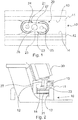
- Fig. 2 shows a cross-sectional view of a first embodiment of the device according to the invention.
- the door element 30, in particular a sliding door for a passenger transport vehicle, is connected to the connecting element 23 via an elastic bearing element 27.
- the elastic bearing element 27 may for example be designed as a spring.
- the door element 30 can be brought outside the area bounded by the guide profile 10 in order, for example, to cause a deliberate contact of the door element 30 outside the guide profile 10. Due to the elastic mounting of the rocker 23, the door element 30 can thus be moved transversely to the guide profile 10 when it is exposed to an externally applied force.
- the elastic bearing element 27 can produce a sealing connection with a sealing element 15 arranged in a leg 11 of the guide profile 10, for example in the closed state of the door element.
Landscapes
- Engineering & Computer Science (AREA)
- Mechanical Engineering (AREA)
- Support Devices For Sliding Doors (AREA)
- Window Of Vehicle (AREA)
- Registering, Tensioning, Guiding Webs, And Rollers Therefor (AREA)
- Illuminated Signs And Luminous Advertising (AREA)
Abstract
Description
- Die vorliegende Anmeldung betrifft eine Vorrichtung zur Führung eines Türelements, insbesondere einer Schiebetür für ein Personenbeförderungsfahrzeug beispielsweise für Busse oder Schienenfahrzeuge des öffentlichen Nahverkehrs.
- Derartige Vorrichtungen sind aus dem Stand der Technik bekannt.
- Bei dieser Art von Fahrzeugen wird aufgrund der vorliegenden Einbaugegebenheiten die Führung der Türelemente einachsig ausgeführt. Hierzu werden beispielsweise Laufrollen, welche mittels geeigneter Lagerelemente an dem Türelement befestigt sind, in einachsigen Führungsprofilen geführt. Im täglichen Fahrbetrieb sind die Türelemente aufgrund von Straßenunebenheit oder den Unebenheiten bei den Schienenanlagen ständigen Bewegungen ausgesetzt. Da die Bewegungen sich auf die Führungsprofile übertragen, sind diese im Fahrbetrieb hohen Kräften ausgesetzt. Um dem entgegenzuwirken, müssen diese kompensiert werden. Zudem ist bei einer starren Verbindung zwischen dem Türelement und der Laufrolle eine hohe Genauigkeit des Führungsprofils erforderlich, da die Laufrollen auf dauerhafte Anlage bei der Montage eingestellt werden.
- Weiterhin sind Vorrichtungen bekannt, bei denen die Lagerung bei größeren auftretenden Bewegungen in einer Richtung elastisch ausgeführt wird. Bei einer Umsetzung mit zwei Rollen dient beispielsweise die elastisch gelagerte Rolle als sogenannte Anpressrolle und die fest gelagerte Rolle als Führungsrolle.
- Der Erfindung liegt die Aufgabe zu Grunde eine gegenüber dem Stand der Technik verbesserte Vorrichtung zur Führung eines Türelements, insbesondere einer Schiebetür für ein Personenbeförderungsfahrzeug bereitzustellen. Insbesondere hat sich die Erfindung zum Ziel gemacht, eine Vorrichtung zur Führung eines Türelements bereitzustellen, die zuverlässig funktioniert und einen relativ geringen Wartungsaufwand aufweist.
- Gelöst wird diese Aufgabe durch eine Vorrichtung mit den Merkmalen des Patentanspruchs 1. Vorteilhafte Ausgestaltungen und Varianten der Erfindung ergeben sich aus den abhängigen Ansprüchen und der nachfolgenden Beschreibung.
- Erfindungsgemäß ist vorgesehen, dass die Vorrichtung zur Führung eines Türelements, insbesondere einer Schiebetür für ein Personenbeförderungsfahrzeug ein Führungsprofil zur Führung des Türelements enthält, wobei das Türelement über mindestens ein elastisches Lagerelement elastisch mit mindestens einem Laufrollenpaar verbunden ist, so dass das Türelement bei einer Krafteinwirkung quer zur seiner Längsachse bewegbar ist.
- Hierdurch wird eine elastische Führung des Türelements, insbesondere einer Schiebetür für ein Personenbeförderungsfahrzeug erreicht. Durch die elastische Ausführung werden die Kräfte, denen die Türelemente im täglichen Fahrbetrieb ausgesetzt sind besser absorbiert. Ferner können die Führungsprofile größere Fehlertoleranzen aufweisen, da eventuell vorhandene Unebenheiten durch die elastische Ausgestaltung ausgeglichen werden.
- Dadurch, dass das Türelement bei einer Krafteinwirkung, beispielsweise einer von außen auftretenden Kraft, quer zur seiner Längsachse bewegbar ist, wird ermöglicht, dass das Türelement außerhalb eines durch das Führungsprofil begrenzten Bereichs gebracht werden kann. So ist beispielsweise möglich ein gewünschtes Anliegen des Türelements außerhalb des Führungsprofils zu bewirken.
- Gemäß einer bevorzugten Ausführungsvariante ist eine erste Laufrolle des Laufrollenpaars über ein erstes elastisches Lagerelement und eine zweite Laufrolle des Laufrollenpaars über ein zweites elastisches Lagerelement mit dem Türelement elastisch verbunden. Bei dieser Ausführung ist das Türelement über mindestens zwei elastische Lagerelemente elastisch mit mindestens einem Laufrollenpaar verbunden.
- Vorzugsweise handelt es sich beim dem Lagerelement um eine Feder, die das Türelement mit der jeweiligen Laufrolle verbindet und diese jeweils an das Führungsprofil drückt. Die Federsteifigkeiten mit welcher die beiden Laufrollen an das Führungsprofil gedrückt werden, bestimmen dabei die Führungslinien. Beispielsweise entspricht eine gleiche Federkennlinie einer mittigen Führung des Türelements innerhalb des Führungsprofils.
- Gemäß einer anderen bevorzugten Ausführungsvariante sind beide Laufrollen des Laufrollenpaars über ein drehbares Verbindungselement miteinander verbunden, wobei das drehbare Verbindungselement wiederum über mindestens eins, mehr bevorzugt zwei elastische Lagerelemente, elastisch mit dem Türelement verbunden ist. Die elastischen Lagerelemente können vorzugsweise aus einem Metall und/oder einem elastischen Kunststoff ausgebildet sein. So können die elastischen Lagerelemente beispielsweise als Metallfedern ausgeführt sein. Vorzugsweise ist der elastische Kunststoff ausgewählt aus der Gruppe der Elastomere, Thermoplaste oder thermoelastischen Elastomere. Weiterhin können die elastischen Lagerelemente vorzugsweise aus einem Verbundmaterial ausgebildet sein.
- Dabei sind die Laufrollen vorzugsweise im Bereich der jeweiligen Enden des Verbindungselements angeordnet und mittels geeigneter Mittel, beispielsweise Drehbolzen, mit dem Verbindungselement drehbar verbunden.
- Je nach Ausführungsform gilt, dass sofern ein Laufrollenpaar vorgesehen ist, dieses vorzugsweise mittig auf einer, vorzugsweise unteren Stirnseite des Türelements angeordnet ist. Vorzugsweise weist das Türelement zwei, mehr bevorzugt drei Laufrollenpaare auf. Bei einer Ausführung mit zwei Laufrollenpaaren sind diese jeweils im Bereich der distalen Enden der Stirnseite des Türelements, bei einer Ausführung mit drei Laufrollenpaaren ist zudem eines mittig angeordnet.
- Das Verbindungselement ist vorzugsweise als Wippe ausgeführt.
- In einer weiteren bevorzugten Ausführungsvariante weist das Verbindungselement mittig zwischen der ersten und der zweiten Laufrolle einen Drehpunkt auf, über den die Führung des Laufrollenpaars gesteuert werden kann.
- Sofern der Drehpunkt mittig zwischen den beiden Laufrollen liegt, resultiert hierdurch eine zentrische Führung des Laufrollenpaars. Bei einer zentrischen Führung des Laufrollenpaars werden die Laufrollen jeweils an die sich gegenüberliegenden Anlageflächen des Führungsprofils gedrückt und entlang dieser längs zur Längsachse des Führungsprofils geführt. Der Drehpunkt folgt somit einer zentralen Verlaufslinie innerhalb des Führungsprofils. Bei einer zentralen Führung werden die Laufrollen somit versetzt zueinander geführt. Durch Verändern des Drehpunktes zwischen den beiden Laufrollen kann die Führung auch außerzentrisch an einer definieren Linie liegen. Beispielsweise können bei einer derartigen außerzentrischen Führung beide Laufrollen an eine der beiden Anlageflächen gedrückt und entlang dieser geführt werden. In diesem Fall werden die Laufrollen nicht zueinander versetzt, sondern in einer Linie geführt.
- In einer vorteilhaften Ausgestaltung sind die Laufrollen des Laufrollenpaars innerhalb des Führungsprofils zueinander versetzt angeordnet. Die Verlaufslinien der beiden Laufrollen sind demnach parallel zueinander im außerzentrischen Bereich des Führungsprofils.
- Vorzugsweise weist das Führungsprofil einen ersten und einen zweiten Schenkel auf, so dass es im Wesentlichen U-förmig ausgebildet ist. Hierdurch entsteht innerhalb des Führungsprofils ein Führungskanal, in dem das Laufrollenpaar geführt werden kann.
- Vorzugsweise ist das Führungsprofil einläufig ausgeführt, so dass wenig Bauraum für die erfindungsgemäße Vorrichtung verbraucht wird.
- In einer besonders bevorzugten Ausführungsvariante ist der Abstand zwischen der ersten und der zweiten Anlagefläche größer als der Durchmesser der Laufrollen, so dass hierdurch in Kombination mit dem jeweiligen Drehpunkt des Verbindungselements unterschiedliche Führungen des Laufrollenpaars realisiert werden können.
- In einer weiteren besonders bevorzugten Ausführungsvariante weist das Führungsprofil an einem seiner Schenkel ein Dichtungselement auf. Durch die Möglichkeit einer Querbewegung des Türelements kann das elastische Lagerelement mit dem Dichtungselement eine dichtende Verbindung, beispielsweise im geschlossenen Zustand erzeugen.
- Im Folgenden wird die Erfindung anhand von Zeichnungen näher erläutert. Im Einzelnen zeigen:
-
Fig. 1 eine Darstellung einer ersten Ausführungsform eines Teils der erfindungsgemäßen Vorrichtung, und -
Fig. 2 eine Querschnittsdarstellung einer ersten Ausführungsform der erfindungsgemäßen Vorrichtung. -
Fig. 1 zeigt eine Darstellung einer ersten Ausführungsform eines Teils der erfindungsgemäßen Vorrichtung. - Gezeigt ist ein einläufiges Führungsprofil 10 mit einem ersten und einem zweiten Schenkel 11, 12. Die Schenkel 11, 12 bilden innenseitig eine erste und eine zweite Anlagefläche 13, 14 an die eine erste und eine zweite Laufrolle 21, 22 eines Laufrollenpaars 20 gedrückt und entlang dieser längs zur Längsachse des Führungsprofils 10 geführt werden. Der zwischen der ersten und der zweiten Anlagefläche 13, 14 gebildete Abstand ist hierbei größer als der Durchmesser der jeweiligen Laufrollen 21, 22.
- Die Laufrollen 21, 22 des Laufrollenpaars 20 sind über ein drehbares Verbindungselement 23, beispielsweise eine Wippe, miteinander verbunden. Wie der Darstellung zu entnehmen ist, sind die Laufrollen 21, 22 im Bereich der jeweiligen Enden des Verbindungselements 23 bzw. der Wippe angeordnet und mittels geeigneter Drehelemente 24, 25, beispielsweise Drehbolzen, mit dem Verbindungselement 23 bzw. der Wippe drehbar verbunden. Weiterhin weist das Verbindungselement 23 bzw. die Wippe, einen Drehpunkt 26 auf. In der in
Fig. 1 gezeigter Darstellung liegt der Drehpunkt 26 mittig zwischen den beiden Laufrollen 21, 22, so dass hierdurch eine zentrische Führung des Laufrollenpaars 20 resultiert. Bei einer zentrischen Führung des Laufrollenpaars 20 werden die Laufrollen 21, 22 jeweils an die sich gegenüberliegenden Anlageflächen 13, 14 gedrückt und entlang dieser längs zur Längsachse des Führungsprofils geführt. Der Drehpunkt 26 der Wippe 23 folgt somit einer zentralen Verlaufslinie innerhalb des Führungsprofils 10. Dadurch werden die Laufrollen 21, 22 des Laufrollenpaars 20 nicht auf einer Linie sondern versetzt zueinander geführt. Durch Verändern des Drehpunktes 26 zwischen den beiden Laufrollen 21, 22 kann die Führung auch außerzentrisch an einer definieren Linie liegen. Beispielsweise können bei einer derartigen außerzentrischen Führung beide Laufrollen 21, 22 an eine der beiden Anlageflächen 13, 14 gedrückt und entlang dieser geführt werden. In diesem Fall werden die Laufrollen 21, 22 nicht zueinander versetzt sondern in einer Linie geführt. - Weiterhin ist an dem Verbindungselement 23 ein elastisches Lagerelement 27 mittig angeordnet, das mit dem Türelement 30 elastisch verbunden ist.
-
Fig. 2 zeigt eine Querschnittsdarstellung einer ersten Ausführungsform der erfindungsgemäßen Vorrichtung. Das Türelement 30, insbesondere eine Schiebetür für ein Personenbeförderungsfahrzeug ist über ein elastisches Lagerelement 27 mit dem Verbindungselement 23 verbunden. Das elastische Lagerelement 27 kann beispielsweise als Feder ausgeführt sein. Durch die elastische Lagerung des Verbindungselements 23 bzw. der Wippe kann das Türelement 30 außerhalb des durch das Führungsprofil 10 begrenzten Bereichs gebracht werden, um beispielsweise ein bewusstes Anliegen des Türelements 30 außerhalb des Führungsprofils 10 hervorzurufen. Durch die elastische Lagerung der Wippe 23 kann das Türelement 30 somit quer zum Führungsprofil 10 bewegt werden, wenn es einer von außen eingebrachten Kraft ausgesetzt wird. Infolge der Querbewegung kann das elastische Lagerelement 27 mit einem in einem Schenkel 11 des Führungsprofils 10 angeordnetem Dichtungselement 15 eine dichtende Verbindung, beispielsweise im geschlossenen Zustand des Türelements erzeugen. -
- 10
- Führungsprofil
- 11
- erster Schenkel
- 12
- zweiter Schenkel
- 13
- erste Anlagefläche
- 14
- zweite Anlagefläche
- 15
- Dichtungselement
- 20
- Laufrollenpaar
- 21
- erste Laufrolle
- 22
- zweite Laufrolle
- 23
- Verbindungselement
- 24
- erstes Drehelement
- 25
- zweites Drehelement
- 26
- Drehpunkt
- 27
- elastisches Lagerelement
- 30
- Türelement
Claims (10)
- Vorrichtung zur Führung eines Türelements (30), insbesondere einer Schiebetür für ein Personenbeförderungsfahrzeug enthaltend ein Führungsprofil (10) zur Führung des Türelements (30),
dadurch gekennzeichnet, dass
das Türelement (30) über mindestens ein elastisches Lagerelement (27) elastisch mit mindestens einem Laufrollenpaar (20) verbunden ist, so dass das Türelement (30) bei einer Krafteinwirkung quer zur seiner Längsachse bewegbar ist. - Vorrichtung nach Anspruch 1, wobei eine erste Laufrolle (21) des Laufrollenpaars (20) über ein erstes elastisches Lagerelement und eine zweite Laufrolle (22) des Laufrollenpaars (20) über ein zweites elastisches Lagerelement mit dem Türelement (30) elastisch verbunden ist.
- Vorrichtung nach Anspruch 1, wobei beide Laufrollen (21, 22) des Laufrollenpaars (20) über ein drehbares Verbindungselement (23) verbunden sind, welches über das elastische Lagerelement (27) elastisch mit dem Türelement (30) verbunden ist.
- Vorrichtung nach Anspruch 3, wobei das Verbindungselement (27) als Wippe ausgeführt ist.
- Vorrichtung nach Anspruch 3 oder 4, wobei das Verbindungselement (27) mittig zwischen der ersten und der zweiten Laufrolle (21, 22) einen Drehpunkt (26) aufweist.
- Vorrichtung nach einem der vorhergehenden Ansprüche 1 bis 5, wobei die Laufrollen (21, 22) des Laufrollenpaars (20) zueinander versetzt angeordnet sind.
- Vorrichtung nach einem der vorhergehenden Ansprüche 1 bis 6, wobei das Führungsprofil (10) einen ersten und einen zweiten Schenkel (11, 12) aufweist, so dass es U-förmig ausgebildet ist.
- Vorrichtung nach einem der vorhergehenden Ansprüche 1 bis 7, wobei das Führungsprofil (10) einläufig ausgeführt ist.
- Vorrichtung nach einem der vorhergehenden Ansprüche 1 bis 8, wobei der Abstand zwischen einer ersten und einer zweiten Anlagefläche 13, 14 des Führungsprofils (10) größer ist als der Durchmesser der Laufrollen (21, 22).
- Vorrichtung nach einem der vorhergehenden Ansprüche 1 bis 9, wobei das Führungsprofil (10) an einem seiner Schenkel (11) ein Dichtungselement (15) aufweist.
Applications Claiming Priority (2)
| Application Number | Priority Date | Filing Date | Title |
|---|---|---|---|
| DE102016111066 | 2016-06-16 | ||
| DE202017101297.2U DE202017101297U1 (de) | 2016-06-16 | 2017-03-07 | Führung durch mehrfach elastische Lagerung |
Publications (2)
| Publication Number | Publication Date |
|---|---|
| EP3258043A1 true EP3258043A1 (de) | 2017-12-20 |
| EP3258043B1 EP3258043B1 (de) | 2022-06-08 |
Family
ID=58694306
Family Applications (1)
| Application Number | Title | Priority Date | Filing Date |
|---|---|---|---|
| EP17175362.7A Active EP3258043B1 (de) | 2016-06-16 | 2017-06-09 | Vorrichtung zur führung eines türelements mit elastischer lagerung |
Country Status (4)
| Country | Link |
|---|---|
| EP (1) | EP3258043B1 (de) |
| DE (1) | DE202017101297U1 (de) |
| ES (1) | ES2925869T3 (de) |
| PL (1) | PL3258043T3 (de) |
Cited By (1)
| Publication number | Priority date | Publication date | Assignee | Title |
|---|---|---|---|---|
| EP3859108A1 (de) * | 2020-01-31 | 2021-08-04 | Ningbo Geely Automobile Research & Development Co. Ltd. | Rollenanordnung für eine schiebetür eines fahrzeugs |
Citations (3)
| Publication number | Priority date | Publication date | Assignee | Title |
|---|---|---|---|---|
| DE19954111A1 (de) * | 1999-11-11 | 2001-05-23 | Alber Gmbh | Schiebetürführung |
| DE102007038842A1 (de) * | 2007-08-16 | 2009-02-19 | Dorma Gmbh + Co. Kg | Schiebetüraufhängung |
| JP2009155792A (ja) * | 2007-12-25 | 2009-07-16 | Panasonic Electric Works Co Ltd | 走行ガイド装置およびそれを備えた引き戸 |
-
2017
- 2017-03-07 DE DE202017101297.2U patent/DE202017101297U1/de not_active Expired - Lifetime
- 2017-06-09 PL PL17175362.7T patent/PL3258043T3/pl unknown
- 2017-06-09 EP EP17175362.7A patent/EP3258043B1/de active Active
- 2017-06-09 ES ES17175362T patent/ES2925869T3/es active Active
Patent Citations (3)
| Publication number | Priority date | Publication date | Assignee | Title |
|---|---|---|---|---|
| DE19954111A1 (de) * | 1999-11-11 | 2001-05-23 | Alber Gmbh | Schiebetürführung |
| DE102007038842A1 (de) * | 2007-08-16 | 2009-02-19 | Dorma Gmbh + Co. Kg | Schiebetüraufhängung |
| JP2009155792A (ja) * | 2007-12-25 | 2009-07-16 | Panasonic Electric Works Co Ltd | 走行ガイド装置およびそれを備えた引き戸 |
Cited By (4)
| Publication number | Priority date | Publication date | Assignee | Title |
|---|---|---|---|---|
| EP3859108A1 (de) * | 2020-01-31 | 2021-08-04 | Ningbo Geely Automobile Research & Development Co. Ltd. | Rollenanordnung für eine schiebetür eines fahrzeugs |
| CN115003530A (zh) * | 2020-01-31 | 2022-09-02 | 宁波吉利汽车研究开发有限公司 | 用于滑动式车门的滚子组件 |
| CN115003530B (zh) * | 2020-01-31 | 2023-12-05 | 宁波吉利汽车研究开发有限公司 | 用于滑动式车门的滚子组件 |
| US12291908B2 (en) | 2020-01-31 | 2025-05-06 | Ningbo Geely Automobile Research & Dev. Co., Ltd. | Roller assembly for a sliding vehicle door |
Also Published As
| Publication number | Publication date |
|---|---|
| ES2925869T3 (es) | 2022-10-20 |
| DE202017101297U1 (de) | 2017-04-20 |
| EP3258043B1 (de) | 2022-06-08 |
| PL3258043T3 (pl) | 2022-09-26 |
Similar Documents
| Publication | Publication Date | Title |
|---|---|---|
| DE10145896B4 (de) | Verschiebeeinrichtung für eine Fahrzeuglenksäule | |
| DE10139631B4 (de) | Längseinstellvorrichtung für einen Fahrzeugsitz | |
| DE202004021803U1 (de) | Führungssystem für eine Schiebetür | |
| DE112018000009B4 (de) | Längseinsteller für einen Fahrzeugsitz und Fahrzeugsitz | |
| DE102015219472A1 (de) | Längsverstellvorrichtung für einen Fahrzeugsitz | |
| DE102009052352A1 (de) | Wellenlageranordnung | |
| EP2290672B1 (de) | Kontaktanordnung für elektromechanische Hilfsschalter | |
| DE102008057148B4 (de) | Bahn-Kippschalter | |
| DE102005014745A1 (de) | Gerade Führung und untere Abdichtung | |
| EP3258043B1 (de) | Vorrichtung zur führung eines türelements mit elastischer lagerung | |
| DE102009045653B4 (de) | Schiene einer Längsführung mit einem Lagerbock und einer schwenkbaren Klappe | |
| DE10008523B4 (de) | System zur kontinuierlichen Energieaufnahme durch Relativverschiebung | |
| DE102009055662B3 (de) | Brennstoffzellenanordnung | |
| DE102006007978A1 (de) | Teleskopführung mit Rastelement | |
| DE19949647A1 (de) | Türscharnier | |
| DE3502864A1 (de) | Vorrichtung zur stumpfen elektrischen verbindung von stromschienen | |
| EP1805048A1 (de) | Führungsvorrichtung für ein bewegbares dachelement eines öffnungsfähigen fahrzeugdaches | |
| EP3471982B1 (de) | Dreipunktlagerung einer schiebetür | |
| DE2260187A1 (de) | Bremsbetaetigungsvorrichtung, insbesondere fuer trommelbremsen | |
| DE602004010789T2 (de) | Türanordnung | |
| EP4224037B1 (de) | Kugelgewindetrieb, insbesondere für eine kraftfahrzeuglenkung, und kraftfahrzeuglenkung | |
| DE102010039605B4 (de) | Geschlitzte Zahnstange zur Reduzierung der Federrate | |
| DE102006054924A1 (de) | Laufwagenanordnung zur Schiebeführung von Türen | |
| DE19630724C2 (de) | Montagewerkzeug | |
| DE3400146C2 (de) | Klammer zum Fixieren zweier über eine Aufnahmeöffnung ineinanderschiebbarer Bauteile |
Legal Events
| Date | Code | Title | Description |
|---|---|---|---|
| PUAI | Public reference made under article 153(3) epc to a published international application that has entered the european phase |
Free format text: ORIGINAL CODE: 0009012 |
|
| STAA | Information on the status of an ep patent application or granted ep patent |
Free format text: STATUS: THE APPLICATION HAS BEEN PUBLISHED |
|
| AK | Designated contracting states |
Kind code of ref document: A1 Designated state(s): AL AT BE BG CH CY CZ DE DK EE ES FI FR GB GR HR HU IE IS IT LI LT LU LV MC MK MT NL NO PL PT RO RS SE SI SK SM TR |
|
| AX | Request for extension of the european patent |
Extension state: BA ME |
|
| STAA | Information on the status of an ep patent application or granted ep patent |
Free format text: STATUS: REQUEST FOR EXAMINATION WAS MADE |
|
| 17P | Request for examination filed |
Effective date: 20180618 |
|
| RBV | Designated contracting states (corrected) |
Designated state(s): AL AT BE BG CH CY CZ DE DK EE ES FI FR GB GR HR HU IE IS IT LI LT LU LV MC MK MT NL NO PL PT RO RS SE SI SK SM TR |
|
| STAA | Information on the status of an ep patent application or granted ep patent |
Free format text: STATUS: EXAMINATION IS IN PROGRESS |
|
| 17Q | First examination report despatched |
Effective date: 20191217 |
|
| GRAP | Despatch of communication of intention to grant a patent |
Free format text: ORIGINAL CODE: EPIDOSNIGR1 |
|
| STAA | Information on the status of an ep patent application or granted ep patent |
Free format text: STATUS: GRANT OF PATENT IS INTENDED |
|
| INTG | Intention to grant announced |
Effective date: 20220216 |
|
| RAP3 | Party data changed (applicant data changed or rights of an application transferred) |
Owner name: BODE - DIE TUER GMBH |
|
| GRAS | Grant fee paid |
Free format text: ORIGINAL CODE: EPIDOSNIGR3 |
|
| GRAA | (expected) grant |
Free format text: ORIGINAL CODE: 0009210 |
|
| STAA | Information on the status of an ep patent application or granted ep patent |
Free format text: STATUS: THE PATENT HAS BEEN GRANTED |
|
| AK | Designated contracting states |
Kind code of ref document: B1 Designated state(s): AL AT BE BG CH CY CZ DE DK EE ES FI FR GB GR HR HU IE IS IT LI LT LU LV MC MK MT NL NO PL PT RO RS SE SI SK SM TR |
|
| REG | Reference to a national code |
Ref country code: AT Ref legal event code: REF Ref document number: 1497035 Country of ref document: AT Kind code of ref document: T Effective date: 20220615 Ref country code: CH Ref legal event code: EP |
|
| REG | Reference to a national code |
Ref country code: DE Ref legal event code: R096 Ref document number: 502017013269 Country of ref document: DE |
|
| REG | Reference to a national code |
Ref country code: IE Ref legal event code: FG4D Free format text: LANGUAGE OF EP DOCUMENT: GERMAN |
|
| PGFP | Annual fee paid to national office [announced via postgrant information from national office to epo] |
Ref country code: DE Payment date: 20220621 Year of fee payment: 6 |
|
| REG | Reference to a national code |
Ref country code: NL Ref legal event code: FP |
|
| REG | Reference to a national code |
Ref country code: FI Ref legal event code: FGE |
|
| REG | Reference to a national code |
Ref country code: LT Ref legal event code: MG9D |
|
| PGFP | Annual fee paid to national office [announced via postgrant information from national office to epo] |
Ref country code: NL Payment date: 20220727 Year of fee payment: 6 |
|
| REG | Reference to a national code |
Ref country code: ES Ref legal event code: FG2A Ref document number: 2925869 Country of ref document: ES Kind code of ref document: T3 Effective date: 20221020 |
|
| PG25 | Lapsed in a contracting state [announced via postgrant information from national office to epo] |
Ref country code: SE Free format text: LAPSE BECAUSE OF FAILURE TO SUBMIT A TRANSLATION OF THE DESCRIPTION OR TO PAY THE FEE WITHIN THE PRESCRIBED TIME-LIMIT Effective date: 20220608 Ref country code: NO Free format text: LAPSE BECAUSE OF FAILURE TO SUBMIT A TRANSLATION OF THE DESCRIPTION OR TO PAY THE FEE WITHIN THE PRESCRIBED TIME-LIMIT Effective date: 20220908 Ref country code: LT Free format text: LAPSE BECAUSE OF FAILURE TO SUBMIT A TRANSLATION OF THE DESCRIPTION OR TO PAY THE FEE WITHIN THE PRESCRIBED TIME-LIMIT Effective date: 20220608 Ref country code: HR Free format text: LAPSE BECAUSE OF FAILURE TO SUBMIT A TRANSLATION OF THE DESCRIPTION OR TO PAY THE FEE WITHIN THE PRESCRIBED TIME-LIMIT Effective date: 20220608 Ref country code: GR Free format text: LAPSE BECAUSE OF FAILURE TO SUBMIT A TRANSLATION OF THE DESCRIPTION OR TO PAY THE FEE WITHIN THE PRESCRIBED TIME-LIMIT Effective date: 20220909 Ref country code: BG Free format text: LAPSE BECAUSE OF FAILURE TO SUBMIT A TRANSLATION OF THE DESCRIPTION OR TO PAY THE FEE WITHIN THE PRESCRIBED TIME-LIMIT Effective date: 20220908 |
|
| PGFP | Annual fee paid to national office [announced via postgrant information from national office to epo] |
Ref country code: TR Payment date: 20220826 Year of fee payment: 6 Ref country code: IT Payment date: 20220826 Year of fee payment: 6 Ref country code: GB Payment date: 20220726 Year of fee payment: 6 Ref country code: FI Payment date: 20220722 Year of fee payment: 6 Ref country code: ES Payment date: 20220729 Year of fee payment: 6 Ref country code: CZ Payment date: 20220728 Year of fee payment: 6 Ref country code: AT Payment date: 20220721 Year of fee payment: 6 |
|
| PG25 | Lapsed in a contracting state [announced via postgrant information from national office to epo] |
Ref country code: RS Free format text: LAPSE BECAUSE OF FAILURE TO SUBMIT A TRANSLATION OF THE DESCRIPTION OR TO PAY THE FEE WITHIN THE PRESCRIBED TIME-LIMIT Effective date: 20220608 Ref country code: LV Free format text: LAPSE BECAUSE OF FAILURE TO SUBMIT A TRANSLATION OF THE DESCRIPTION OR TO PAY THE FEE WITHIN THE PRESCRIBED TIME-LIMIT Effective date: 20220608 |
|
| PGFP | Annual fee paid to national office [announced via postgrant information from national office to epo] |
Ref country code: PL Payment date: 20220718 Year of fee payment: 6 Ref country code: FR Payment date: 20220729 Year of fee payment: 6 |
|
| PGFP | Annual fee paid to national office [announced via postgrant information from national office to epo] |
Ref country code: CH Payment date: 20220728 Year of fee payment: 6 |
|
| PG25 | Lapsed in a contracting state [announced via postgrant information from national office to epo] |
Ref country code: SM Free format text: LAPSE BECAUSE OF FAILURE TO SUBMIT A TRANSLATION OF THE DESCRIPTION OR TO PAY THE FEE WITHIN THE PRESCRIBED TIME-LIMIT Effective date: 20220608 Ref country code: SK Free format text: LAPSE BECAUSE OF FAILURE TO SUBMIT A TRANSLATION OF THE DESCRIPTION OR TO PAY THE FEE WITHIN THE PRESCRIBED TIME-LIMIT Effective date: 20220608 Ref country code: RO Free format text: LAPSE BECAUSE OF FAILURE TO SUBMIT A TRANSLATION OF THE DESCRIPTION OR TO PAY THE FEE WITHIN THE PRESCRIBED TIME-LIMIT Effective date: 20220608 Ref country code: PT Free format text: LAPSE BECAUSE OF FAILURE TO SUBMIT A TRANSLATION OF THE DESCRIPTION OR TO PAY THE FEE WITHIN THE PRESCRIBED TIME-LIMIT Effective date: 20221010 Ref country code: EE Free format text: LAPSE BECAUSE OF FAILURE TO SUBMIT A TRANSLATION OF THE DESCRIPTION OR TO PAY THE FEE WITHIN THE PRESCRIBED TIME-LIMIT Effective date: 20220608 |
|
| REG | Reference to a national code |
Ref country code: BE Ref legal event code: MM Effective date: 20220630 |
|
| PG25 | Lapsed in a contracting state [announced via postgrant information from national office to epo] |
Ref country code: IS Free format text: LAPSE BECAUSE OF FAILURE TO SUBMIT A TRANSLATION OF THE DESCRIPTION OR TO PAY THE FEE WITHIN THE PRESCRIBED TIME-LIMIT Effective date: 20221008 |
|
| REG | Reference to a national code |
Ref country code: DE Ref legal event code: R097 Ref document number: 502017013269 Country of ref document: DE |
|
| PG25 | Lapsed in a contracting state [announced via postgrant information from national office to epo] |
Ref country code: MC Free format text: LAPSE BECAUSE OF FAILURE TO SUBMIT A TRANSLATION OF THE DESCRIPTION OR TO PAY THE FEE WITHIN THE PRESCRIBED TIME-LIMIT Effective date: 20220608 Ref country code: AL Free format text: LAPSE BECAUSE OF FAILURE TO SUBMIT A TRANSLATION OF THE DESCRIPTION OR TO PAY THE FEE WITHIN THE PRESCRIBED TIME-LIMIT Effective date: 20220608 |
|
| PLBE | No opposition filed within time limit |
Free format text: ORIGINAL CODE: 0009261 |
|
| STAA | Information on the status of an ep patent application or granted ep patent |
Free format text: STATUS: NO OPPOSITION FILED WITHIN TIME LIMIT |
|
| PG25 | Lapsed in a contracting state [announced via postgrant information from national office to epo] |
Ref country code: LU Free format text: LAPSE BECAUSE OF NON-PAYMENT OF DUE FEES Effective date: 20220609 Ref country code: IE Free format text: LAPSE BECAUSE OF NON-PAYMENT OF DUE FEES Effective date: 20220609 Ref country code: DK Free format text: LAPSE BECAUSE OF FAILURE TO SUBMIT A TRANSLATION OF THE DESCRIPTION OR TO PAY THE FEE WITHIN THE PRESCRIBED TIME-LIMIT Effective date: 20220608 |
|
| 26N | No opposition filed |
Effective date: 20230310 |
|
| PG25 | Lapsed in a contracting state [announced via postgrant information from national office to epo] |
Ref country code: SI Free format text: LAPSE BECAUSE OF FAILURE TO SUBMIT A TRANSLATION OF THE DESCRIPTION OR TO PAY THE FEE WITHIN THE PRESCRIBED TIME-LIMIT Effective date: 20220608 Ref country code: BE Free format text: LAPSE BECAUSE OF NON-PAYMENT OF DUE FEES Effective date: 20220630 |
|
| REG | Reference to a national code |
Ref country code: DE Ref legal event code: R119 Ref document number: 502017013269 Country of ref document: DE |
|
| PG25 | Lapsed in a contracting state [announced via postgrant information from national office to epo] |
Ref country code: FI Free format text: LAPSE BECAUSE OF NON-PAYMENT OF DUE FEES Effective date: 20230609 Ref country code: CZ Free format text: LAPSE BECAUSE OF NON-PAYMENT OF DUE FEES Effective date: 20230609 |
|
| REG | Reference to a national code |
Ref country code: CH Ref legal event code: PL |
|
| REG | Reference to a national code |
Ref country code: NL Ref legal event code: MM Effective date: 20230701 |
|
| REG | Reference to a national code |
Ref country code: AT Ref legal event code: MM01 Ref document number: 1497035 Country of ref document: AT Kind code of ref document: T Effective date: 20230609 |
|
| GBPC | Gb: european patent ceased through non-payment of renewal fee |
Effective date: 20230609 |
|
| PG25 | Lapsed in a contracting state [announced via postgrant information from national office to epo] |
Ref country code: NL Free format text: LAPSE BECAUSE OF NON-PAYMENT OF DUE FEES Effective date: 20230701 Ref country code: HU Free format text: LAPSE BECAUSE OF FAILURE TO SUBMIT A TRANSLATION OF THE DESCRIPTION OR TO PAY THE FEE WITHIN THE PRESCRIBED TIME-LIMIT; INVALID AB INITIO Effective date: 20170609 |
|
| PG25 | Lapsed in a contracting state [announced via postgrant information from national office to epo] |
Ref country code: AT Free format text: LAPSE BECAUSE OF NON-PAYMENT OF DUE FEES Effective date: 20230609 |
|
| PG25 | Lapsed in a contracting state [announced via postgrant information from national office to epo] |
Ref country code: MK Free format text: LAPSE BECAUSE OF FAILURE TO SUBMIT A TRANSLATION OF THE DESCRIPTION OR TO PAY THE FEE WITHIN THE PRESCRIBED TIME-LIMIT Effective date: 20220608 Ref country code: CY Free format text: LAPSE BECAUSE OF FAILURE TO SUBMIT A TRANSLATION OF THE DESCRIPTION OR TO PAY THE FEE WITHIN THE PRESCRIBED TIME-LIMIT Effective date: 20220608 Ref country code: AT Free format text: LAPSE BECAUSE OF NON-PAYMENT OF DUE FEES Effective date: 20230609 Ref country code: DE Free format text: LAPSE BECAUSE OF NON-PAYMENT OF DUE FEES Effective date: 20240103 Ref country code: GB Free format text: LAPSE BECAUSE OF NON-PAYMENT OF DUE FEES Effective date: 20230609 Ref country code: CH Free format text: LAPSE BECAUSE OF NON-PAYMENT OF DUE FEES Effective date: 20230630 |
|
| PG25 | Lapsed in a contracting state [announced via postgrant information from national office to epo] |
Ref country code: FR Free format text: LAPSE BECAUSE OF NON-PAYMENT OF DUE FEES Effective date: 20230630 |
|
| REG | Reference to a national code |
Ref country code: ES Ref legal event code: FD2A Effective date: 20240729 |
|
| PG25 | Lapsed in a contracting state [announced via postgrant information from national office to epo] |
Ref country code: IT Free format text: LAPSE BECAUSE OF NON-PAYMENT OF DUE FEES Effective date: 20230609 |
|
| PG25 | Lapsed in a contracting state [announced via postgrant information from national office to epo] |
Ref country code: MT Free format text: LAPSE BECAUSE OF FAILURE TO SUBMIT A TRANSLATION OF THE DESCRIPTION OR TO PAY THE FEE WITHIN THE PRESCRIBED TIME-LIMIT Effective date: 20220608 |
|
| PG25 | Lapsed in a contracting state [announced via postgrant information from national office to epo] |
Ref country code: ES Free format text: LAPSE BECAUSE OF NON-PAYMENT OF DUE FEES Effective date: 20230610 |
|
| PG25 | Lapsed in a contracting state [announced via postgrant information from national office to epo] |
Ref country code: ES Free format text: LAPSE BECAUSE OF NON-PAYMENT OF DUE FEES Effective date: 20230610 |
|
| PG25 | Lapsed in a contracting state [announced via postgrant information from national office to epo] |
Ref country code: BG Free format text: LAPSE BECAUSE OF FAILURE TO SUBMIT A TRANSLATION OF THE DESCRIPTION OR TO PAY THE FEE WITHIN THE PRESCRIBED TIME-LIMIT Effective date: 20220608 |
|
| PG25 | Lapsed in a contracting state [announced via postgrant information from national office to epo] |
Ref country code: BG Free format text: LAPSE BECAUSE OF FAILURE TO SUBMIT A TRANSLATION OF THE DESCRIPTION OR TO PAY THE FEE WITHIN THE PRESCRIBED TIME-LIMIT Effective date: 20220608 |
|
| PG25 | Lapsed in a contracting state [announced via postgrant information from national office to epo] |
Ref country code: PL Free format text: LAPSE BECAUSE OF NON-PAYMENT OF DUE FEES Effective date: 20230609 |