EP3258182A1 - Climatiseur, procédé de commande d'arrêt et dispositif pour compresseur associé - Google Patents
Climatiseur, procédé de commande d'arrêt et dispositif pour compresseur associé Download PDFInfo
- Publication number
- EP3258182A1 EP3258182A1 EP16888598.6A EP16888598A EP3258182A1 EP 3258182 A1 EP3258182 A1 EP 3258182A1 EP 16888598 A EP16888598 A EP 16888598A EP 3258182 A1 EP3258182 A1 EP 3258182A1
- Authority
- EP
- European Patent Office
- Prior art keywords
- compressor
- rotor
- phase
- minimum load
- air conditioner
- Prior art date
- Legal status (The legal status is an assumption and is not a legal conclusion. Google has not performed a legal analysis and makes no representation as to the accuracy of the status listed.)
- Granted
Links
Images



Classifications
-
- F—MECHANICAL ENGINEERING; LIGHTING; HEATING; WEAPONS; BLASTING
- F04—POSITIVE - DISPLACEMENT MACHINES FOR LIQUIDS; PUMPS FOR LIQUIDS OR ELASTIC FLUIDS
- F04B—POSITIVE-DISPLACEMENT MACHINES FOR LIQUIDS; PUMPS
- F04B49/00—Control, e.g. of pump delivery, or pump pressure of, or safety measures for, machines, pumps, or pumping installations, not otherwise provided for, or of interest apart from, groups F04B1/00 - F04B47/00
- F04B49/02—Stopping, starting, unloading or idling control
-
- F—MECHANICAL ENGINEERING; LIGHTING; HEATING; WEAPONS; BLASTING
- F04—POSITIVE - DISPLACEMENT MACHINES FOR LIQUIDS; PUMPS FOR LIQUIDS OR ELASTIC FLUIDS
- F04B—POSITIVE-DISPLACEMENT MACHINES FOR LIQUIDS; PUMPS
- F04B49/00—Control, e.g. of pump delivery, or pump pressure of, or safety measures for, machines, pumps, or pumping installations, not otherwise provided for, or of interest apart from, groups F04B1/00 - F04B47/00
- F04B49/06—Control using electricity
-
- F—MECHANICAL ENGINEERING; LIGHTING; HEATING; WEAPONS; BLASTING
- F04—POSITIVE - DISPLACEMENT MACHINES FOR LIQUIDS; PUMPS FOR LIQUIDS OR ELASTIC FLUIDS
- F04B—POSITIVE-DISPLACEMENT MACHINES FOR LIQUIDS; PUMPS
- F04B49/00—Control, e.g. of pump delivery, or pump pressure of, or safety measures for, machines, pumps, or pumping installations, not otherwise provided for, or of interest apart from, groups F04B1/00 - F04B47/00
- F04B49/06—Control using electricity
- F04B49/065—Control using electricity and making use of computers
-
- F—MECHANICAL ENGINEERING; LIGHTING; HEATING; WEAPONS; BLASTING
- F24—HEATING; RANGES; VENTILATING
- F24F—AIR-CONDITIONING; AIR-HUMIDIFICATION; VENTILATION; USE OF AIR CURRENTS FOR SCREENING
- F24F11/00—Control or safety arrangements
-
- F—MECHANICAL ENGINEERING; LIGHTING; HEATING; WEAPONS; BLASTING
- F24—HEATING; RANGES; VENTILATING
- F24F—AIR-CONDITIONING; AIR-HUMIDIFICATION; VENTILATION; USE OF AIR CURRENTS FOR SCREENING
- F24F11/00—Control or safety arrangements
- F24F11/30—Control or safety arrangements for purposes related to the operation of the system, e.g. for safety or monitoring
-
- F—MECHANICAL ENGINEERING; LIGHTING; HEATING; WEAPONS; BLASTING
- F24—HEATING; RANGES; VENTILATING
- F24F—AIR-CONDITIONING; AIR-HUMIDIFICATION; VENTILATION; USE OF AIR CURRENTS FOR SCREENING
- F24F11/00—Control or safety arrangements
- F24F11/70—Control systems characterised by their outputs; Constructional details thereof
-
- H—ELECTRICITY
- H02—GENERATION; CONVERSION OR DISTRIBUTION OF ELECTRIC POWER
- H02P—CONTROL OR REGULATION OF ELECTRIC MOTORS, ELECTRIC GENERATORS OR DYNAMO-ELECTRIC CONVERTERS; CONTROLLING TRANSFORMERS, REACTORS OR CHOKE COILS
- H02P5/00—Arrangements specially adapted for regulating or controlling the speed or torque of two or more electric motors
- H02P5/46—Arrangements specially adapted for regulating or controlling the speed or torque of two or more electric motors for speed regulation of two or more dynamo-electric motors in relation to one another
- H02P5/50—Arrangements specially adapted for regulating or controlling the speed or torque of two or more electric motors for speed regulation of two or more dynamo-electric motors in relation to one another by comparing electrical values representing the speeds
-
- H—ELECTRICITY
- H02—GENERATION; CONVERSION OR DISTRIBUTION OF ELECTRIC POWER
- H02P—CONTROL OR REGULATION OF ELECTRIC MOTORS, ELECTRIC GENERATORS OR DYNAMO-ELECTRIC CONVERTERS; CONTROLLING TRANSFORMERS, REACTORS OR CHOKE COILS
- H02P5/00—Arrangements specially adapted for regulating or controlling the speed or torque of two or more electric motors
- H02P5/46—Arrangements specially adapted for regulating or controlling the speed or torque of two or more electric motors for speed regulation of two or more dynamo-electric motors in relation to one another
- H02P5/52—Arrangements specially adapted for regulating or controlling the speed or torque of two or more electric motors for speed regulation of two or more dynamo-electric motors in relation to one another additionally providing control of relative angular displacement
- H02P5/56—Speed and position comparison between the motors by electrical means
-
- H—ELECTRICITY
- H02—GENERATION; CONVERSION OR DISTRIBUTION OF ELECTRIC POWER
- H02P—CONTROL OR REGULATION OF ELECTRIC MOTORS, ELECTRIC GENERATORS OR DYNAMO-ELECTRIC CONVERTERS; CONTROLLING TRANSFORMERS, REACTORS OR CHOKE COILS
- H02P6/00—Arrangements for controlling synchronous motors or other dynamo-electric motors using electronic commutation dependent on the rotor position; Electronic commutators therefor
- H02P6/24—Arrangements for stopping
-
- F—MECHANICAL ENGINEERING; LIGHTING; HEATING; WEAPONS; BLASTING
- F24—HEATING; RANGES; VENTILATING
- F24F—AIR-CONDITIONING; AIR-HUMIDIFICATION; VENTILATION; USE OF AIR CURRENTS FOR SCREENING
- F24F2140/00—Control inputs relating to system states
- F24F2140/10—Pressure
- F24F2140/12—Heat-exchange fluid pressure
-
- F—MECHANICAL ENGINEERING; LIGHTING; HEATING; WEAPONS; BLASTING
- F24—HEATING; RANGES; VENTILATING
- F24F—AIR-CONDITIONING; AIR-HUMIDIFICATION; VENTILATION; USE OF AIR CURRENTS FOR SCREENING
- F24F2140/00—Control inputs relating to system states
- F24F2140/50—Load
Definitions
- the present disclosure relates to the field of air conditioner technology, and more particularly to a method for controlling a compressor in an air conditioner to stop, a device for controlling a compressor in an air conditioner to stop and an air conditioner having the device.
- a refrigerant pressure and a load are heavier when the inverter air conditioner runs at a high frequency. If a compressor of the inverter air conditioner is stopped directly at the high frequency, energy of the refrigerant pressure and of the load may be released instantly such that a vibration and stress of a piping is too large and even there is a danger to break the piping.
- it is generally to reduce the frequency to control the compressor to stop. That is, the frequency of the compressor is reduced to a low frequency and then the compressor is stopped. As a result, the vibration and stress of the piping is reduced at a moment that the compressor is stopped. However, the vibration and stress of the piping is still high at the moment that the compressor of the inverter air conditioner is stopped.
- an objective of the present disclosure is to provide a method for controlling a compressor in an air conditioner to stop.
- the method may effectively reduce a vibration and stress of a piping at a moment that the compressor is stopped.
- Another objective of the present disclosure is to provide a device for controlling a compressor in an air conditioner to stop.
- a still another objective of the present disclosure is to provide an air conditioner.
- embodiments of an aspect of the present disclosure provide a method for controlling a compressor in an air conditioner to stop.
- the method includes: acquiring a rotor phase corresponding to a minimum load of the compressor; during a shutdown process of the air conditioner, acquiring a current orientation of the rotor of the compressor and determining whether a phase of the rotor is the rotor phase corresponding to the minimum load according to the current orientation of the rotor; and controlling the compressor to stop if determining that the phase of the rotor is the rotor phase corresponding to the minimum load.
- the compressor is controlled to stop if the phase of the rotor is the rotor phase corresponding to the minimum load. Therefore, a generated vibration and stress of a piping is smaller than that generated by directly stopping the compressor, to effectively reduce the vibration and stress of the piping at the moment that the compressor is stopped and to avoid a danger of breaking the piping.
- the rotor phase corresponding to the minimum load corresponds to an orientation of the rotor when the compressor finishes exhausting within a mechanical cycle.
- the rotor phase corresponding to the minimum load is acquired according to a difference between the rotor phase corresponding to the minimum load and a mechanical zero-phase of the rotor, and according to an identification of the mechanical zero-phase.
- the rotor phase corresponding to the minimum load is acquired according to a minimum amplitude of a torque current of the compressor or by acquiring a minimum amplitude of a compensation torque of the compressor.
- inventions of another aspect of the present disclosure provide a device for controlling a compressor in an air conditioner to stop.
- the device includes: an acquiring module, configured to acquire a rotor phase corresponding to a minimum load of the compressor; a rotor orientation acquiring module, configured to acquire a current orientation of the rotor of the compressor during a shutdown process of the air conditioner; and a controlling module, configured to determine whether a phase of the rotor is the rotor phase corresponding to the minimum load according to the current orientation of the rotor, and to control the compressor to stop if determining that the phase of rotor is the rotor phase corresponding to the minimum load.
- the controlling module controls the compressor to stop if the phase of the rotor is the rotor phase corresponding to the minimum load. Therefore, a generated vibration and stress of a piping is smaller than that generated by directly stopping the compressor, to effectively reduce the vibration and stress of the piping at the moment that the compressor is stopped and to avoid a danger of breaking the piping.
- the rotor phase corresponding to the minimum load corresponds to an orientation of the rotor when the compressor finishes exhausting within a mechanical cycle.
- the acquiring module is configured to acquire the rotor phase corresponding to the minimum load according to a difference between the rotor phase corresponding to the minimum load and a mechanical zero-phase of the rotor of the compressor, and according to an identification of the mechanical zero-phase.
- the acquiring module is configured to acquire the rotor phase corresponding to the minimum load according to a minimum amplitude of a torque current of the compressor or by acquiring a minimum amplitude of a compensation torque of the compressor.
- inventions of a still another aspect of the present disclosure provide an air conditioner.
- the air conditioner includes the device for controlling a compressor in an air conditioner to stop.
- a vibration and stress of a piping may be reduced effectively at the moment that the compressor is stopped and to avoid a danger of breaking the piping.
- embodiments of a yet another aspect of the present disclosure provide another method for controlling a compressor in an air conditioner to stop.
- the other method includes: acquiring a preset phase range for stopping the compressor; during a shutdown process of the air conditioner, acquiring a current orientation of a rotor of the compressor and determining whether a phase of the rotor is within the preset phase range according to the current orientation of the rotor; and controlling the compressor to stop to reduce a vibration and stress of a piping if determining that the phase of the rotor is within the preset phase range.
- the compressor is controlled to stop if the phase of the rotor is within the preset phase range.
- a generated vibration and stress of the piping is smaller than that generated by directly stopping the compressor, to effectively reduce the vibration and stress of the piping at the moment that the compressor is stopped and to avoid a danger of breaking the piping.
- the present phase range is obtained according to an experimental test and is stored to the air condition to be invoked.
- the preset phase range is pre-determined according to a rotor phase corresponding to a minimum load of the compressor.
- embodiment of a yet another aspect of the present disclosure provide another device for controlling a compressor in an air conditioner to stop.
- the other device includes: an acquiring module, configured to acquire a preset phase range for stopping the compressor; a rotor orientation acquiring module, configured to acquire a current orientation of a rotor of the compressor during a shutdown process of the air conditioner; and a controlling module, configured to determine whether a phase of the rotor is within the preset phase range according to the current orientation of the rotor, and to control the compressor to stop to reduce a vibration and stress of a piping if determining that the phase of the rotor is within the preset phase range.
- the controlling module controls the compressor to stop if the phase of the rotor is within the preset phase range.
- the present phase range is obtained according to an experimental test and is stored to the air condition to be invoked.
- the preset phase range is pre-determined according to a rotor phase corresponding to a minimum load of the compressor.
- inventions of a yet another aspect of the present disclosure provide another air conditioner.
- the other air conditioner includes the above another device for controlling a compressor in an air conditioner to stop.
- a vibration and stress of a piping may be reduced at the moment that the compressor is stopped and to avoid a danger of breaking the piping.
- the compressor is preferably a compressor with a single rotor.
- Fig. 1 is a flow chart illustrating a method for controlling a compressor in an air conditioner to stop according to an embodiment of the present disclosure. As illustrated in Fig. 1 , the method includes followings.
- the rotor phase corresponding to the minimum load corresponds to an orientation of the rotor when a suction and an exhaust are finished, that is, an orientation of the rotor when the compressor finishes exhausting within a mechanical cycle.
- the refrigerant with a low temperature and a low pressure enters into a suction pipe of the compressor. And then the refrigerant with the low temperature and the low pressure is gradually compressed into the refrigerant with a high temperature and a high pressure.
- the refrigerant with the high temperature and the high pressure is rapidly emitted to an evaporator through an exhaust port of the compressor.
- a load pressure of the compressor is minimal after the refrigerant is released. Therefore, the rotor phase corresponding to the minimum load of the compressor is a phase of the rotor of the compressor after the refrigerant is emitted (i.e. when the compressor finishes exhausting).
- the rotor phase corresponding to the minimum load is acquired according to a difference between the rotor phase corresponding to the minimum load and a mechanical zero-phase of the rotor, and according to an identification of the mechanical zero-phase.
- the rotor phase corresponding to the minimum load is acquired according to a minimum amplitude of a torque current of the compressor or by acquiring a minimum amplitude of a compensation torque of the compressor.
- the compressor is controlled with a torque compensation using a torque compensation technique to reduce a vibration of a piping during the compressor is running.
- the amplitude of a compensation torque varies periodically with a refrigerant pressure and a load.
- the refrigerant pressure and the load are minimal, the corresponding amplitude of the compensation torque is minimal.
- the orientation of the rotor of the compressor corresponds to the rotor phase corresponding to the minimum load.
- the rotor phase corresponding to the minimum load of the compressor may be obtained directly by calibrating designed orientations of the rotor of the compressor.
- the rotor phase corresponding to the minimum load of the compressor may be obtained indirectly according to variables, such as, the amplitude of the torque current of the compressor or the amplitude of the compensation torque of the compressor.
- the rotor phase corresponding to the minimum load of the compressor may be obtained by identifying the mechanical zero-phase of the rotor of the compressor.
- the rotor phase corresponding to the minimum load of the compressor may be obtained by acquiring the minimum amplitude of the torque current or the minimum amplitude of the compensation torque.
- a current orientation of the rotor of the compressor is acquired and it is determined whether the phase of the rotor is the rotor phase corresponding to the minimum load according to the current orientation of the rotor.
- the current orientation of the rotor of the compressor may be acquired by two methods.
- One of the two methods is by a direct measurement via sensors; another of the two methods is according to a calculation of a current of the compressor by measuring the current of the compressor.
- the compressor is controlled to stop if the phase of the rotor is the rotor phase corresponding to the minimum load.
- the compressor is controlled to continue to run if it is determined that the phase of the rotor is not the rotor phase corresponding to the minimum load of the compressor.
- the compressor is stopped only if the phase of the rotor is the rotor phase corresponding to the minimum load of the compressor. It is to be illustrated that, within a refrigerant compression cycle of the compressor (particularly a compressor with a single rotor), the refrigerant pressure and the load vary periodically, when the phase of the rotor is near the rotor phase corresponding to the minimum load of the compressor, the refrigerant pressure is relatively small accordingly. Therefore, the compressor is stopped when the phase of the rotor of the compressor is the rotor phase corresponding to the minimum phase of the compressor. As a result, the vibration and stress of the piping is smaller than that generated by directly stopping the compressor.
- the controlling module begins to control the compressor to stop.
- the current orientation of the rotor of the compressor is acquired. If the phase of the rotor of the compressor is the rotor phase corresponding to the minimum load, the compressor is controlled to stop immediately.
- the compressor is controlled to continue to run until the phase of the rotor of the compressor is the rotor phase corresponding to the minimum load of the compressor, and the compressor is controlled to stop when the phase of the rotor of the compressor is the rotor phase corresponding to the minimum load of the compressor.
- the current orientation of the rotor of the compressor is acquired, and the compressor is controlled to stop if the phase of the rotor is the rotor phase corresponding to the minimum load of the compressor.
- a generated vibration and stress of a piping is smaller than that generated by directly stopping the compressor, to effectively reduce the vibration and stress of the piping at the moment that the compressor is stopped and to avoid a danger of breaking the piping.
- Fig. 2 is a flow chart illustrating a method for controlling a compressor in an air conditioner to stop according to another embodiment of the present disclosure. As illustrated in Fig. 2 , the method includes followings.
- the present phase range is obtained according to an experimental test and is stored to the air condition to be invoked. Furthermore, according to an embodiment of the present disclosure, the preset phase range may be pre-determined according to a rotor phase corresponding to a minimum load of the compressor.
- the experimental test is performed on the compressor of the air conditioner to determine the rotor phase corresponding to the minimum load of the compressor. And then, the rotor phase corresponding to the minimum load of the compressor floats upward by a first preset threshold and downward by a second preset threshold as the preset phase range for stopping the compressor.
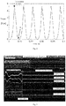
- the preset phase range for stopping the compressor may also be considered as the preset phase range in which the load of the compressor is relatively small. For example, as illustrated in Fig. 2 , it is assumed that the load of the compressor at a point A is minimal, the rotor phase at the point A may be acquired as the rotor phase P corresponding to the minimum load of the compressor.
- the rotor phase P corresponding to the minimum load of the compressor floats upward by the threshold L1 and the rotor phase P corresponding to the minimum load of the compressor floats downward by the threshold L2, to determine the preset phase range for stopping the compressor as [P-L2, P+Ll].
- the preset phase range for stopping the compressor may be [170°, 190°], further preferably may be [175°, 185°].
- the rotor phase corresponding to the minimum load of the compressor corresponds to an orientation of the rotor when suction and exhaust are finished, that is, an orientation of the rotor when the compressor finishes exhausting within a mechanical cycle.
- the refrigerant with a low temperature and a low pressure enters into a suction pipe of the compressor. And then the refrigerant is gradually compressed into the refrigerant with a high temperature and a high pressure.
- the refrigerant with the high temperature and the high pressure is rapidly emitted to an evaporator through an exhaust port of the compressor.
- a load pressure of the compressor is minimal after the refrigerant is released. Therefore, the rotor phase corresponding to the minimum load of the compressor is a phase of the rotor of the compressor after the refrigerant is emitted (i.e. when the compressor finishes exhausting).
- the rotor phase corresponding to the minimum load may be acquired according to a difference between the rotor phase corresponding to the minimum load and a mechanical zero-phase of the rotor, and according to an identification of the mechanical zero-phase.
- the rotor phase corresponding to the minimum load may be acquired according to a minimum amplitude of a torque current of the compressor or by acquiring a minimum amplitude of a compensation torque of the compressor.
- the compressor is controlled with a torque compensation using a torque compensation technique to reduce a vibration of a piping during the compressor is running.
- the amplitude of a compensation torque varies periodically with a refrigerant pressure and a load.
- the refrigerant pressure and the load are minimal, the corresponding amplitude of the compensation torque is minimal.
- the orientation of the rotor of the compressor corresponds to the rotor phase corresponding to the minimum load.
- the rotor phase corresponding to the minimum load of the compressor may be obtained directly by calibrating designed orientations of the rotor of the compressor.
- the rotor phase corresponding to the minimum load of the compressor may be obtained indirectly according to variables, such as, the amplitude of the torque current of the compressor or the amplitude of the compensation torque of the compressor.
- the rotor phase corresponding to the minimum load of the compressor may be obtained by identifying the mechanical zero-phase of the rotor of the compressor.
- the rotor phase corresponding to the minimum load of the compressor may be obtained by acquiring the minimum amplitude of the torque current or the minimum amplitude of the compensation torque.
- a current orientation of a rotor of the compressor is acquired and it is determined whether the phase of the rotor is within the preset phase range according to the current orientation of the rotor.
- the current orientation of the rotor of the compressor may be acquired by two methods.
- One of the two methods is by a direct measurement via sensors; another of the two methods is according to a calculation of a current of the compressor by measuring the current of the compressor.
- the compressor is controlled to stop to reduce a vibration and stress of a piping if determining that the phase of the rotor is within the preset phase range.
- the compressor is controlled to continue to run if it is determined that the phase of the rotor is not within the preset phase range for stopping the compressor.
- the compressor is stopped only if the phase of the rotor is within the preset phase range for stopping the compressor.
- the refrigerant pressure and the load vary periodically.
- the preset phase range for stopping the compressor is determined by floating the rotor phase corresponding to the minimum load of the compressor upwardly and downwardly.
- the compressor is stopped when the phase of the rotor of the compressor is within the preset phase range for stopping the compressor. As a result, the vibration and stress of the piping is smaller than that generated by directly stopping the compressor.
- the controlling module begins to control the compressor to stop.
- the current orientation of the rotor of the compressor is acquired in real time. If the phase of the rotor of the compressor is within the preset phase range for stopping the compressor, the compressor is controlled to stop immediately.
- the compressor is controlled to continue to run, until the phase of the rotor of the compressor is within the preset phase range for stopping the compressor, and the compressor is controlled to stop when the phase of the rotor of the compressor is within the preset phase range for stopping the compressor.
- the current orientation of the rotor of the compressor is acquired, and the compressor is controlled to stop if the phase of the rotor is within the preset phase range for stopping the compressor.
- a generated vibration and stress of a piping is smaller than that generated by directly stopping the compressor, to effectively reduce the vibration and stress of the piping at the moment that the compressor is stopped and to avoid a danger of breaking the piping.
- Fig. 3 is a flow chart illustrating a method for controlling a compressor in an air conditioner to stop according to a still another embodiment of the present disclosure. As illustrated in Fig. 3 , the method includes followings.
- the compressor is controlled to stop while the phase of the rotor of the compressor is within the phase range of [170°, 190°] according to the stop instruction.
- the compressor is controlled to stop while the phase of the rotor of the compressor is within the phase range of [170°, 190°] according to the stop instruction.
- a generated vibration and stress of a piping is smaller than that generated by directly stopping the compressor, to effectively reduce the vibration and stress of the piping at the moment that the compressor is stopped and to avoid a danger of breaking the piping.
- a load characteristic curve of the compressor when the compressor is running at the frequency of 60Hz is illustrated in Fig. 4 .
- the controlling module When the controlling module outputs the stop signal for stopping the compressor, if the phase of the rotor of the compressor is within the preset phase range for stopping the compressor, the compressor is stopped immediately. Otherwise, the compressor continues to run until the rotor of the compressor is within the preset phase range for stopping the compressor, and then the compressor is stopped when the rotor of the compressor is within the preset phase range for stopping the compressor.
- the rotor phase of the compressor corresponding to the minimum load of the compressor is 180°
- the preset phase range for stopping the compressor is 175-185°.
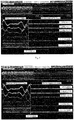
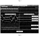
- Figs. 5-9 are waveform plots of phase currents vs. U phase drive signals of a compressor during a 100ms shutdown process in the related art.
- CH1, CH2 and MATH are a U phase current, a V phase current and a W phase current (10A/div) of the compressor respectively
- CH3 and CH4 are a drive signal at an upper bridge leg of the U phase (U+) and a drive signal at a lower bridge leg of the U phase (U-) respectively.
- the moment that the drive signal at the U phase is stopped is the moment that the compressor is stopped.
- stop phases of three phase current are not stable.
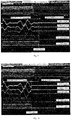
- Figs. 10-13 are waveform plots of phase currents vs. U phase drive signals of the compressor during a 100ms shutdown process according to a specific example of the present disclosure.
- CH1, CH2 and MATH are the U phase current
- CH3 and CH4 are the drive signal at the upper bridge leg of the U phase (U+) and the drive signal at the lower bridge leg of the U phase (U-) respectively.
- the moment that the drive signal at the U phase is stopped is the moment that the compressor is stopped.
- the stop phases of three phase current are essentially stable.
- Fig. 14 is a block diagram of a device for controlling a compressor in an air conditioner to stop according to an embodiment of the present disclosure. As illustrated in Fig. 14 , the device includes: an acquiring module 10, a rotor orientation acquiring module 20 and a controlling module 30.
- the acquiring module 10 is configured to acquire a rotor phase corresponding to a minimum load of the compressor.
- the rotor orientation acquiring module 20 is configured to acquire a current orientation of the rotor of the compressor during a shutdown process of the air conditioner.
- the controlling module 30 is configured to determine whether a phase of the rotor is the rotor phase corresponding to the minimum load according to the current orientation of the rotor, and to control the compressor to stop if determining that the phase of rotor is the rotor phase corresponding to the minimum load.
- controlling module 30 is configured to control the compressor to continue to run if it is determined that the phase of the rotor of the compressor is not the rotor phase corresponding to the minimum load of the compressor.
- the controlling module 30 controls the compressor to stop only if the phase of the rotor is the rotor phase corresponding to the minimum load of the compressor. It is to be illustrated that, within a refrigerant compression cycle of the compressor (particularly a compressor with a single rotor), the refrigerant pressure and the load vary periodically, when the phase of the rotor is near the rotor phase corresponding to the minimum load of the compressor, the refrigerant pressure is relatively small accordingly. Therefore, the compressor is stopped when the phase of the rotor of the compressor is the rotor phase corresponding to the minimum phase of the compressor. As a result, the vibration and stress of the piping is smaller than that generated by directly stopping the compressor.
- the controlling module 30 begins to control the compressor to stop.
- the rotor orientation acquiring module 20 may acquire the current orientation of the rotor of the compressor. If the phase of the rotor of the compressor is the rotor phase corresponding to the minimum load, the controlling module 30 controls the compressor to stop immediately.
- the controlling module 30 controls the compressor to continue to run until the phase of the rotor of the compressor is the rotor phase corresponding to the minimum load of the compressor, and the controlling module 30 controls the compressor to stop when the phase of the rotor of the compressor is the rotor phase corresponding to the minimum load of the compressor.
- the rotor phase corresponding to the minimum load corresponds to an orientation of the rotor when a suction and an exhaust are finished, that is, an orientation of the rotor when the compressor finishes exhausting within a mechanical cycle.
- the refrigerant with a low temperature and a low pressure enters into a suction pipe of the compressor. And then the refrigerant with the low temperature and the low pressure is gradually compressed into the refrigerant with a high temperature and a high pressure.
- the refrigerant with the high temperature and the high pressure is rapidly emitted to an evaporator through an exhaust port of the compressor.
- a load pressure of the compressor is minimal after the refrigerant is released. Therefore, the rotor phase corresponding to the minimum load of the compressor is a phase of the rotor of the compressor after the refrigerant is emitted (i.e. when the compressor finishes exhausting). With the phase of the rotor of the compressor when the exhausting is finished, the compressor is controlled to stop such that the vibration and stress of the piping is relatively small at the moment when the compressor is stopped.
- the acquiring module 10 may acquire the rotor phase corresponding to the minimum load of the compressor according to a difference between the rotor phase corresponding to the minimum load and a mechanical zero-phase of the rotor, and according to an identification of the mechanical zero-phase.
- the acquiring module 10 may acquire the rotor phase corresponding to the minimum load of the compressor according to a minimum amplitude of a torque current of the compressor or by acquiring a minimum amplitude of a compensation torque of the compressor.
- the compressor is controlled with a torque compensation using a torque compensation technique to reduce a vibration of a piping during the compressor is running.
- the amplitude of a compensation torque varies periodically with a refrigerant pressure and a load.
- the refrigerant pressure and the load are minimal, the corresponding amplitude of the compensation torque is minimal.
- the orientation of the rotor of the compressor corresponds to the rotor phase corresponding to the minimum load.
- the rotor phase corresponding to the minimum load of the compressor may be obtained directly by calibrating designed orientations of the rotor of the compressor.
- the rotor phase corresponding to the minimum load of the compressor may be obtained indirectly according to variables, such as, the amplitude of the torque current of the compressor or the amplitude of the compensation torque of the compressor.
- the acquiring module 10 may acquire the rotor phase corresponding to the minimum load of the compressor by identifying the mechanical zero-phase of the rotor of the compressor.
- the acquiring module 10 may acquire the rotor phase corresponding to the minimum load of the compressor by acquiring the minimum amplitude of the torque current or the minimum amplitude of the compensation torque.
- the rotor orientation acquiring module 20 may acquire the current orientation of the rotor of the compressor by two methods.
- One of the two methods is by a direct measurement via sensors; another of the two methods is according to a calculation of a current of the compressor by measuring the current of the compressor.
- the controlling module controls the compressor to stop if the phase of the rotor is within the preset phase range.
- Embodiments of the present disclosure further provide an air conditioner.
- the air conditioner includes the above device for controlling a compressor in an air conditioner to stop.
- the vibration and stress of the piping may be reduced at the moment that the compressor is stopped and to avoid a danger of breaking the piping.
- Fig. 15 is a block diagram of a device for controlling a compressor in an air conditioner to stop according to another embodiment of the present disclosure. As illustrated in Fig. 15 , the device includes: an acquiring module 11, a rotor orientation acquiring module 21 and a controlling module 31.
- the acquiring module 11 is configured to acquire a preset phase range for stopping the compressor.
- the rotor orientation acquiring module 21 is configured to acquire a current orientation of a rotor of the compressor during a shutdown process of the air conditioner.
- the controlling module 31 is configured to determine whether a phase of the rotor is within the preset phase range according to the current orientation of the rotor, and to control the compressor to stop to reduce a vibration and stress of a piping if determining that the phase of the rotor is within the preset phase range.
- controlling module 31 is configured to control the compressor to continue to run if the phase of the rotor of the compressor is not within the preset phase range for stopping the compressor.
- the controlling module 31 controls the compressor to stop only if the phase of the rotor is within the preset phase range for stopping the compressor. It is to be illustrated that, within a refrigerant compression cycle of the compressor (particularly a compressor with a single rotor), the refrigerant pressure and the load vary periodically. When the phase of the rotor is near the rotor phase corresponding to the minimum load of the compressor, the refrigerant pressure is relatively small accordingly. Therefore, the preset phase range for stopping the compressor is determined by floating the rotor phase corresponding to the minimum load of the compressor upwardly and downwardly. And the compressor is stopped when the phase of the rotor of the compressor is within the preset phase range for stopping the compressor. As a result, the vibration and stress of the piping is smaller than that generated by directly stopping the compressor.
- the controlling module 31 begins to control the compressor to stop.
- the rotor orientation acquiring module 21 may acquire the current orientation of the rotor of the compressor. If the phase of the rotor of the compressor is within the preset phase range for stopping the compressor, the controlling module 31 controls the compressor to stop immediately.
- the controlling module 31 controls the compressor to continue to run, until the phase of the rotor of the compressor is within the preset phase range for stopping the compressor, and the compressor is controlled to stop when the phase of the rotor of the compressor is within the preset phase range for stopping the compressor.
- the present phase range is obtained according to an experimental test and is stored to the air condition to be invoked.
- the experimental test is performed on the compressor of the air conditioner to determine the rotor phase corresponding to the minimum load of the compressor. And then, the rotor phase corresponding to the minimum load of the compressor floats upward by a first preset threshold and downward by a second preset threshold as the preset phase range for stopping the compressor.
- the preset phase range for stopping the compressor may also be considered as the preset phase range in which the load of the compressor is relatively small. For example, as illustrated in Fig. 2 , it is assumed that the load of the compressor at a point A is minimal, the rotor phase at the point A may be acquired as the rotor phase P corresponding to the minimum load of the compressor.
- the rotor phase P corresponding to the minimum load of the compressor floats upward by the threshold L1 and the rotor phase P corresponding to the minimum load of the compressor floats downward by the threshold L2, to determine the preset phase range for stopping the compressor as [P-L2, P+L1].
- the preset phase range for stopping the compressor may be [170°, 190°], further preferably may be [175°, 185°].
- the rotor phase corresponding to the minimum load of the compressor corresponds to an orientation of the rotor when suction and exhaust are finished, that is, an orientation of the rotor when the compressor finishes exhausting within a mechanical cycle.
- the refrigerant with a low temperature and a low pressure enters into a suction pipe of the compressor. And then the refrigerant is gradually compressed into the refrigerant with a high temperature and a high pressure.
- the refrigerant with a high temperature and a high pressure is rapidly emitted to an evaporator through an exhaust port of the compressor.
- a load pressure of the compressor is minimal after the refrigerant is released. Therefore, the rotor phase corresponding to the minimum load of the compressor is a phase of the rotor of the compressor after the refrigerant is emitted (i.e. when the compressor finishes exhausting).
- the rotor phase corresponding to the minimum load may be acquired according to a difference between the rotor phase corresponding to the minimum load and a mechanical zero-phase of the rotor, and according to an identification of the mechanical zero-phase.
- the rotor phase corresponding to the minimum load may be acquired according to a minimum amplitude of a torque current of the compressor or by acquiring a minimum amplitude of a compensation torque of the compressor.
- the compressor is controlled with a torque compensation using a torque compensation technique to reduce a vibration of a piping during the compressor is running.
- the amplitude of a compensation torque varies periodically with a refrigerant pressure and a load.
- the refrigerant pressure and the load are minimal, the corresponding amplitude of the compensation torque is minimal.
- the orientation of the rotor of the compressor corresponds to the rotor phase corresponding to the minimum load.
- the rotor phase corresponding to the minimum load of the compressor may be obtained directly by calibrating designed orientations of the rotor of the compressor.
- the rotor phase corresponding to the minimum load of the compressor may be obtained indirectly according to variables, such as, the amplitude of the torque current of the compressor or the amplitude of the compensation torque of the compressor.
- the rotor phase corresponding to the minimum load of the compressor may be obtained by identifying the mechanical zero-phase of the rotor of the compressor.
- the rotor phase corresponding to the minimum load of the compressor may be obtained by acquiring the minimum amplitude of the torque current or the minimum amplitude of the compensation torque.
- the controlling module controls the compressor to stop if the phase of the rotor is within the preset phase range.
- Embodiments of the present disclosure further provide an air conditioner.
- the air conditioner includes the above device for controlling a compressor in an air conditioner to stop.
- the vibration and stress of the piping may be reduced at the moment that the compressor is stopped and to avoid a danger of breaking the piping.
- Fig. 16 is a block diagram of a device for controlling a compressor in an air conditioner to stop according to a still another embodiment of the present disclosure. As illustrated in Fig. 16 , the device includes a receiving module 12 and a controlling module 32.
- the receiving module 12 is configured to receive a stop instruction.
- the controlling module 32 is configured to control the compressor to stop while the phase of the rotor of the compressor is within the phase range of [170°, 190°] according to the stop instruction.
- the compressor is controlled to stop while the phase of the rotor of the compressor is within the phase range of [170°, 190°] according to the stop instruction.
- a generated vibration and stress of a piping is smaller than that generated by directly stopping the compressor, to effectively reduce the vibration and stress of the piping at the moment that the compressor is stopped and to avoid a danger of breaking the piping.
- Embodiments of the present disclosure further provide an air conditioner.
- the air conditioner includes the above device for controlling a compressor in an air conditioner to stop.
- the vibration and stress of the piping may be reduced at the moment that the compressor is stopped and to avoid a danger of breaking the piping.
- first and second are used herein for purposes of description and are not intended to indicate or imply relative importance or significance.
- feature defined with “first” and “second” may comprise one or more this feature distinctly or implicitly.
- a plurality of' means two or more than two, unless specified otherwise.
- the terms “mounted,” “connected,” “coupled” and “fixed” are understood broadly, such as fixed, detachable mountings, connections and couplings or integrated, and can be mechanical or electrical mountings, connections and couplings, and also can be direct and via media indirect mountings, connections, and couplings, and further can be inner mountings, connections and couplings of two components or interaction relations between two components, which can be understood by those skilled in the art according to the detail embodiment of the present disclosure.
- the first characteristic is “on” or “under” the second characteristic refers to the first characteristic and the second characteristic can be direct or via media indirect mountings, connections, and couplings.
- the first characteristic is “on”, “above”, “over” the second characteristic may refer to the first characteristic is right over the second characteristic or is diagonal above the second characteristic, or just refer to the horizontal height of the first characteristic is higher than the horizontal height of the second characteristic.
- the first characteristic is “below” or “under” the second characteristic may refer to the first characteristic is right over the second characteristic or is diagonal under the second characteristic, or just refer to the horizontal height of the first characteristic is lower than the horizontal height of the second characteristic.
Landscapes
- Engineering & Computer Science (AREA)
- Mechanical Engineering (AREA)
- General Engineering & Computer Science (AREA)
- Combustion & Propulsion (AREA)
- Chemical & Material Sciences (AREA)
- Power Engineering (AREA)
- Computer Hardware Design (AREA)
- Control Of Ac Motors In General (AREA)
- Air Conditioning Control Device (AREA)
- Control Of Motors That Do Not Use Commutators (AREA)
- Control Of Positive-Displacement Pumps (AREA)
- Air-Conditioning For Vehicles (AREA)
- Compressor (AREA)
Priority Applications (2)
| Application Number | Priority Date | Filing Date | Title |
|---|---|---|---|
| HRP20210666TT HRP20210666T1 (hr) | 2016-03-09 | 2016-04-01 | Klima uređaj, upravljanje postupkom isključivanja i uređaj za njegov kompresor |
| PL16888598T PL3258182T3 (pl) | 2016-03-09 | 2016-04-01 | Klimatyzator i sposób sterowania wyłączaniem oraz urządzenie dla sprężarki klimatyzatora |
Applications Claiming Priority (2)
| Application Number | Priority Date | Filing Date | Title |
|---|---|---|---|
| CN201610134311.6A CN105715524A (zh) | 2016-03-09 | 2016-03-09 | 空调器及其压缩机的停机控制方法和装置 |
| PCT/CN2016/078284 WO2017152444A1 (fr) | 2016-03-09 | 2016-04-01 | Climatiseur, procédé de commande d'arrêt et dispositif pour compresseur associé |
Publications (3)
| Publication Number | Publication Date |
|---|---|
| EP3258182A1 true EP3258182A1 (fr) | 2017-12-20 |
| EP3258182A4 EP3258182A4 (fr) | 2018-02-21 |
| EP3258182B1 EP3258182B1 (fr) | 2021-01-27 |
Family
ID=56157517
Family Applications (1)
| Application Number | Title | Priority Date | Filing Date |
|---|---|---|---|
| EP16888598.6A Active EP3258182B1 (fr) | 2016-03-09 | 2016-04-01 | Climatiseur, procédé de commande d'arrêt et dispositif pour compresseur associé |
Country Status (8)
| Country | Link |
|---|---|
| US (1) | US10677241B2 (fr) |
| EP (1) | EP3258182B1 (fr) |
| CN (1) | CN105715524A (fr) |
| BR (1) | BR112017017679B1 (fr) |
| ES (1) | ES2866047T3 (fr) |
| HR (1) | HRP20210666T1 (fr) |
| PL (1) | PL3258182T3 (fr) |
| WO (1) | WO2017152444A1 (fr) |
Families Citing this family (10)
| Publication number | Priority date | Publication date | Assignee | Title |
|---|---|---|---|---|
| DE102016222958A1 (de) * | 2016-11-22 | 2018-05-24 | BSH Hausgeräte GmbH | Verfahren zum Anhalten eines Hubkolben-Verdichters und Hubkolben-Verdichter eines Kältegerätes, Klimagerätes oder einer Wärmepumpe sowie Kältegerät, Klimageräts oder Wärmepumpe damit |
| CN106930932B (zh) * | 2017-04-12 | 2019-03-08 | 珠海格力电器股份有限公司 | 压缩机停机控制装置、系统及方法 |
| CN107101345B (zh) * | 2017-06-02 | 2020-09-11 | 广东美的制冷设备有限公司 | 空调器及其压缩机停机控制方法和计算机可读存储介质 |
| CN108730187A (zh) * | 2018-05-04 | 2018-11-02 | 海信科龙电器股份有限公司 | 一种包含压缩机的家用电器及其停机控制方法 |
| JP7308949B2 (ja) * | 2019-07-04 | 2023-07-14 | 三菱電機株式会社 | 電動機駆動装置及び冷凍サイクル適用機器 |
| CN111947360B (zh) * | 2020-08-15 | 2022-04-05 | 广东芬尼克兹节能设备有限公司 | 一种降低铜管振幅应力控制方法、装置、设备及存储介质 |
| CN112460771A (zh) * | 2020-11-30 | 2021-03-09 | 珠海格力电器股份有限公司 | 一种压缩机控制方法、装置、系统及存储介质 |
| CN114659226A (zh) * | 2022-03-03 | 2022-06-24 | 海信(山东)空调有限公司 | 空调器以及压缩机停机控制方法 |
| CN115200186A (zh) * | 2022-06-24 | 2022-10-18 | 宁波奥克斯电气股份有限公司 | 空调管路应力的控制方法、装置及空调器 |
| CN116335942B (zh) * | 2022-11-25 | 2025-12-23 | 海信(广东)空调有限公司 | 变频控制器的停机控制方法及变频空调 |
Family Cites Families (11)
| Publication number | Priority date | Publication date | Assignee | Title |
|---|---|---|---|---|
| JPS6115589A (ja) * | 1984-06-28 | 1986-01-23 | Daikin Ind Ltd | 回転圧縮機の振動低減装置 |
| EP0353520B1 (fr) * | 1988-07-26 | 1994-09-14 | Kabushiki Kaisha Toshiba | Méthode et appareil pour détecter la position d'arbre d'un compresseur pour un appareil de conditionnement d'air et appareil de commande pour arrêter le compresseur par mise en service d'appareil de détection de la position d'arbre |
| JP2001037281A (ja) * | 1999-05-18 | 2001-02-09 | Matsushita Electric Ind Co Ltd | 電動機のトルク制御装置 |
| JP3544338B2 (ja) * | 2000-03-23 | 2004-07-21 | シャープ株式会社 | 圧縮機モータの制御装置 |
| JP4265601B2 (ja) * | 2003-03-17 | 2009-05-20 | パナソニック株式会社 | 空気調和機 |
| KR20050042953A (ko) * | 2003-11-04 | 2005-05-11 | 엘지전자 주식회사 | 인버터 압축기 및 정속 압축기를 구비한 공조시스템의운전제어방법 |
| JP5433400B2 (ja) * | 2009-12-24 | 2014-03-05 | カルソニックカンセイ株式会社 | ベーン型圧縮機 |
| US8657585B2 (en) * | 2010-02-08 | 2014-02-25 | Lg Electronics Inc. | Apparatus for driving compressor of air conditioner and method for driving the same |
| DE102012006492B4 (de) * | 2011-04-01 | 2025-02-27 | Secop Gmbh | Sensorlose Rotorpositionsbestimmung |
| KR102037290B1 (ko) * | 2013-01-29 | 2019-10-28 | 엘지전자 주식회사 | 압축기 진동 저감 장치 및 그 제어방법 |
| CN105258301A (zh) * | 2015-11-17 | 2016-01-20 | 广东美的制冷设备有限公司 | 空调器及空调器中压缩机的控制方法和装置 |
-
2016
- 2016-03-09 CN CN201610134311.6A patent/CN105715524A/zh active Pending
- 2016-04-01 HR HRP20210666TT patent/HRP20210666T1/hr unknown
- 2016-04-01 PL PL16888598T patent/PL3258182T3/pl unknown
- 2016-04-01 ES ES16888598T patent/ES2866047T3/es active Active
- 2016-04-01 EP EP16888598.6A patent/EP3258182B1/fr active Active
- 2016-04-01 WO PCT/CN2016/078284 patent/WO2017152444A1/fr not_active Ceased
- 2016-04-01 BR BR112017017679-3A patent/BR112017017679B1/pt active IP Right Grant
-
2018
- 2018-03-02 US US15/910,923 patent/US10677241B2/en active Active
Also Published As
| Publication number | Publication date |
|---|---|
| US10677241B2 (en) | 2020-06-09 |
| HRP20210666T1 (hr) | 2021-05-28 |
| BR112017017679B1 (pt) | 2023-03-07 |
| EP3258182A4 (fr) | 2018-02-21 |
| PL3258182T3 (pl) | 2021-08-02 |
| CN105715524A (zh) | 2016-06-29 |
| US20180195508A1 (en) | 2018-07-12 |
| EP3258182B1 (fr) | 2021-01-27 |
| BR112017017679A2 (pt) | 2018-04-10 |
| WO2017152444A1 (fr) | 2017-09-14 |
| ES2866047T3 (es) | 2021-10-19 |
Similar Documents
| Publication | Publication Date | Title |
|---|---|---|
| EP3258182B1 (fr) | Climatiseur, procédé de commande d'arrêt et dispositif pour compresseur associé | |
| CN105698453A (zh) | 变频空调器及其压缩机的停机控制方法和装置 | |
| DK180025B1 (en) | Controls and operation of variable frequency drives (frequency converters) | |
| CN107294472B (zh) | 一种电机控制方法、装置及设备 | |
| US9825575B2 (en) | Power converting apparatus, dehumidifier, air conditioner, and refrigeration apparatus | |
| CN106655940A (zh) | 空调器及压缩机的谐波转矩补偿方法、控制方法和装置 | |
| CN104913589B (zh) | 一种冰箱间室温度动态补偿的精确控温方法及冰箱 | |
| CN107356444B (zh) | 用于变频空调器的测试方法及测试系统 | |
| US10317894B2 (en) | No flow detection means for sensorless pumping control applications | |
| KR101601405B1 (ko) | 모터 구동시스템의 고장 검출 방법 | |
| CN107317502B (zh) | 逆变器死区补偿方法、装置和逆变器 | |
| EP2578956A1 (fr) | Procédé permettant de commander un ventilateur pour échangeur de chaleur de source de chaleur et dispositif de climatisation | |
| CN104563219A (zh) | 一种无外部传感器的供水控制方法 | |
| RU2012129165A (ru) | Устройство управления синхронной машиной с постоянными магнитами | |
| CN107387382A (zh) | 压缩机振幅的控制方法、压缩机系统及制冷设备 | |
| CN105258301A (zh) | 空调器及空调器中压缩机的控制方法和装置 | |
| CN110906541A (zh) | 供暖用变频热泵热水器制冷剂泄漏精确判断方法 | |
| US20140260343A1 (en) | Variable frequency drive apparatuses, systems, and methods and controls for same | |
| CN105699896B (zh) | 一种适用于感应电机转子故障诊断方法 | |
| CN105627499A (zh) | 空调进入除霜模式的控制装置、方法及空调器 | |
| KR101897934B1 (ko) | 모터 구동 방법과 장치, 전기 제품 | |
| MX2025005534A (es) | Monitoreo del desempe?o de una valvula de expansion en un sistema de refrigeracion | |
| KR101765590B1 (ko) | 엔진 제어 장치 및 방법 | |
| US20190301478A1 (en) | Compressor anti-surge protectoin under wet gas conditions | |
| JP2011174481A (ja) | 配管振動低減装置 |
Legal Events
| Date | Code | Title | Description |
|---|---|---|---|
| STAA | Information on the status of an ep patent application or granted ep patent |
Free format text: STATUS: UNKNOWN |
|
| STAA | Information on the status of an ep patent application or granted ep patent |
Free format text: STATUS: THE INTERNATIONAL PUBLICATION HAS BEEN MADE |
|
| PUAI | Public reference made under article 153(3) epc to a published international application that has entered the european phase |
Free format text: ORIGINAL CODE: 0009012 |
|
| STAA | Information on the status of an ep patent application or granted ep patent |
Free format text: STATUS: REQUEST FOR EXAMINATION WAS MADE |
|
| 17P | Request for examination filed |
Effective date: 20170811 |
|
| AK | Designated contracting states |
Kind code of ref document: A1 Designated state(s): AL AT BE BG CH CY CZ DE DK EE ES FI FR GB GR HR HU IE IS IT LI LT LU LV MC MK MT NL NO PL PT RO RS SE SI SK SM TR |
|
| AX | Request for extension of the european patent |
Extension state: BA ME |
|
| A4 | Supplementary search report drawn up and despatched |
Effective date: 20180119 |
|
| RIC1 | Information provided on ipc code assigned before grant |
Ipc: F04B 49/06 20060101ALI20180115BHEP Ipc: F04B 49/02 20060101ALI20180115BHEP Ipc: F24F 11/00 20180101AFI20180115BHEP |
|
| DAV | Request for validation of the european patent (deleted) | ||
| DAX | Request for extension of the european patent (deleted) | ||
| STAA | Information on the status of an ep patent application or granted ep patent |
Free format text: STATUS: EXAMINATION IS IN PROGRESS |
|
| 17Q | First examination report despatched |
Effective date: 20200421 |
|
| GRAP | Despatch of communication of intention to grant a patent |
Free format text: ORIGINAL CODE: EPIDOSNIGR1 |
|
| STAA | Information on the status of an ep patent application or granted ep patent |
Free format text: STATUS: GRANT OF PATENT IS INTENDED |
|
| INTG | Intention to grant announced |
Effective date: 20201112 |
|
| GRAS | Grant fee paid |
Free format text: ORIGINAL CODE: EPIDOSNIGR3 |
|
| GRAA | (expected) grant |
Free format text: ORIGINAL CODE: 0009210 |
|
| STAA | Information on the status of an ep patent application or granted ep patent |
Free format text: STATUS: THE PATENT HAS BEEN GRANTED |
|
| AK | Designated contracting states |
Kind code of ref document: B1 Designated state(s): AL AT BE BG CH CY CZ DE DK EE ES FI FR GB GR HR HU IE IS IT LI LT LU LV MC MK MT NL NO PL PT RO RS SE SI SK SM TR |
|
| REG | Reference to a national code |
Ref country code: GB Ref legal event code: FG4D |
|
| REG | Reference to a national code |
Ref country code: CH Ref legal event code: EP |
|
| REG | Reference to a national code |
Ref country code: AT Ref legal event code: REF Ref document number: 1358700 Country of ref document: AT Kind code of ref document: T Effective date: 20210215 |
|
| REG | Reference to a national code |
Ref country code: IE Ref legal event code: FG4D |
|
| REG | Reference to a national code |
Ref country code: DE Ref legal event code: R096 Ref document number: 602016052259 Country of ref document: DE |
|
| REG | Reference to a national code |
Ref country code: HR Ref legal event code: TUEP Ref document number: P20210666 Country of ref document: HR |
|
| REG | Reference to a national code |
Ref country code: HR Ref legal event code: ODRP Ref document number: P20210666 Country of ref document: HR Payment date: 20210427 Year of fee payment: 6 |
|
| REG | Reference to a national code |
Ref country code: GR Ref legal event code: EP Ref document number: 20210401070 Country of ref document: GR Effective date: 20210519 |
|
| REG | Reference to a national code |
Ref country code: HR Ref legal event code: T1PR Ref document number: P20210666 Country of ref document: HR |
|
| REG | Reference to a national code |
Ref country code: NL Ref legal event code: MP Effective date: 20210127 |
|
| REG | Reference to a national code |
Ref country code: LT Ref legal event code: MG9D |
|
| REG | Reference to a national code |
Ref country code: AT Ref legal event code: MK05 Ref document number: 1358700 Country of ref document: AT Kind code of ref document: T Effective date: 20210127 |
|
| PG25 | Lapsed in a contracting state [announced via postgrant information from national office to epo] |
Ref country code: PT Free format text: LAPSE BECAUSE OF FAILURE TO SUBMIT A TRANSLATION OF THE DESCRIPTION OR TO PAY THE FEE WITHIN THE PRESCRIBED TIME-LIMIT Effective date: 20210527 Ref country code: NO Free format text: LAPSE BECAUSE OF FAILURE TO SUBMIT A TRANSLATION OF THE DESCRIPTION OR TO PAY THE FEE WITHIN THE PRESCRIBED TIME-LIMIT Effective date: 20210427 Ref country code: FI Free format text: LAPSE BECAUSE OF FAILURE TO SUBMIT A TRANSLATION OF THE DESCRIPTION OR TO PAY THE FEE WITHIN THE PRESCRIBED TIME-LIMIT Effective date: 20210127 Ref country code: BG Free format text: LAPSE BECAUSE OF FAILURE TO SUBMIT A TRANSLATION OF THE DESCRIPTION OR TO PAY THE FEE WITHIN THE PRESCRIBED TIME-LIMIT Effective date: 20210427 Ref country code: LT Free format text: LAPSE BECAUSE OF FAILURE TO SUBMIT A TRANSLATION OF THE DESCRIPTION OR TO PAY THE FEE WITHIN THE PRESCRIBED TIME-LIMIT Effective date: 20210127 |
|
| PG25 | Lapsed in a contracting state [announced via postgrant information from national office to epo] |
Ref country code: SE Free format text: LAPSE BECAUSE OF FAILURE TO SUBMIT A TRANSLATION OF THE DESCRIPTION OR TO PAY THE FEE WITHIN THE PRESCRIBED TIME-LIMIT Effective date: 20210127 Ref country code: AT Free format text: LAPSE BECAUSE OF FAILURE TO SUBMIT A TRANSLATION OF THE DESCRIPTION OR TO PAY THE FEE WITHIN THE PRESCRIBED TIME-LIMIT Effective date: 20210127 Ref country code: RS Free format text: LAPSE BECAUSE OF FAILURE TO SUBMIT A TRANSLATION OF THE DESCRIPTION OR TO PAY THE FEE WITHIN THE PRESCRIBED TIME-LIMIT Effective date: 20210127 Ref country code: LV Free format text: LAPSE BECAUSE OF FAILURE TO SUBMIT A TRANSLATION OF THE DESCRIPTION OR TO PAY THE FEE WITHIN THE PRESCRIBED TIME-LIMIT Effective date: 20210127 |
|
| PG25 | Lapsed in a contracting state [announced via postgrant information from national office to epo] |
Ref country code: IS Free format text: LAPSE BECAUSE OF FAILURE TO SUBMIT A TRANSLATION OF THE DESCRIPTION OR TO PAY THE FEE WITHIN THE PRESCRIBED TIME-LIMIT Effective date: 20210527 |
|
| REG | Reference to a national code |
Ref country code: ES Ref legal event code: FG2A Ref document number: 2866047 Country of ref document: ES Kind code of ref document: T3 Effective date: 20211019 |
|
| REG | Reference to a national code |
Ref country code: DE Ref legal event code: R097 Ref document number: 602016052259 Country of ref document: DE |
|
| PG25 | Lapsed in a contracting state [announced via postgrant information from national office to epo] |
Ref country code: SM Free format text: LAPSE BECAUSE OF FAILURE TO SUBMIT A TRANSLATION OF THE DESCRIPTION OR TO PAY THE FEE WITHIN THE PRESCRIBED TIME-LIMIT Effective date: 20210127 Ref country code: CZ Free format text: LAPSE BECAUSE OF FAILURE TO SUBMIT A TRANSLATION OF THE DESCRIPTION OR TO PAY THE FEE WITHIN THE PRESCRIBED TIME-LIMIT Effective date: 20210127 Ref country code: EE Free format text: LAPSE BECAUSE OF FAILURE TO SUBMIT A TRANSLATION OF THE DESCRIPTION OR TO PAY THE FEE WITHIN THE PRESCRIBED TIME-LIMIT Effective date: 20210127 |
|
| PG25 | Lapsed in a contracting state [announced via postgrant information from national office to epo] |
Ref country code: DK Free format text: LAPSE BECAUSE OF FAILURE TO SUBMIT A TRANSLATION OF THE DESCRIPTION OR TO PAY THE FEE WITHIN THE PRESCRIBED TIME-LIMIT Effective date: 20210127 Ref country code: MC Free format text: LAPSE BECAUSE OF FAILURE TO SUBMIT A TRANSLATION OF THE DESCRIPTION OR TO PAY THE FEE WITHIN THE PRESCRIBED TIME-LIMIT Effective date: 20210127 Ref country code: SK Free format text: LAPSE BECAUSE OF FAILURE TO SUBMIT A TRANSLATION OF THE DESCRIPTION OR TO PAY THE FEE WITHIN THE PRESCRIBED TIME-LIMIT Effective date: 20210127 Ref country code: RO Free format text: LAPSE BECAUSE OF FAILURE TO SUBMIT A TRANSLATION OF THE DESCRIPTION OR TO PAY THE FEE WITHIN THE PRESCRIBED TIME-LIMIT Effective date: 20210127 |
|
| PLBE | No opposition filed within time limit |
Free format text: ORIGINAL CODE: 0009261 |
|
| STAA | Information on the status of an ep patent application or granted ep patent |
Free format text: STATUS: NO OPPOSITION FILED WITHIN TIME LIMIT |
|
| GBPC | Gb: european patent ceased through non-payment of renewal fee |
Effective date: 20210427 |
|
| PG25 | Lapsed in a contracting state [announced via postgrant information from national office to epo] |
Ref country code: LU Free format text: LAPSE BECAUSE OF NON-PAYMENT OF DUE FEES Effective date: 20210401 |
|
| 26N | No opposition filed |
Effective date: 20211028 |
|
| REG | Reference to a national code |
Ref country code: BE Ref legal event code: MM Effective date: 20210430 |
|
| PG25 | Lapsed in a contracting state [announced via postgrant information from national office to epo] |
Ref country code: GB Free format text: LAPSE BECAUSE OF NON-PAYMENT OF DUE FEES Effective date: 20210427 Ref country code: LI Free format text: LAPSE BECAUSE OF NON-PAYMENT OF DUE FEES Effective date: 20210430 Ref country code: CH Free format text: LAPSE BECAUSE OF NON-PAYMENT OF DUE FEES Effective date: 20210430 Ref country code: AL Free format text: LAPSE BECAUSE OF FAILURE TO SUBMIT A TRANSLATION OF THE DESCRIPTION OR TO PAY THE FEE WITHIN THE PRESCRIBED TIME-LIMIT Effective date: 20210127 |
|
| PG25 | Lapsed in a contracting state [announced via postgrant information from national office to epo] |
Ref country code: SI Free format text: LAPSE BECAUSE OF FAILURE TO SUBMIT A TRANSLATION OF THE DESCRIPTION OR TO PAY THE FEE WITHIN THE PRESCRIBED TIME-LIMIT Effective date: 20210127 |
|
| PG25 | Lapsed in a contracting state [announced via postgrant information from national office to epo] |
Ref country code: IE Free format text: LAPSE BECAUSE OF NON-PAYMENT OF DUE FEES Effective date: 20210401 |
|
| REG | Reference to a national code |
Ref country code: HR Ref legal event code: ODRP Ref document number: P20210666 Country of ref document: HR Payment date: 20220331 Year of fee payment: 7 |
|
| PG25 | Lapsed in a contracting state [announced via postgrant information from national office to epo] |
Ref country code: IS Free format text: LAPSE BECAUSE OF FAILURE TO SUBMIT A TRANSLATION OF THE DESCRIPTION OR TO PAY THE FEE WITHIN THE PRESCRIBED TIME-LIMIT Effective date: 20210527 |
|
| PG25 | Lapsed in a contracting state [announced via postgrant information from national office to epo] |
Ref country code: BE Free format text: LAPSE BECAUSE OF NON-PAYMENT OF DUE FEES Effective date: 20210430 |
|
| REG | Reference to a national code |
Ref country code: HR Ref legal event code: ODRP Ref document number: P20210666 Country of ref document: HR Payment date: 20230329 Year of fee payment: 8 |
|
| PG25 | Lapsed in a contracting state [announced via postgrant information from national office to epo] |
Ref country code: HU Free format text: LAPSE BECAUSE OF FAILURE TO SUBMIT A TRANSLATION OF THE DESCRIPTION OR TO PAY THE FEE WITHIN THE PRESCRIBED TIME-LIMIT; INVALID AB INITIO Effective date: 20160401 |
|
| PG25 | Lapsed in a contracting state [announced via postgrant information from national office to epo] |
Ref country code: NL Free format text: LAPSE BECAUSE OF NON-PAYMENT OF DUE FEES Effective date: 20210127 Ref country code: CY Free format text: LAPSE BECAUSE OF FAILURE TO SUBMIT A TRANSLATION OF THE DESCRIPTION OR TO PAY THE FEE WITHIN THE PRESCRIBED TIME-LIMIT Effective date: 20210127 |
|
| P01 | Opt-out of the competence of the unified patent court (upc) registered |
Effective date: 20230526 |
|
| REG | Reference to a national code |
Ref country code: HR Ref legal event code: ODRP Ref document number: P20210666 Country of ref document: HR Payment date: 20240326 Year of fee payment: 9 |
|
| PG25 | Lapsed in a contracting state [announced via postgrant information from national office to epo] |
Ref country code: MK Free format text: LAPSE BECAUSE OF FAILURE TO SUBMIT A TRANSLATION OF THE DESCRIPTION OR TO PAY THE FEE WITHIN THE PRESCRIBED TIME-LIMIT Effective date: 20210127 |
|
| PG25 | Lapsed in a contracting state [announced via postgrant information from national office to epo] |
Ref country code: MT Free format text: LAPSE BECAUSE OF FAILURE TO SUBMIT A TRANSLATION OF THE DESCRIPTION OR TO PAY THE FEE WITHIN THE PRESCRIBED TIME-LIMIT Effective date: 20210127 |
|
| REG | Reference to a national code |
Ref country code: HR Ref legal event code: ODRP Ref document number: P20210666 Country of ref document: HR Payment date: 20250313 Year of fee payment: 10 |
|
| PG25 | Lapsed in a contracting state [announced via postgrant information from national office to epo] |
Ref country code: TR Free format text: LAPSE BECAUSE OF FAILURE TO SUBMIT A TRANSLATION OF THE DESCRIPTION OR TO PAY THE FEE WITHIN THE PRESCRIBED TIME-LIMIT Effective date: 20210127 |
|
| REG | Reference to a national code |
Ref country code: HR Ref legal event code: ODRP Ref document number: P20210666 Country of ref document: HR Payment date: 20260324 Year of fee payment: 11 |
|
| PGFP | Annual fee paid to national office [announced via postgrant information from national office to epo] |
Ref country code: ES Payment date: 20260504 Year of fee payment: 11 |
|
| PGFP | Annual fee paid to national office [announced via postgrant information from national office to epo] |
Ref country code: PL Payment date: 20260401 Year of fee payment: 11 |
|
| PGFP | Annual fee paid to national office [announced via postgrant information from national office to epo] |
Ref country code: GR Payment date: 20260429 Year of fee payment: 11 Ref country code: IT Payment date: 20260423 Year of fee payment: 11 |
|
| PGFP | Annual fee paid to national office [announced via postgrant information from national office to epo] |
Ref country code: DE Payment date: 20260427 Year of fee payment: 11 |
|
| PGFP | Annual fee paid to national office [announced via postgrant information from national office to epo] |
Ref country code: HR Payment date: 20260401 Year of fee payment: 11 |
|
| PGFP | Annual fee paid to national office [announced via postgrant information from national office to epo] |
Ref country code: FR Payment date: 20260422 Year of fee payment: 11 |