EP3258201A2 - Dispositif de traitement d'un produit, en particulier destiné à sécher un produit de préférence sous forme de bande - Google Patents
Dispositif de traitement d'un produit, en particulier destiné à sécher un produit de préférence sous forme de bande Download PDFInfo
- Publication number
- EP3258201A2 EP3258201A2 EP17165770.3A EP17165770A EP3258201A2 EP 3258201 A2 EP3258201 A2 EP 3258201A2 EP 17165770 A EP17165770 A EP 17165770A EP 3258201 A2 EP3258201 A2 EP 3258201A2
- Authority
- EP
- European Patent Office
- Prior art keywords
- drum
- treatment
- width
- gaseous
- treatment medium
- Prior art date
- Legal status (The legal status is an assumption and is not a legal conclusion. Google has not performed a legal analysis and makes no representation as to the accuracy of the status listed.)
- Granted
Links
Images


Classifications
-
- F—MECHANICAL ENGINEERING; LIGHTING; HEATING; WEAPONS; BLASTING
- F26—DRYING
- F26B—DRYING SOLID MATERIALS OR OBJECTS BY REMOVING LIQUID THEREFROM
- F26B13/00—Machines and apparatus for drying fabrics, fibres, yarns, or other materials in long lengths, with progressive movement
- F26B13/10—Arrangements for feeding, heating or supporting materials; Controlling movement, tension or position of materials
- F26B13/14—Rollers, drums, cylinders; Arrangement of drives, supports, bearings, cleaning
- F26B13/16—Rollers, drums, cylinders; Arrangement of drives, supports, bearings, cleaning perforated in combination with hot air blowing or suction devices, e.g. sieve drum dryers
-
- F—MECHANICAL ENGINEERING; LIGHTING; HEATING; WEAPONS; BLASTING
- F26—DRYING
- F26B—DRYING SOLID MATERIALS OR OBJECTS BY REMOVING LIQUID THEREFROM
- F26B5/00—Drying solid materials or objects by processes not involving the application of heat
- F26B5/12—Drying solid materials or objects by processes not involving the application of heat by suction
-
- F—MECHANICAL ENGINEERING; LIGHTING; HEATING; WEAPONS; BLASTING
- F26—DRYING
- F26B—DRYING SOLID MATERIALS OR OBJECTS BY REMOVING LIQUID THEREFROM
- F26B21/00—Arrangements for supplying or controlling air or other gases for drying solid materials or objects
- F26B21/30—Controlling, e.g. regulating, parameters of gas supply
- F26B21/37—Velocity of flow; Quantity of flow
Definitions
- the invention relates to a device for treating a good, in particular for drying a preferably web-shaped Guts, with a gaseous treatment medium according to the preamble of claims 1, 4, 8, and 15 and a method for treating a good, especially drying a preferably sheet-like Goods according to claims 10, 11 and 12.
- a drum is arranged in a housing.
- the drum has a gas-permeable drum shell, wherein the drum shell is at least partially covered with the transportable in the circumferential direction of the drum Good and wherein in the interior of the drum, a negative pressure can be applied.
- the drum is at least partially surrounded by a treatment space, wherein when the negative pressure in the interior of the drum at least a portion of the gaseous treatment medium flows from the treatment chamber through the arranged on the drum shell and the gas-permeable drum shell in the interior of the drum.
- the object of the present invention is therefore to provide an apparatus and a method in which the drying uniformity of the product to be dried can be increased and in which the energy requirement can be reduced.
- the invention advantageously provides that at least one guide plate is arranged in the treatment space of the drum so that the treatment space can be subdivided into at least two channels, wherein the at least one guide plate is arranged such that the at least two channels extend along the circumference of the drum ,
- the invention thus has the advantage that the flows can be prevented in an axis-parallel direction to the drum.
- the at least one guide plate may be arranged at a distance from the drum, wherein the guide plate has a front edge facing the drum.
- the at least one baffle may be arranged such that the end edge of the baffle along the circumference of the drum has a constant distance from the drum shell of the drum.
- the distance from the end edge of the baffle to the drum shell of the drum may be between 10 and 150 mm, preferably between 30 and 80 mm. At this distance, the flows can be most effectively avoided.
- the distance between the arranged on the drum shell of the drum Good and the end edge of the at least one lightweight sheet can be between 10 and 50 mm.
- the width of the channels can be the same size, wherein the width of the channels is the extension of the channels in the axis-parallel direction of the drum. If the channels are the same width, it can be ensured that the flow in the channels is as equal as possible. Alternatively, however, it can also be provided that the channels have a different width.
- the width of the channels can be adjusted, wherein the width of the channels is the extension of the channels in the axis-parallel direction.
- At least two lightweight sheets may be arranged in the treatment space.
- the width of the treatment chamber surrounding the drum can be adjustable.
- the width of the treatment space is the extent of the treatment space in the axis-parallel direction of the drum.
- the working width of the drum corresponds to the width of the arranged on the drum shell Guts.
- the at least two baffles may be adjustable so that the width of the treatment chamber is adaptable to the working width of the drum.
- the width of the treatment chamber and the working width of the drum are each the extension of the treatment space or the extension of the working width of the drum in the axis-parallel direction of the drum.
- the adaptability of the width of the treatment chamber to the working width of the drum has the advantage that the web-shaped material can be flowed through better.
- the baffles delimiting the treatment space in the axis-parallel direction of the drum may each have a sealing lip on the end edge facing the drum, so that this sealing lip rests on the drum shell and thus ensures that the gaseous treatment medium of the Treatment room can escape from the treatment room only through the gas-permeable drum shell.
- It may be a feeding the gaseous treatment medium over the working width of the drum distributed to the treatment room.
- a feed device distributes the gaseous treatment medium distributed in a peripheral region of the drum over the width of the drum to the treatment space, the width of the drum being the extension of the drum in the axis-parallel direction.
- the feed device can have a feed channel through which the gaseous treatment medium to be supplied to the treatment space flows.
- a perforated plate may be arranged in the cross-section of the feed channel, the gas permeability of which is variable.
- the supply device can supply the gaseous treatment medium distributed in a peripheral region of the drum over the working width of the drum to the treatment space.
- the working width of the drum is the extension of the working width in axis-parallel direction.
- the perforated plate can have a different gas permeability distributed over the width, wherein the width of the perforated plate is the extension of the perforated plate in the axis-parallel direction.
- the gaseous treatment medium which flows through the perforated plate across the width at a certain point, flows into the treatment space at the corresponding location. If the gas permeability is changed at the location of the perforated plate, the volume flow which flows in at the corresponding location in the treatment space is changed.
- the over the width of different gas permeability of the perforated plate can be independently adjustable.
- the gas permeability of the perforated plate can be varied by the number of open holes of the perforated plate, the hole shape or the distribution of the holes.
- At least one drum guide element may be arranged inside the drum, wherein the at least one drum guide element is connected to the drum near at least one end wall of the drum, wherein the at least one drum guide element is arranged in such a way that the negative pressure which bears against the drum cover is made uniform is.
- the drum guide member may be in the form of a truncated cone, and the drum guide member may be connected to the drum having the larger radius side inside the drum, and the truncated cone shell of the truncated cone shaped drum member may protrude into the interior of the drum.
- the treatment space is divided by means of dividing plates in at least two treatment subspaces.
- At least a first treatment compartment may surround at least a first peripheral region of the drum, and a second treatment compartment may surround at least a second peripheral region of the drum.
- a first gaseous treatment medium having a first temperature may be introduced into the first treatment compartment and a second gaseous treatment medium having a second temperature may be insertable into the second treatment compartment.
- the first temperature of the first gaseous treatment medium is preferably warmer than the temperature of the second gaseous treatment medium. Furthermore, it can also be provided that the volume flow of the first gaseous treatment medium introduced into the first treatment compartment is greater than the volume flow of the second gaseous treatment medium, which is introduced into the second treatment compartment. This means that the flow of the product with the first gaseous treatment medium in the region of the first treatment compartment is greater than the flow of the material with the second gaseous treatment medium in the region of the second treatment compartment.
- the present invention has the advantage that in the first region in which the material dries very quickly, a higher temperature and / or flow may be present than in the area in which the good no longer dries quickly. This has the advantage that with the same degree of drying, the drying energy to be expended is reduced or, if the degree of drying is increased, the drying energy to be expended remains constant.
- the second peripheral region of the drum which is surrounded by at least a part of the second treatment compartment, is arranged in the transport direction of the web-shaped product behind the first peripheral region of the drum, which is surrounded by at least a part of the first treatment compartment.
- a different volume flow of the gaseous treatment medium can be supplied.
- edge regions of the drum In the edge regions of the drum, a higher volume flow of the gaseous treatment medium can be supplied as in the middle of the drum. This has the advantage that the edge regions of the web-like material to be dried, which are wetter than the middle regions of the web-shaped product, can be dried better.
- a shielding element is often provided in the prior art in a device for drying a preferably web-shaped Guts.
- the shielding element is arranged in the prior art in the interior of the drum in relation to the drum, that the flow through the drum shell with a gas in the peripheral region of the drum, which is not surrounded with the web-shaped Good, reducible or avoidable.
- the shielding element is arranged outside the drum, wherein the shielding element is arranged in relation to the drum, that the flow through the drum shell with a gas in the peripheral region of the drum, not with the web-shaped Good is surrounded, reducible and preferably avoidable.
- This has the advantage that the gas permeability can also be reduced, preferably completely suppressed, whereby the shielding element is much easier to assemble. It can also be replaced more easily.
- the drum rotatable about a drum axis has a first and a second end wall, wherein in the first and second end wall in each case a first and a second drum hub is arranged.
- the drum can be drummed over the drum hubs using e.g. be driven at least one drive shaft, so that the drum rotates.
- At least one drum hub is arranged in the axial direction of the drum and offset outwards relative to the drum.
- an opening is provided to remove the gaseous treatment medium from the drum interior.
- the opening can be increased, so that the gaseous treatment medium can be better dissipated from the drum interior.
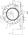
- FIG. 1 shows a device for treating a good, in particular for drying a preferably web-shaped Guts 20.
- the device comprises a housing 6.
- a drum 2 is arranged in the housing 6.
- the drum 2 is gas permeable.
- the drum 2 is permeable to gas due to the perforations 32 in the drum shell 21.
- the drum 2 is rotatable about the drum axis 28 in the direction of rotation 26.
- the drum axis 28 is mounted in the housing 6. This is not shown in the figures.
- the drum is surrounded by a treatment room 14. This is also in FIG. 2 to recognize.
- the web-shaped material 20 is introduced via a deflection roller 38 in the transport direction 40 into the treatment space 14.
- the web-shaped material 20 is arranged at least on a part of the drum shell 21.
- the web-shaped material 20 is transported in the transport direction 40.
- the web-shaped material 20 is deflected at the exit from the treatment chamber 14 by a further deflection roller 38 and further transported in the transport direction 40.
- a shielding element 30 is arranged in the peripheral region of the drum 2, in which the drum shell 21 is not covered by the web-like material.
- the shielding member 30 is disposed outside the drum 2 and therefore can be easily mounted and replaced.
- the shielding member 30 can be prevented that a gas through the drum shell in the region of the Shielding element 30 penetrates into the drum.
- the throughflow with the gaseous treatment medium or with ambient air is thus reduced and preferably completely avoided.
- a gaseous treatment medium is introduced into the treatment space 14 via a feed device 44 via a feed channel 46 and a feed opening 48.
- the gaseous treatment medium is preferably heated air.
- FIG. 2 shows the interior of the drum is closed at one end face with an end wall 19.
- an expansion space 16 is arranged on the opposite end face.
- this expansion chamber 16 is a negative pressure, whereby a negative pressure in the drum interior 18 is generated.
- the gaseous treatment medium which is arranged in the treatment space 14 is drawn through the gas-permeable web-like material 20 and the gas-permeable drum shell 21 into the interior of the drum 18. From the inside of the drum 18, the gaseous treatment medium is drawn into the expansion space 16.
- the flow direction is shown by the arrows 34.
- the gaseous treatment medium can be fed to an air treatment plant and reprocessed and heated and returned to the treatment space 14 via the feed device 44.
- the web-shaped material 20 is, characterized in that a negative pressure is applied in the drum interior 18, attracted to the drum shell 21 and can thereby be transported in the transport direction 40 with the rotation of the drum 2. Furthermore, the wet web-like material 20 dries in that the gaseous treatment medium flows through the web-shaped material 20.
- baffles 4 are arranged in the treatment room 14. Due to the baffles 4, the treatment room is in three channels 11, 12, 13, wherein the guide plates 4 are arranged such that the three channels 11, 12, 13 extend along the circumference of the drum 2. The treatment medium thus flows in the flow direction 42 within the channels 11, 12 and 13. The flow direction of the gaseous treatment medium thus runs almost parallel to the direction of rotation 26 of the drum.
- the main surfaces 5 of the guide plate 4 extend in the radial direction to the drum.
- the width of the channels 11, 12, 13 is preferably the same size.
- the width A of the channels 11, 12, 13 is the extension of the channels 11, 12, 13 in the axis-parallel direction of the drum, d. H. in a direction parallel to the axis 28 of the drum 2.
- the baffles 4 may be adjustable in the direction parallel to the axis 52.
- threaded rods 22 are arranged distributed over the circumference, which extend parallel to the drum axis 28.
- the baffles 4 are connected to nuts 24, which are each screwed onto the threaded rods 22.
- the threaded rods can be rotated by means of adjusting units 8, whereby the nuts 24 fixedly connected to the guide plates 4 move along the threaded rods 22 in the axis-parallel direction 52, whereby the guide plates 4 in the axis-parallel direction 52 are adjustable.
- the width of the channels 11, 12 and 13 can be adjusted.
- the baffles 4 may be individually or jointly adjustable. Also, the baffles may alternatively be manually adjustable.
- the baffles 4 are in the FIG. 4 in an axis-parallel direction opposite to the FIG. 2 adjusted representation adjusted.
- the width A of the channels 11, 12 and 13 is smaller than the width A of the channels 11, 12 and 13 in FIG. 2 ,
- the baffles 4 have an end edge 7.
- the front edge 7 and the baffles 4 each have a distance from the drum shell 21.
- the distance to the drum shell 21 is preferably constant along the circumference.
- the distance to the drum shell is preferably between 10 and 150 mm. Particularly advantageous is the distance 30 to 80 mm.
- the distance of the front edge 7 to the arranged on the drum shell 21 Good 20 is preferably 10 to 50 mm. These distances are optimal for avoiding currents.
- the width of the treatment chamber 14, through which the gaseous treatment medium flows, can be adjusted.
- the width of the treatment room is in the FIG. 2 indicated by D.
- the treatment chamber 14 is bounded in the direction parallel to the axis 52 by the outer guide plates 4 which are in the axis-parallel direction.
- the web-shaped Good 20 has a width B.
- the width B of the web-shaped Good 20 on the drum 2 is the extension of the web-shaped Guts 20 in the axis-parallel direction 52.
- the width of the web-shaped Guts 20 corresponds to the working width B of the drum 2.
- the width D of the treatment chamber 14 may be to the working width B of the drum 2 be adjusted.
- the width D of the treatment chamber 14 is adapted to the working width of the drum 2. This ensures that the web-shaped treatment medium is guided only in the region along the circumference of the drum 2, in which the web-shaped material 20 is arranged.
- energy can be saved in this way, since the entire gaseous treatment medium flows through the material and not unused in the region of the drum, which is not covered with the material flows through the drum.
- a perforated plate 50 is arranged in the feed channel 46.
- the feed channel 46 and the feed opening 48 have a width that runs in the axis-parallel direction 52.
- the width of the channel 46 and the feed opening 48 corresponds to the width of the treatment space 14.
- the gaseous treatment medium can be distributed over the width of the drum 2 to the treatment space 14.
- the arranged in the feed channel 46 perforated plate 50 also has a width which extends in the axis-parallel direction, which corresponds to the width of the drum 2.
- the gas permeability of the perforated plate 50 may be adjustable. Likewise, the gas permeability of the perforated plate 50 over the width of the perforated plate 50 can be adjusted differently. In this way, the volume flow of the supplied gaseous treatment medium with varying the gas permeability of the perforated plate 50 can be varied. Thus, a higher volume flow is required for a wet fleece. The fact that the volume amount can be adapted to the respective conditions, energy can be saved.
- the volume flow of the treatment medium to be supplied can be varied such that the volume flow in the edge region of the drum and thus in the edge region of the treatment chamber 14 is set to be higher in the axis-parallel direction in the middle of the drum or treatment room 14. This is more exactly in FIG. 6 shown.
- the embodiment in the FIGS. 1 to 4 also has a treatment space 14, which is bounded in the radial direction to the outside by the housing wall 9.
- the distance between the housing wall 9 and the drum shell 21 decreases in the transport direction 40 and the direction of rotation 26 of the drum 2 from.
- the distance C1, C2, C3 preferably decreases continuously.
- FIG. 5 an embodiment is shown in which the distances C1, C2, C3 are equal.
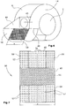
- Fig. 6 schematically shows a further embodiment for the supply of the gaseous treatment medium in the treatment chamber 14.
- the drum 2, the housing 6, the treatment chamber 14 and the feeder 44 are shown only schematically.
- the warmed gaseous treatment medium 45 is introduced into the feeder 44.
- the feed device 44 supplies the gaseous treatment medium 45 via the feed channel 46 and the feed opening 48 to the treatment space 14.
- the gaseous treatment medium 45 is preferably introduced tangentially into the treatment space 14.
- the width of the feed opening 48 seen in the axis-parallel direction is as wide as the width of the drum.
- the width of the feed channel 46 in the axis-parallel direction corresponds to the Width of the drum 2.
- a perforated plate 50 is arranged, which likewise has a width in the axis-parallel direction, which corresponds to the width of the drum 2.
- the gas permeability of the perforated plate 50 is adjustable.
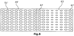
- the gas permeability of the perforated plate 50 can preferably be adjusted differently across the width X. This can be done, for example, by in FIG. 7 and 8th illustrated embodiments happen.
- a perforated plate 50 which has a first sheet metal element 49.
- the sheet metal element 49 has holes 51 distributed over the width X.
- the perforated plate distributed over the width X different sliding elements 56, 57, 58, which can be pushed in front of the respective region of the first sheet metal element 49.
- These sliding elements 56, 57, 58 also have holes 60, 62, 64. It can z. B. either the sliding elements 56 and 58 or the sliding elements 57 are pushed in front of the perforated plate.
- the diameters of the holes 60, 62, 64 of the sliding elements 56, 58 and 57 are each smaller than the holes 51 of the first sheet metal element 49.
- the holes 60, 62 and 64 of the sliding elements 56, 58 and 57 are arranged in such a way that When the slide members 56, 85, 57 are pushed in front of the perforated plate 50, the holes are arranged at the same positions as the holes 51 of the first plate member 49.
- the gaseous treatment medium must pass through the holes 51 of the first sheet metal element 49 in order to be able to flow into the treatment space 14.
- the sliding elements 56, 58 and 57 are pushed in front of the perforated plate 50, the effective diameter of the holes through which the gaseous treatment medium must pass is reduced because the holes 60, 62 and 64 are smaller than the holes 51.
- the holes 62 of the sliding elements 58 have a larger diameter than the holes 60 of the sliding elements 56.
- the sliding elements 58 are arranged in the edge region of the first sheet metal element 49. Thus, the volume flow of the perforated plate 50, when the sliding elements 56 and 58 in front of the first perforated plate element 49 are pushed higher in the edge area than in the middle area.
- the holes 64 of the sliding elements 57 are all the same size. If the sliding elements 57 are pushed in front of the first sheet-metal element 49, only the entire volume flow over the width X of the perforated plate 50 is reduced.
- a sliding element in the axis-parallel direction in front of the first sheet metal element 49 ' are pushed.
- the first sheet metal element 49 ' has holes 51 which have an elliptical shape.
- the sliding element 63 has holes with different diameters, wherein the holes 67, which are located in the axial direction in the edge region, are larger than the holes 67 in the central region of the sliding element 63.
- the holes in the edge region of the sliding element 63 have the same size as the holes 51 'of the first sheet metal element 49'.
- the holes 67 of the sliding member 63 are arranged such that the center of the respective holes 67, when the sliding member 53 is pushed in front of the first sheet member 49, are located directly in front of the centers of the holes 51 'of the first sheet member. Since the holes in the middle region of the sliding element 63 are smaller, the perforated plate 50 has a lower gas permeability in the middle region when the sliding element 63 is pushed in front of the first sheet metal element 49 '. The size of the holes 67 decreases continuously towards the center.
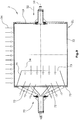
- FIG. 9 a drum 2 is shown.
- This drum 2 in the embodiments of the FIGS. 1 to 8 be used. Alternatively, this drum can be used with any other dryer.
- the drum is a gas-permeable drum 2, wherein the drum shell 21 has perforations 32. Through the drum shell can thus enter a gaseous medium. This is shown by the arrows 34.
- the end wall of the drum 2 is open, so that through this end wall, the gaseous medium can emerge from the drum interior.
- an expansion space is arranged on this side.
- the drum color of the drum is disposed within the end wall.
- the drum shade 70 is offset in the axial direction 52 of the drum outside the drum and thus offset from the end wall.
- the exit surface D3, which in FIG. 10 is shown enlarged.
- the gaseous treatment medium can only emerge from the drum through the outlet opening 72.
- a drum guide element 74 is arranged on the end face of the drum, on which the outlet opening 72 is arranged.
- This drum guide element 74 has a cone shape. However, it could also have any other shape.
- the drum guide element is disposed near the end wall 75, which has the outlet opening 72. In the present case, the drum guide element 74 is attached to the end wall 75. However, the drum guide member 74 could also be attached to the drum shell 21 near the end wall 75.
- the gaseous treatment medium which flows through the drum shell 21 near the end wall 75, must first flow into the interior of the drum in order then to reach the outlet opening 72 through the opening 73 of the drum head element. This results in the gaseous treatment medium being distributed more uniformly through the drum casing 21, since the negative pressure prevailing in the interior of the drum is distributed more uniformly over the drum casing 21. Otherwise, the negative pressure, by being generated in the expansion space adjoining the outlet opening 72, would be higher in the region of the drum shell which is arranged near the outlet opening 72.
- FIG. 11 shows a device with a first and a second treatment compartment 76 and 78, respectively.
- the treatment room 14 is the space surrounding the drum 2 in the area on which the web-shaped material 20 is arranged.
- the region on which the web-like material is not arranged, as already described, a shielding element 30 is provided.
- the treatment space 14 is in the present embodiment in FIG. 11 divided into a first and a second treatment compartment 76 and 78, respectively.
- the first treatment compartment 76 is limited in the radial direction to the outside through the housing wall 77.
- a first gaseous treatment medium 84 enters, which has a first temperature.
- the second treatment compartment 78 surrounds the drum in a second peripheral region 82.
- the second treatment compartment 78 is bounded radially outward by the housing wall 79.
- the drum 2 rotates in the direction of rotation 26, however, the peripheral areas 80 and 82 are always at the same location with respect to the building walls 77, 79.
- the web-like material is taken by the drum 2 in the direction of rotation 26 and surrounds the drum in the peripheral areas 80th and 82.
- a second gaseous treatment medium 86 flows into the second treatment chamber 78.
- the drum in the first peripheral region 80, the drum is surrounded by a first treatment medium having a first temperature
- the drum 2 in the second peripheral region 82, the drum 2 is surrounded by a second gaseous treatment medium 86 having a second temperature.
- the second peripheral region 82 is arranged behind the peripheral region 80 in the transport direction of the material.
- the first temperature of the first gaseous treatment medium 84 is preferably higher than the second temperature of the second gaseous treatment medium 86. Furthermore, the volume flow of the first gaseous treatment medium 84, which flows through the material in the first peripheral region 80, is preferably higher than the volume flow of the second gaseous treatment medium 86, which flows through the material in the second peripheral region 82, In this way, the web-like material, which first passes through the first peripheral portion 80, dried quickly. In the second peripheral region 82 it is for the drying of the material is no longer decisive whether the temperature and / or the volume flow of the second gaseous treatment medium are high.
- the temperature and / or the volumetric flow rate at which a wet product is dried have the greater influence on the drying speed the more wet the material to be dried is.
- the material is drier than in the peripheral region 80.
- the height of the temperature and / or the size of the volume flow have no great influence on the drying speed of the web-shaped Guts. Therefore, the temperature and / or the volume flow of the second gaseous treatment medium 86 may be less than the first temperature and / or the volume flow of the first gaseous treatment medium 84. In this way, energy is saved.
- the second temperature and / or the volume flow of the second gaseous treatment medium 86 may be higher than the first temperature and / or the volume flow of the first gaseous treatment medium 84.
- FIG. 12 another embodiment is arranged with a first and a second treatment chamber 76 and 78, respectively.
- This embodiment differs in that the second treatment compartment surrounds not only the drum 2 in the peripheral portion 82, but also the first treatment compartment on the side of the treatment compartment which is not adjacent to the drum 2.
- the second treatment compartment 78 thus surrounds the housing wall 77 of the first treatment compartment.
- the second gaseous treatment medium 86 which is introduced into the second treatment compartment 78, first passes past the housing wall 77 of the first treatment compartment before it enters the region of the second treatment compartment 78, which partially surrounds the drum 2.
- the gaseous treatment medium 86 is preheated by the waste heat of the first treatment compartment 76.
- the drum 2 may be divided in the interior 18 in a first and a second drum compartment space 90, 92, wherein the first drum compartment space in the first Peripheral region 80 of the drum is arranged and the second drum part space is arranged in the second peripheral region 82, so that the first gaseous treatment medium 84, which passes through the drum shell 21 in the drum interior 18, enters the first drum part space 90 and the second gaseous treatment medium 86, which passes through the drum shell, enters the second part of the drum compartment.
- the respective first and second gaseous treatment medium 84, 86 which has respectively entered the first and the second drum compartment, can each be recycled and heated separately, and fresh air can be supplied and then re-enter the first or second treatment compartment.
- the first and second treatment partitions may each have channels as they are in the FIGS. 1 to 5 have been described.
- a third or fourth treatment compartment can be provided, each surrounding the drum in a peripheral region, which follows the first and second peripheral region in the transport direction of the goods.
- gaseous treatment media can be introduced at different temperatures.
Landscapes
- Engineering & Computer Science (AREA)
- Mechanical Engineering (AREA)
- General Engineering & Computer Science (AREA)
- Textile Engineering (AREA)
- Health & Medical Sciences (AREA)
- Life Sciences & Earth Sciences (AREA)
- Molecular Biology (AREA)
- Treatment Of Fiber Materials (AREA)
- Drying Of Solid Materials (AREA)
Applications Claiming Priority (3)
| Application Number | Priority Date | Filing Date | Title |
|---|---|---|---|
| DE102011113835A DE102011113835A1 (de) | 2011-09-21 | 2011-09-21 | Vorrichtung zum Behandeln von einem Gut, insbesondere zum Trocknen eines vorzugsweise bahnförmigen Guts |
| PCT/EP2012/067831 WO2013041429A1 (fr) | 2011-09-21 | 2012-09-12 | Dispositif de traitement d'un article, destiné en particulier à sécher un article de préférence en forme de bande |
| EP12756520.8A EP2758737B1 (fr) | 2011-09-21 | 2012-09-12 | Dispositif de traitement d'un article, destiné en particulier à sécher un article de préférence en forme de bande |
Related Parent Applications (2)
| Application Number | Title | Priority Date | Filing Date |
|---|---|---|---|
| EP12756520.8A Division EP2758737B1 (fr) | 2011-09-21 | 2012-09-12 | Dispositif de traitement d'un article, destiné en particulier à sécher un article de préférence en forme de bande |
| EP12756520.8A Division-Into EP2758737B1 (fr) | 2011-09-21 | 2012-09-12 | Dispositif de traitement d'un article, destiné en particulier à sécher un article de préférence en forme de bande |
Publications (3)
| Publication Number | Publication Date |
|---|---|
| EP3258201A2 true EP3258201A2 (fr) | 2017-12-20 |
| EP3258201A3 EP3258201A3 (fr) | 2018-02-28 |
| EP3258201B1 EP3258201B1 (fr) | 2019-06-19 |
Family
ID=46826558
Family Applications (3)
| Application Number | Title | Priority Date | Filing Date |
|---|---|---|---|
| EP17165712.5A Not-in-force EP3258200B1 (fr) | 2011-09-21 | 2012-09-12 | Dispositif de traitement d'un produit, en particulier destiné à sécher un produit de préférence sous forme de bande |
| EP12756520.8A Not-in-force EP2758737B1 (fr) | 2011-09-21 | 2012-09-12 | Dispositif de traitement d'un article, destiné en particulier à sécher un article de préférence en forme de bande |
| EP17165770.3A Not-in-force EP3258201B1 (fr) | 2011-09-21 | 2012-09-12 | Dispositif de traitement d'un produit, en particulier destiné à sécher un produit de préférence sous forme de bande |
Family Applications Before (2)
| Application Number | Title | Priority Date | Filing Date |
|---|---|---|---|
| EP17165712.5A Not-in-force EP3258200B1 (fr) | 2011-09-21 | 2012-09-12 | Dispositif de traitement d'un produit, en particulier destiné à sécher un produit de préférence sous forme de bande |
| EP12756520.8A Not-in-force EP2758737B1 (fr) | 2011-09-21 | 2012-09-12 | Dispositif de traitement d'un article, destiné en particulier à sécher un article de préférence en forme de bande |
Country Status (6)
| Country | Link |
|---|---|
| US (1) | US20140215848A1 (fr) |
| EP (3) | EP3258200B1 (fr) |
| CN (1) | CN103827615B (fr) |
| DE (1) | DE102011113835A1 (fr) |
| IN (1) | IN2014CN02142A (fr) |
| WO (1) | WO2013041429A1 (fr) |
Families Citing this family (9)
| Publication number | Priority date | Publication date | Assignee | Title |
|---|---|---|---|---|
| DE102014102119A1 (de) * | 2014-02-19 | 2015-08-20 | TRüTZSCHLER GMBH & CO. KG | Vorrichtung zum Trocknen einer textilen Warenbahn |
| FR3033875B1 (fr) * | 2015-03-17 | 2021-06-18 | Andritz Perfojet Sas | Tambour metallique, notamment pour un secheur |
| CN106288678A (zh) * | 2015-06-09 | 2017-01-04 | 漳州灿坤实业有限公司 | 食物烘干机 |
| DE102015118157A1 (de) | 2015-10-23 | 2017-04-27 | Trützschler GmbH & Co Kommanditgesellschaft | Vorrichtung zum thermischen Behandeln einer textilen Warenbahn |
| DE102016109413A1 (de) * | 2016-05-23 | 2017-11-23 | Trützschler GmbH + Co KG Textilmaschinenfabrik | Trockner für eine textile Warenbahn mit einer verbesserten Heißluftzufuhr |
| DE102016110117A1 (de) | 2016-06-01 | 2017-12-07 | TRüTZSCHLER GMBH & CO. KG | Vorrichtung zur Wärmebehandlung einer textilen Warenbahn, insbesondere ein Trockner oder Thermobonder |
| CN110081670A (zh) * | 2019-03-27 | 2019-08-02 | 安徽巨创化纤科技有限公司 | 一种滤布用的烘干装置 |
| CN111876886B (zh) * | 2020-07-31 | 2021-12-10 | 吉林省参达塑业有限公司 | 一种具有烘干功能的纺织机 |
| CN113210381B (zh) * | 2021-04-14 | 2022-08-05 | 东软威特曼生物科技(沈阳)有限公司 | 用于清洗生化分析仪中比色杯的清洗组件及生化分析仪 |
Family Cites Families (22)
| Publication number | Priority date | Publication date | Assignee | Title |
|---|---|---|---|---|
| DD19485A (fr) * | ||||
| FR1160178A (fr) * | 1956-07-12 | 1958-07-08 | Séchoir continu pour fibres textiles | |
| DE1278950B (de) * | 1959-04-14 | 1968-09-26 | Fleissner G M B H | Abdeckplattenanordnung an einer Vorrichtung zum Trocknen oder Nassbehandeln von behandlungsmitteldurchlaessigem oder -undurchlaessigem Gut |
| US3140157A (en) * | 1959-03-26 | 1964-07-07 | Fleissner Gmbh Fa | Drying apparatus |
| DE1779873C3 (de) * | 1959-05-08 | 1974-06-06 | Fleissner Gmbh, 6073 Egelsbach | Siebtrommeltrockner. Ausscheidung aus: 1404540 |
| US3122428A (en) * | 1959-05-08 | 1964-02-25 | Fleissner Gmbh | Drying apparatus having variable pressure suction zones |
| DE1604775A1 (de) * | 1965-09-24 | 1971-01-14 | Patentdienst Anstalt F | Vorrichtung zum Behandeln,insbesondere Trocknen von Guetern aller Art |
| DE1460518A1 (de) * | 1965-09-25 | 1969-04-10 | Patentdienst Anstalt F | Vorrichtung zum Behandeln,insbesondere Trocknen,von Guetern aller Art |
| BE728060A (fr) * | 1968-02-10 | 1969-08-07 | ||
| DE1900496C3 (de) * | 1969-01-07 | 1978-11-09 | Vepa Ag, Riehen B. Basel (Schweiz) | Vorrichtung zum Behandeln von durchlässigen Gütern |
| GB1251154A (fr) * | 1968-02-14 | 1971-10-27 | ||
| DE1729499A1 (de) * | 1968-02-14 | 1972-02-24 | Vepa Ag | Siebtrommeltrockner |
| DE2755790A1 (de) * | 1977-12-14 | 1979-06-28 | Frederick D Helversen | Trockenvorrichtung zum trocknen einer papier- bzw. fasermaterialbahn |
| US4364185A (en) * | 1981-04-13 | 1982-12-21 | Ingersoll-Rand Company | System for drying wet, porous webs |
| DE4022336A1 (de) * | 1990-07-13 | 1992-01-16 | Fleissner Maschf Ag | Vorrichtung zum durchstroemenden behandeln von bahnfoermigem gut |
| US5937538A (en) * | 1996-05-21 | 1999-08-17 | Fort James Corporation | Through air dryer apparatus for drying webs |
| US5915813A (en) * | 1996-05-21 | 1999-06-29 | Fort James Corporation | Apparatus and method for drying a wet web and modifying the moisture profile thereof |
| US6631566B2 (en) * | 2000-09-18 | 2003-10-14 | Kimberly-Clark Worldwide, Inc. | Method of drying a web |
| AT412484B (de) * | 2003-04-29 | 2005-03-25 | Andritz Ag Maschf | Vorrichtung zum trocknen einer papierbahn |
| US7225558B2 (en) * | 2004-07-30 | 2007-06-05 | Metso Paper Usa, Inc. | Cross-machine flow and profile control for through-air devices treating permeable webs |
| US8176650B2 (en) * | 2005-12-13 | 2012-05-15 | Kimberly-Clark Worldwide, Inc. | Method for warming up or cooling down a through-air dryer |
| DE102009016019A1 (de) * | 2009-04-02 | 2010-10-07 | Fleissner Gmbh | Trockner für textile Warenbahnen |
-
2011
- 2011-09-21 DE DE102011113835A patent/DE102011113835A1/de not_active Withdrawn
-
2012
- 2012-09-12 EP EP17165712.5A patent/EP3258200B1/fr not_active Not-in-force
- 2012-09-12 EP EP12756520.8A patent/EP2758737B1/fr not_active Not-in-force
- 2012-09-12 US US14/346,102 patent/US20140215848A1/en not_active Abandoned
- 2012-09-12 EP EP17165770.3A patent/EP3258201B1/fr not_active Not-in-force
- 2012-09-12 CN CN201280046272.4A patent/CN103827615B/zh not_active Expired - Fee Related
- 2012-09-12 WO PCT/EP2012/067831 patent/WO2013041429A1/fr not_active Ceased
-
2014
- 2014-03-20 IN IN2142CHN2014 patent/IN2014CN02142A/en unknown
Non-Patent Citations (1)
| Title |
|---|
| None |
Also Published As
| Publication number | Publication date |
|---|---|
| DE102011113835A1 (de) | 2013-03-21 |
| US20140215848A1 (en) | 2014-08-07 |
| EP3258201B1 (fr) | 2019-06-19 |
| EP2758737B1 (fr) | 2017-11-08 |
| CN103827615A (zh) | 2014-05-28 |
| WO2013041429A1 (fr) | 2013-03-28 |
| EP3258200A1 (fr) | 2017-12-20 |
| EP2758737A1 (fr) | 2014-07-30 |
| IN2014CN02142A (fr) | 2015-05-29 |
| EP3258200B1 (fr) | 2019-03-06 |
| CN103827615B (zh) | 2016-03-16 |
| EP3258201A3 (fr) | 2018-02-28 |
Similar Documents
| Publication | Publication Date | Title |
|---|---|---|
| EP2758737B1 (fr) | Dispositif de traitement d'un article, destiné en particulier à sécher un article de préférence en forme de bande | |
| DE2053284C3 (de) | Trocknungsvorrichtung für Materialbahnen mit einem Schallerzeuger | |
| EP0465769B1 (fr) | Dispositif pour le traitement par traversée de fluide d'un matériau en bande | |
| EP2758736B1 (fr) | Système de chauffage destiné à chauffer un milieu de traitement gazeux pour un séchoir | |
| EP3720716A1 (fr) | Procédé pour le séchage d'un substrat, module de séchage pour la mise en uvre du procédé ainsi que système de séchage | |
| EP3165861B1 (fr) | Dispositif de traitement traversant de matériaux en bande | |
| DE69835149T2 (de) | Vorrichtung zur Behandlung von durchlässigen oder halbdurchlässigen Bahnen | |
| WO2017071862A1 (fr) | Dispositif et procédé de traitement thermique d'une bande de matière textile | |
| DE2155222B2 (de) | Drehbarer Trockenzylinder | |
| EP2735830B1 (fr) | Dispositif et procédé de traitement d'un produit de préférence en forme de bande à l'aide d'un moyen de traitement gazeux | |
| DE2322113A1 (de) | Trocknungsanlage zur behandlung von materialbahnen | |
| DE1460709C3 (de) | Siebtrommeltrockner Ausscheidung aus 1281992 | |
| AT412484B (de) | Vorrichtung zum trocknen einer papierbahn | |
| DE2229905A1 (de) | Vorrichtung zur behandlung von bahnen aus stoff, papier od.dgl | |
| EP0141227B1 (fr) | Séchoir vertical | |
| DE1604785C3 (de) | Siebwalzenvorrichtung z.B. zum Wärmebehandeln luftdurchlässiger Güter | |
| DE1604872A1 (de) | Verfahren und Vorrichtung zum Behandeln von nassem bzw. feuchtem Gut | |
| DE1635122A1 (de) | Vorrichtung zur Behandlung von Guetern mit gas- oder dampffoermigen Medien | |
| DE2647198C3 (de) | Trommeltrockner mit einer in einem Gehäuse um eine Achse rotierbaren Trommel | |
| DE3148321A1 (de) | "vorrichtung zum waermebehandeln von horizontal gefuehrten, bahnfoermigen guetern." | |
| EP1258691B1 (fr) | Dispositif pour sécher des particules | |
| DE1410118B2 (de) | Verfahren und vorrichtung zum kontinuierlichen faerben mittels sattdampf | |
| CH421034A (de) | Trommeltrockner für luftdurchlässige Materialien | |
| DE20221831U1 (de) | Vorrichtung zur Führung von Luft | |
| DE1497431A1 (de) | Fotokopiergeraet mit einer Einrichtung zur Kuehlung des Belichtungszylinders |
Legal Events
| Date | Code | Title | Description |
|---|---|---|---|
| PUAI | Public reference made under article 153(3) epc to a published international application that has entered the european phase |
Free format text: ORIGINAL CODE: 0009012 |
|
| STAA | Information on the status of an ep patent application or granted ep patent |
Free format text: STATUS: THE APPLICATION HAS BEEN PUBLISHED |
|
| AC | Divisional application: reference to earlier application |
Ref document number: 2758737 Country of ref document: EP Kind code of ref document: P |
|
| AK | Designated contracting states |
Kind code of ref document: A2 Designated state(s): AL AT BE BG CH CY CZ DE DK EE ES FI FR GB GR HR HU IE IS IT LI LT LU LV MC MK MT NL NO PL PT RO RS SE SI SK SM TR |
|
| PUAL | Search report despatched |
Free format text: ORIGINAL CODE: 0009013 |
|
| AK | Designated contracting states |
Kind code of ref document: A3 Designated state(s): AL AT BE BG CH CY CZ DE DK EE ES FI FR GB GR HR HU IE IS IT LI LT LU LV MC MK MT NL NO PL PT RO RS SE SI SK SM TR |
|
| RIC1 | Information provided on ipc code assigned before grant |
Ipc: F26B 21/12 20060101ALI20180125BHEP Ipc: F26B 13/16 20060101AFI20180125BHEP |
|
| STAA | Information on the status of an ep patent application or granted ep patent |
Free format text: STATUS: REQUEST FOR EXAMINATION WAS MADE |
|
| 17P | Request for examination filed |
Effective date: 20180828 |
|
| RBV | Designated contracting states (corrected) |
Designated state(s): AL AT BE BG CH CY CZ DE DK EE ES FI FR GB GR HR HU IE IS IT LI LT LU LV MC MK MT NL NO PL PT RO RS SE SI SK SM TR |
|
| GRAP | Despatch of communication of intention to grant a patent |
Free format text: ORIGINAL CODE: EPIDOSNIGR1 |
|
| STAA | Information on the status of an ep patent application or granted ep patent |
Free format text: STATUS: GRANT OF PATENT IS INTENDED |
|
| RIC1 | Information provided on ipc code assigned before grant |
Ipc: F26B 13/16 20060101AFI20181207BHEP Ipc: F26B 21/12 20060101ALI20181207BHEP |
|
| INTG | Intention to grant announced |
Effective date: 20190107 |
|
| GRAS | Grant fee paid |
Free format text: ORIGINAL CODE: EPIDOSNIGR3 |
|
| GRAA | (expected) grant |
Free format text: ORIGINAL CODE: 0009210 |
|
| STAA | Information on the status of an ep patent application or granted ep patent |
Free format text: STATUS: THE PATENT HAS BEEN GRANTED |
|
| AC | Divisional application: reference to earlier application |
Ref document number: 2758737 Country of ref document: EP Kind code of ref document: P |
|
| AK | Designated contracting states |
Kind code of ref document: B1 Designated state(s): AL AT BE BG CH CY CZ DE DK EE ES FI FR GB GR HR HU IE IS IT LI LT LU LV MC MK MT NL NO PL PT RO RS SE SI SK SM TR |
|
| REG | Reference to a national code |
Ref country code: GB Ref legal event code: FG4D Free format text: NOT ENGLISH |
|
| REG | Reference to a national code |
Ref country code: CH Ref legal event code: EP |
|
| REG | Reference to a national code |
Ref country code: IE Ref legal event code: FG4D Free format text: LANGUAGE OF EP DOCUMENT: GERMAN |
|
| REG | Reference to a national code |
Ref country code: DE Ref legal event code: R096 Ref document number: 502012014952 Country of ref document: DE |
|
| REG | Reference to a national code |
Ref country code: AT Ref legal event code: REF Ref document number: 1146048 Country of ref document: AT Kind code of ref document: T Effective date: 20190715 |
|
| REG | Reference to a national code |
Ref country code: NL Ref legal event code: MP Effective date: 20190619 |
|
| PG25 | Lapsed in a contracting state [announced via postgrant information from national office to epo] |
Ref country code: SE Free format text: LAPSE BECAUSE OF FAILURE TO SUBMIT A TRANSLATION OF THE DESCRIPTION OR TO PAY THE FEE WITHIN THE PRESCRIBED TIME-LIMIT Effective date: 20190619 Ref country code: AL Free format text: LAPSE BECAUSE OF FAILURE TO SUBMIT A TRANSLATION OF THE DESCRIPTION OR TO PAY THE FEE WITHIN THE PRESCRIBED TIME-LIMIT Effective date: 20190619 Ref country code: LT Free format text: LAPSE BECAUSE OF FAILURE TO SUBMIT A TRANSLATION OF THE DESCRIPTION OR TO PAY THE FEE WITHIN THE PRESCRIBED TIME-LIMIT Effective date: 20190619 Ref country code: HR Free format text: LAPSE BECAUSE OF FAILURE TO SUBMIT A TRANSLATION OF THE DESCRIPTION OR TO PAY THE FEE WITHIN THE PRESCRIBED TIME-LIMIT Effective date: 20190619 Ref country code: FI Free format text: LAPSE BECAUSE OF FAILURE TO SUBMIT A TRANSLATION OF THE DESCRIPTION OR TO PAY THE FEE WITHIN THE PRESCRIBED TIME-LIMIT Effective date: 20190619 Ref country code: NO Free format text: LAPSE BECAUSE OF FAILURE TO SUBMIT A TRANSLATION OF THE DESCRIPTION OR TO PAY THE FEE WITHIN THE PRESCRIBED TIME-LIMIT Effective date: 20190919 |
|
| REG | Reference to a national code |
Ref country code: LT Ref legal event code: MG4D |
|
| PG25 | Lapsed in a contracting state [announced via postgrant information from national office to epo] |
Ref country code: RS Free format text: LAPSE BECAUSE OF FAILURE TO SUBMIT A TRANSLATION OF THE DESCRIPTION OR TO PAY THE FEE WITHIN THE PRESCRIBED TIME-LIMIT Effective date: 20190619 Ref country code: BG Free format text: LAPSE BECAUSE OF FAILURE TO SUBMIT A TRANSLATION OF THE DESCRIPTION OR TO PAY THE FEE WITHIN THE PRESCRIBED TIME-LIMIT Effective date: 20190919 Ref country code: LV Free format text: LAPSE BECAUSE OF FAILURE TO SUBMIT A TRANSLATION OF THE DESCRIPTION OR TO PAY THE FEE WITHIN THE PRESCRIBED TIME-LIMIT Effective date: 20190619 Ref country code: GR Free format text: LAPSE BECAUSE OF FAILURE TO SUBMIT A TRANSLATION OF THE DESCRIPTION OR TO PAY THE FEE WITHIN THE PRESCRIBED TIME-LIMIT Effective date: 20190920 |
|
| PG25 | Lapsed in a contracting state [announced via postgrant information from national office to epo] |
Ref country code: NL Free format text: LAPSE BECAUSE OF FAILURE TO SUBMIT A TRANSLATION OF THE DESCRIPTION OR TO PAY THE FEE WITHIN THE PRESCRIBED TIME-LIMIT Effective date: 20190619 Ref country code: SK Free format text: LAPSE BECAUSE OF FAILURE TO SUBMIT A TRANSLATION OF THE DESCRIPTION OR TO PAY THE FEE WITHIN THE PRESCRIBED TIME-LIMIT Effective date: 20190619 Ref country code: RO Free format text: LAPSE BECAUSE OF FAILURE TO SUBMIT A TRANSLATION OF THE DESCRIPTION OR TO PAY THE FEE WITHIN THE PRESCRIBED TIME-LIMIT Effective date: 20190619 Ref country code: CZ Free format text: LAPSE BECAUSE OF FAILURE TO SUBMIT A TRANSLATION OF THE DESCRIPTION OR TO PAY THE FEE WITHIN THE PRESCRIBED TIME-LIMIT Effective date: 20190619 Ref country code: PT Free format text: LAPSE BECAUSE OF FAILURE TO SUBMIT A TRANSLATION OF THE DESCRIPTION OR TO PAY THE FEE WITHIN THE PRESCRIBED TIME-LIMIT Effective date: 20191021 Ref country code: EE Free format text: LAPSE BECAUSE OF FAILURE TO SUBMIT A TRANSLATION OF THE DESCRIPTION OR TO PAY THE FEE WITHIN THE PRESCRIBED TIME-LIMIT Effective date: 20190619 |
|
| PG25 | Lapsed in a contracting state [announced via postgrant information from national office to epo] |
Ref country code: ES Free format text: LAPSE BECAUSE OF FAILURE TO SUBMIT A TRANSLATION OF THE DESCRIPTION OR TO PAY THE FEE WITHIN THE PRESCRIBED TIME-LIMIT Effective date: 20190619 Ref country code: IS Free format text: LAPSE BECAUSE OF FAILURE TO SUBMIT A TRANSLATION OF THE DESCRIPTION OR TO PAY THE FEE WITHIN THE PRESCRIBED TIME-LIMIT Effective date: 20191019 Ref country code: SM Free format text: LAPSE BECAUSE OF FAILURE TO SUBMIT A TRANSLATION OF THE DESCRIPTION OR TO PAY THE FEE WITHIN THE PRESCRIBED TIME-LIMIT Effective date: 20190619 |
|
| PG25 | Lapsed in a contracting state [announced via postgrant information from national office to epo] |
Ref country code: TR Free format text: LAPSE BECAUSE OF FAILURE TO SUBMIT A TRANSLATION OF THE DESCRIPTION OR TO PAY THE FEE WITHIN THE PRESCRIBED TIME-LIMIT Effective date: 20190619 |
|
| PG25 | Lapsed in a contracting state [announced via postgrant information from national office to epo] |
Ref country code: PL Free format text: LAPSE BECAUSE OF FAILURE TO SUBMIT A TRANSLATION OF THE DESCRIPTION OR TO PAY THE FEE WITHIN THE PRESCRIBED TIME-LIMIT Effective date: 20190619 Ref country code: DK Free format text: LAPSE BECAUSE OF FAILURE TO SUBMIT A TRANSLATION OF THE DESCRIPTION OR TO PAY THE FEE WITHIN THE PRESCRIBED TIME-LIMIT Effective date: 20190619 |
|
| PG25 | Lapsed in a contracting state [announced via postgrant information from national office to epo] |
Ref country code: MC Free format text: LAPSE BECAUSE OF FAILURE TO SUBMIT A TRANSLATION OF THE DESCRIPTION OR TO PAY THE FEE WITHIN THE PRESCRIBED TIME-LIMIT Effective date: 20190619 Ref country code: IS Free format text: LAPSE BECAUSE OF FAILURE TO SUBMIT A TRANSLATION OF THE DESCRIPTION OR TO PAY THE FEE WITHIN THE PRESCRIBED TIME-LIMIT Effective date: 20200224 |
|
| REG | Reference to a national code |
Ref country code: CH Ref legal event code: PL |
|
| REG | Reference to a national code |
Ref country code: DE Ref legal event code: R097 Ref document number: 502012014952 Country of ref document: DE |
|
| PLBE | No opposition filed within time limit |
Free format text: ORIGINAL CODE: 0009261 |
|
| STAA | Information on the status of an ep patent application or granted ep patent |
Free format text: STATUS: NO OPPOSITION FILED WITHIN TIME LIMIT |
|
| PG2D | Information on lapse in contracting state deleted |
Ref country code: IS |
|
| PG25 | Lapsed in a contracting state [announced via postgrant information from national office to epo] |
Ref country code: LI Free format text: LAPSE BECAUSE OF NON-PAYMENT OF DUE FEES Effective date: 20190930 Ref country code: LU Free format text: LAPSE BECAUSE OF NON-PAYMENT OF DUE FEES Effective date: 20190912 Ref country code: CH Free format text: LAPSE BECAUSE OF NON-PAYMENT OF DUE FEES Effective date: 20190930 Ref country code: IE Free format text: LAPSE BECAUSE OF NON-PAYMENT OF DUE FEES Effective date: 20190912 |
|
| 26N | No opposition filed |
Effective date: 20200603 |
|
| REG | Reference to a national code |
Ref country code: BE Ref legal event code: MM Effective date: 20190930 |
|
| PG25 | Lapsed in a contracting state [announced via postgrant information from national office to epo] |
Ref country code: SI Free format text: LAPSE BECAUSE OF FAILURE TO SUBMIT A TRANSLATION OF THE DESCRIPTION OR TO PAY THE FEE WITHIN THE PRESCRIBED TIME-LIMIT Effective date: 20190619 Ref country code: BE Free format text: LAPSE BECAUSE OF NON-PAYMENT OF DUE FEES Effective date: 20190930 |
|
| GBPC | Gb: european patent ceased through non-payment of renewal fee |
Effective date: 20190919 |
|
| PG25 | Lapsed in a contracting state [announced via postgrant information from national office to epo] |
Ref country code: GB Free format text: LAPSE BECAUSE OF NON-PAYMENT OF DUE FEES Effective date: 20190919 |
|
| PGFP | Annual fee paid to national office [announced via postgrant information from national office to epo] |
Ref country code: DE Payment date: 20200925 Year of fee payment: 9 Ref country code: FR Payment date: 20200914 Year of fee payment: 9 |
|
| PGFP | Annual fee paid to national office [announced via postgrant information from national office to epo] |
Ref country code: AT Payment date: 20200921 Year of fee payment: 9 Ref country code: IT Payment date: 20200922 Year of fee payment: 9 |
|
| PG25 | Lapsed in a contracting state [announced via postgrant information from national office to epo] |
Ref country code: CY Free format text: LAPSE BECAUSE OF FAILURE TO SUBMIT A TRANSLATION OF THE DESCRIPTION OR TO PAY THE FEE WITHIN THE PRESCRIBED TIME-LIMIT Effective date: 20190619 |
|
| PG25 | Lapsed in a contracting state [announced via postgrant information from national office to epo] |
Ref country code: MT Free format text: LAPSE BECAUSE OF FAILURE TO SUBMIT A TRANSLATION OF THE DESCRIPTION OR TO PAY THE FEE WITHIN THE PRESCRIBED TIME-LIMIT Effective date: 20190619 Ref country code: HU Free format text: LAPSE BECAUSE OF FAILURE TO SUBMIT A TRANSLATION OF THE DESCRIPTION OR TO PAY THE FEE WITHIN THE PRESCRIBED TIME-LIMIT; INVALID AB INITIO Effective date: 20120912 |
|
| REG | Reference to a national code |
Ref country code: DE Ref legal event code: R119 Ref document number: 502012014952 Country of ref document: DE |
|
| REG | Reference to a national code |
Ref country code: AT Ref legal event code: MM01 Ref document number: 1146048 Country of ref document: AT Kind code of ref document: T Effective date: 20210912 |
|
| PG25 | Lapsed in a contracting state [announced via postgrant information from national office to epo] |
Ref country code: MK Free format text: LAPSE BECAUSE OF FAILURE TO SUBMIT A TRANSLATION OF THE DESCRIPTION OR TO PAY THE FEE WITHIN THE PRESCRIBED TIME-LIMIT Effective date: 20190619 |
|
| PG25 | Lapsed in a contracting state [announced via postgrant information from national office to epo] |
Ref country code: FR Free format text: LAPSE BECAUSE OF NON-PAYMENT OF DUE FEES Effective date: 20210930 Ref country code: DE Free format text: LAPSE BECAUSE OF NON-PAYMENT OF DUE FEES Effective date: 20220401 |
|
| PG25 | Lapsed in a contracting state [announced via postgrant information from national office to epo] |
Ref country code: AT Free format text: LAPSE BECAUSE OF NON-PAYMENT OF DUE FEES Effective date: 20210912 |
|
| PG25 | Lapsed in a contracting state [announced via postgrant information from national office to epo] |
Ref country code: IT Free format text: LAPSE BECAUSE OF NON-PAYMENT OF DUE FEES Effective date: 20210912 |