EP3258202B1 - Wärmetauscher, wärmetauschermontagevorrichtung und wärmetauschermontageverfahren - Google Patents
Wärmetauscher, wärmetauschermontagevorrichtung und wärmetauschermontageverfahren Download PDFInfo
- Publication number
- EP3258202B1 EP3258202B1 EP16749174.5A EP16749174A EP3258202B1 EP 3258202 B1 EP3258202 B1 EP 3258202B1 EP 16749174 A EP16749174 A EP 16749174A EP 3258202 B1 EP3258202 B1 EP 3258202B1
- Authority
- EP
- European Patent Office
- Prior art keywords
- tubes
- heat exchanger
- tube
- laminate
- laminate body
- Prior art date
- Legal status (The legal status is an assumption and is not a legal conclusion. Google has not performed a legal analysis and makes no representation as to the accuracy of the status listed.)
- Active
Links
Images




Classifications
-
- F—MECHANICAL ENGINEERING; LIGHTING; HEATING; WEAPONS; BLASTING
- F28—HEAT EXCHANGE IN GENERAL
- F28D—HEAT-EXCHANGE APPARATUS, NOT PROVIDED FOR IN ANOTHER SUBCLASS, IN WHICH THE HEAT-EXCHANGE MEDIA DO NOT COME INTO DIRECT CONTACT
- F28D1/00—Heat-exchange apparatus having stationary conduit assemblies for one heat-exchange medium only, the media being in contact with different sides of the conduit wall, in which the other heat-exchange medium is a large body of fluid, e.g. domestic or motor car radiators
- F28D1/02—Heat-exchange apparatus having stationary conduit assemblies for one heat-exchange medium only, the media being in contact with different sides of the conduit wall, in which the other heat-exchange medium is a large body of fluid, e.g. domestic or motor car radiators with heat-exchange conduits immersed in the body of fluid
- F28D1/04—Heat-exchange apparatus having stationary conduit assemblies for one heat-exchange medium only, the media being in contact with different sides of the conduit wall, in which the other heat-exchange medium is a large body of fluid, e.g. domestic or motor car radiators with heat-exchange conduits immersed in the body of fluid with tubular conduits
- F28D1/053—Heat-exchange apparatus having stationary conduit assemblies for one heat-exchange medium only, the media being in contact with different sides of the conduit wall, in which the other heat-exchange medium is a large body of fluid, e.g. domestic or motor car radiators with heat-exchange conduits immersed in the body of fluid with tubular conduits the conduits being straight
- F28D1/05316—Assemblies of conduits connected to common headers, e.g. core type radiators
- F28D1/05333—Assemblies of conduits connected to common headers, e.g. core type radiators with multiple rows of conduits or with multi-channel conduits
-
- B—PERFORMING OPERATIONS; TRANSPORTING
- B23—MACHINE TOOLS; METAL-WORKING NOT OTHERWISE PROVIDED FOR
- B23P—METAL-WORKING NOT OTHERWISE PROVIDED FOR; COMBINED OPERATIONS; UNIVERSAL MACHINE TOOLS
- B23P15/00—Making specific metal objects by operations not covered by a single other subclass or a group in this subclass
- B23P15/26—Making specific metal objects by operations not covered by a single other subclass or a group in this subclass heat exchangers or the like
-
- B—PERFORMING OPERATIONS; TRANSPORTING
- B23—MACHINE TOOLS; METAL-WORKING NOT OTHERWISE PROVIDED FOR
- B23P—METAL-WORKING NOT OTHERWISE PROVIDED FOR; COMBINED OPERATIONS; UNIVERSAL MACHINE TOOLS
- B23P21/00—Machines for assembling a multiplicity of different parts to compose units, with or without preceding or subsequent working of such parts, e.g. with program control
-
- F—MECHANICAL ENGINEERING; LIGHTING; HEATING; WEAPONS; BLASTING
- F28—HEAT EXCHANGE IN GENERAL
- F28D—HEAT-EXCHANGE APPARATUS, NOT PROVIDED FOR IN ANOTHER SUBCLASS, IN WHICH THE HEAT-EXCHANGE MEDIA DO NOT COME INTO DIRECT CONTACT
- F28D1/00—Heat-exchange apparatus having stationary conduit assemblies for one heat-exchange medium only, the media being in contact with different sides of the conduit wall, in which the other heat-exchange medium is a large body of fluid, e.g. domestic or motor car radiators
- F28D1/02—Heat-exchange apparatus having stationary conduit assemblies for one heat-exchange medium only, the media being in contact with different sides of the conduit wall, in which the other heat-exchange medium is a large body of fluid, e.g. domestic or motor car radiators with heat-exchange conduits immersed in the body of fluid
- F28D1/04—Heat-exchange apparatus having stationary conduit assemblies for one heat-exchange medium only, the media being in contact with different sides of the conduit wall, in which the other heat-exchange medium is a large body of fluid, e.g. domestic or motor car radiators with heat-exchange conduits immersed in the body of fluid with tubular conduits
- F28D1/053—Heat-exchange apparatus having stationary conduit assemblies for one heat-exchange medium only, the media being in contact with different sides of the conduit wall, in which the other heat-exchange medium is a large body of fluid, e.g. domestic or motor car radiators with heat-exchange conduits immersed in the body of fluid with tubular conduits the conduits being straight
- F28D1/0535—Heat-exchange apparatus having stationary conduit assemblies for one heat-exchange medium only, the media being in contact with different sides of the conduit wall, in which the other heat-exchange medium is a large body of fluid, e.g. domestic or motor car radiators with heat-exchange conduits immersed in the body of fluid with tubular conduits the conduits being straight the conduits having a non-circular cross-section
- F28D1/05366—Assemblies of conduits connected to common headers, e.g. core type radiators
-
- F—MECHANICAL ENGINEERING; LIGHTING; HEATING; WEAPONS; BLASTING
- F28—HEAT EXCHANGE IN GENERAL
- F28F—DETAILS OF HEAT-EXCHANGE AND HEAT-TRANSFER APPARATUS, OF GENERAL APPLICATION
- F28F9/00—Casings; Header boxes; Auxiliary supports for elements; Auxiliary members within casings
- F28F9/02—Header boxes; End plates
- F28F9/0229—Double end plates; Single end plates with hollow spaces
-
- F—MECHANICAL ENGINEERING; LIGHTING; HEATING; WEAPONS; BLASTING
- F28—HEAT EXCHANGE IN GENERAL
- F28F—DETAILS OF HEAT-EXCHANGE AND HEAT-TRANSFER APPARATUS, OF GENERAL APPLICATION
- F28F9/00—Casings; Header boxes; Auxiliary supports for elements; Auxiliary members within casings
- F28F9/02—Header boxes; End plates
- F28F9/04—Arrangements for sealing elements into header boxes or end plates
- F28F9/06—Arrangements for sealing elements into header boxes or end plates by dismountable joints
- F28F9/14—Arrangements for sealing elements into header boxes or end plates by dismountable joints by force-joining
-
- F—MECHANICAL ENGINEERING; LIGHTING; HEATING; WEAPONS; BLASTING
- F28—HEAT EXCHANGE IN GENERAL
- F28F—DETAILS OF HEAT-EXCHANGE AND HEAT-TRANSFER APPARATUS, OF GENERAL APPLICATION
- F28F9/00—Casings; Header boxes; Auxiliary supports for elements; Auxiliary members within casings
- F28F9/02—Header boxes; End plates
- F28F2009/0285—Other particular headers or end plates
- F28F2009/0292—Other particular headers or end plates with fins
Definitions
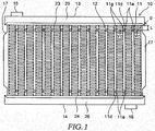
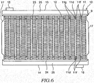
- the heat exchanger 10 includes a plurality of tubes 11 in which the internal medium flows, corrugated fins 12 arranged alternately with respective tubes 11, right and left reinforcements 17 disposed in such a way as to be aligned with both ends of a laminate body of respective tubes 11 and fins 12, and upper and lower tanks 13 and 14 to which opening ends 11d of respective tubes 11 are connected.
- the flat tube 11 can be formed by bending a metal plate, such as an aluminum plate, into a cylindrical shape.
- a metal plate such as an aluminum plate
- the tube 11 is not limited to a specific type and may be formed by extruding a molten metal material into a cylindrical shape.
- each fin 12 is hermetically in contact with neighboring tubes 11.
- a predetermined number of tubes 11 and fins 12 laminated alternately with each other is referred to as "laminate body 18".
- the "laminate direction" is the direction along which the tubes 11 and the fins 12 are aligned.
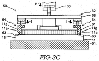
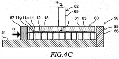
- the assembling apparatus 50 includes a table 51, a laminate-direction compressing unit 55, a thickness-direction compressing unit 60, and a tank assembling unit (not illustrated).
- the laminate-direction compressing unit 55 is a mechanism which of compresses the laminate body 18 placed on the table 51 in the laminate direction.
- the laminate-direction compressing unit 55 includes a fixing portion 56 fixed to the table 51, a movable portion 57 supported by the table 51 so as to be movable in the laminate direction, and an actuator (not illustrated) that can move the movable portion 57.
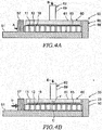
- the driving mechanism 62 of the leveling plate 61 includes a guide rod 69 (refer to FIGS. 4A to 4C ) that supports the leveling plate 61 so as to be movable in the vertical direction, a support base 65, and an actuator 66 that raises or lowers the support base 65 to move the leveling plate 61.
- a hydraulic cylinder is adoptable as the actuator 66.
- the driving mechanisms 64 of the holding portions 63 include a pair of guide portions 67 each supporting the corresponding holding portion 63 so as to be movable in the vertical direction with respect to the support base 65, and a pair of actuators 68 for raising and lowering corresponding guide portions 67 to move the holding portions 63.
- a hydraulic cylinder is adoptable as the actuator 68.
- the lamination process includes placing the laminate body 18 constituted by a predetermined number of tubes 11 and fins 12 arranged respectively on the table 51, and causing the driving mechanism 62 of the thickness-direction compressing unit 60 to lower the support base 65 toward the table 51 so that the laminate body 18 is pressed in the thickness direction by the leveling plate 61 and each holding portion 63 with a driving force B (refer to FIG. 3A ).
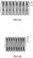
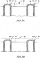
- Each holding portion 63 is held at a position on the same plane (on the horizontal plane) as the leveling plate 61 and presses the laminate body 18 together with the leveling plate 61. In this case, no plastic deformation occurs in the pressing portion 11g of the tube 11 pressed by each holding portion 63 (refer to FIG. 5A ).
- the lamination process may include moving the holding portion 63 upward away from the laminate body 18 and pressing the laminate body 18 by only the leveling plate 61.
- FIG. 7 is a configuration diagram illustrating an operation of an assembling apparatus 150 according to a comparative example.
- a thickness-direction compressing unit 160 of the assembling apparatus 150 does not have any holding portion and compresses the laminate body 18 by using only a leveling plate 161 in the thickness direction.
- the thickness-direction compressing unit 160 is subjected to a frictional force M acting from the laminate body 18.
- the frictional force M is large, the frictional force M deforms a guide rod 169 supporting the leveling plate 161 so as to be inclined by an angle ⁇ , while the leveling plate 161 is displaced in the laminate direction by a distance N and inclines with respect to the table 51. Accordingly, if the orientation of the leveling plate 161 changes, undesirable positional deviation in which some of the tubes 11 are lifted off the table 51 may occur.
- the driving force E required for the driving mechanism 62 to press the laminate body 18 against the table 51 is set to be greater than the driving force B in the lamination process and appropriate in smoothly moving the tubes 11 and the fins 12 pressed by the movable portion 57 of the laminate-direction compressing unit 55 toward the fixing portion 56.
- the driving force E of the driving mechanism 62 can be controlled based on a stroke amount required for the driving mechanism 62 to move the leveling plate 61 toward the table 51, instead of setting the driving force E of the driving mechanism 62.
- the interval between the table 51 and the leveling plate 61 is set to be slightly smaller than the thickness of the laminate body 18.
- each holding portion 63 is separated from the laminate body 18 (refer to FIG. 5B ) and the pressing force with which the holding portion 63 presses the laminate body 18 becomes zero. Therefore, when the laminate-direction compressing unit 55 compresses the laminate body 18 in the laminate direction, a frictional force C that the driving mechanism 62 of the thickness-direction compressing unit 60 receives from the laminate body 18 is suppressed to be smaller. As a result, the guide rod 69 supporting the leveling plate 61 or the like is suppressed from deflecting, and the orientation of the leveling plate 61 can be held to face the table 51 in parallel with each other. The orientation of the leveling plate 61 as mentioned above is maintained in the main compression process can prevent the positional deviation in which some of the tubes 11 are lifted off the table 51 can be prevented from occurring.
- the laminate-direction compressing unit 55 compresses the laminate body 18 with a driving force G in the laminate direction (refer to FIG. 4C ), while the actuator 66 of the driving mechanism 62 presses the laminate body 18 by the leveling plate 61 with a driving force H in the thickness direction.
- the actuator 68 of the driving mechanism 64 presses the laminate body 18 by the holding portion 63 with a driving force I in the thickness direction (refer to FIG. 3C ).
- the surface 11b of the pressing portion 11g of the tube 11 curved into an arc shape is pressed by the holding portion 63 with driving force I and, as a result, the concave portion 11a is formed.
- the concave portion 11a has a pair of step portions 11c opposed to each other. Each step portion 11c extends in a direction (lateral direction) perpendicular to the longitudinal direction of the tube 11.
- the heat treatment is performed to cause the cladding layers applied beforehand to the surfaces of the tubes 11, the fins 12, and the tank plates 23 and 24 to melt and braze the constituent components together, thereby forming the heat exchanger core 9.
- the tank bodies 25 and 26 are united with the tank plates 23 and 24 to complete the heat exchanger 10.
- the present embodiment provides the assembling method including the lamination process for laminating respective tubes 11, the main compression process for compressing respective tubes 11 in the laminate direction, and the assembling process for connecting the tanks 13 and 14 with respective tubes 11 in a state where the tubes 11 are held and pressed by the holding portion 63 for holding each tube 11 in the vicinity of the opening end 11d of respective tubes 11 compressed in the laminate direction.
- each tube 11 In the assembling process, the load or the stroke amount required for pressing the holding portion 63 against each tube 51 is appropriately set so that each tube 11 can return to the original surface shape without causing any plastic deformation even when the surface is deflected by the pressing of the holding portion 63 (refer to FIGS. 3C and 4C ). As a result, the pressing portion 11g of each tube 11 is formed with the pressed mark portion 11f whose surface roughness is partly variable without forming any concave portion by pressing the holding portion 63.
- the configuration is not limited to the above-mentioned example.
- the assembling process can be configured such that any pressed mark does not remain on the surface of each tube 11 by appropriately setting the load or the stroke amount required for the holding portion 63 to press each tube 11.
- the leveling plate 61 and the holding portion 63 are configured to move vertically with respect to the table 51 so as to press the laminate body 18.
- the configuration is not limited to the above-mentioned example.
- a rotating mechanism using a hinge is adoptable to press the laminate body 18 from an inclined direction.
Landscapes
- Engineering & Computer Science (AREA)
- Mechanical Engineering (AREA)
- Physics & Mathematics (AREA)
- Thermal Sciences (AREA)
- General Engineering & Computer Science (AREA)
- Heat-Exchange Devices With Radiators And Conduit Assemblies (AREA)
- Details Of Heat-Exchange And Heat-Transfer (AREA)
Claims (13)
- Wärmetauscher (10), der einen Schichtkörper (18) enthält, der durch eine Vielzahl abwechselnd geschichteter Röhren (11) und Rippen (12) gebildet wird, wobei die geschichteten Röhren ein offenes Ende (11d) haben, mit dem ein Behälter (13) verbunden ist, und
der Schichtkörper (18) einen Press-Abschnitt (11g) enthält, der sich in der Nähe des offenen Endes (11d) jeder Röhre (11) befindet, wobei der Schichtkörper (18) von dem Press-Abschnitt (11g) gehalten wird, wenn der Behälter (13) mit dem offenen Ende (11d) der Röhren (11) verbunden ist, und
der Press-Abschnitt (11g) sich an dem Schichtkörper (18) an zwei Abschnitten befindet, die voneinander in einer Längsrichtung der Röhre (11) getrennt sind, dadurch gekennzeichnet, dass der Press-Abschnitt (11g) eine an einer Oberfläche der Röhre (11) auszubildende Press-Markierung enthält,
wobei die Press-Markierung ein an der Oberfläche der Röhre (11) vertiefter konkaver Abschnitt (11a) ist. - Wärmetauscher (10) nach Anspruch 1, wobei der Press-Abschnitt (11g) nur an der Röhre (11) vorhanden ist.
- Wärmetauscher (10) nach Anspruch 1 oder 2, wobei die Größe der Rippe (12) in einer Dicken-Richtung kleiner ist als die Größe der Röhre (11) in der Dicken-Richtung,
die Rippen (12) an Positionen angeordnet sind, die auf ein Ende der Röhre (11) in der Dicken-Richtung zu versetzt sind, und
der Press-Abschnitt (11g) sich an dem anderen Ende der Röhren (11) in der Dicken-Richtung befindet. - Wärmetauscher (10) nach Anspruch 3, wobei die Rippen (12) und das eine Ende der Röhren (11) in der gleichen Ebene angeordnet sind.
- Wärmetauscher (10) nach einem der Ansprüche 1 bis 4, wobei der konkave Abschnitt (11a) eine Tiefe hat, die kleiner ist als eine Differenz zwischen der Größe der Rippe (12) in der Dicken-Richtung und der Größe der Röhre (11) in der Dicken-Richtung.
- Wärmetauscher (10) nach einem der Ansprüche 1 bis 5, wobei der Press-Abschnitt (11g) an einer Position ausgebildet ist, die von dem Behälter (13) in einer Längsrichtung der Röhre (11) getrennt ist.
- Vorrichtung (50) zum Montieren eines Wärmetauschers, mit der ein Wärmetauscher (10) montiert wird, der einen Schichtkörper (18) enthält, der durch eine Vielzahl abwechselnd geschichteter Röhren (11) und Rippen (12) gebildet wird, wobei die geschichteten Röhren (11) ein offenes Ende (11d) haben, mit dem ein Behälter (13) verbunden ist, und die Vorrichtung (50) zum Montieren umfasst:
einen Tisch (51), auf dem jeweilige Röhren (11) und Rippen (12) geschichtet werden;eine Einheit (55) zum Zusammendrücken in Schichtungs-Richtung, die zum Zusammendrücken des auf dem Tisch (51) geschichteten Schichtkörpers (18) in einer Schichtungs-Richtung eingerichtet ist; sowieeine Einheit (60) zum Zusammendrücken in Dicken-Richtung, die zum Zusammendrücken des Schichtkörpers (18) in einer Dicken-Richtung senkrecht zu dem Tisch (51) eingerichtet ist, wobeidie Einheit (60) zum Zusammendrücken in Dicken-Richtung einen Halte-Abschnitt (63) enthält, der so eingerichtet ist, dass er den in der Schichtungs-Richtung durch die Einheit (55) zum Zusammendrücken in Schichtungs-Richtung zusammengedrückten Schichtkörper (18) in der Nähe des offenen Endes (11d) der Vielzahl von Röhren (11) an den Tisch (51) presst, undder Halte-Abschnitt (63) so eingerichtet ist, dass er den Schichtkörper (18) an zwei Abschnitten hält, die voneinander in einer Längsrichtung der Vielzahl von Röhren (11) getrennt sind, wenn der Behälter (13) mit der Vielzahl von Röhren (11) verbunden ist, dadurch gekennzeichnet, dassdie Einheit (60) zum Zusammendrücken in Dicken-Richtung so eingerichtet ist, dass sie Press-Markierungen an Oberflächen der Vielzahl von Röhren (11) mit dem Halte-Abschnitt (63) ausbildet,wobei die Press-Markierung ein an der Oberfläche der Röhre (11) vertiefter konkaver Abschnitt (11a) ist. - Vorrichtung (50) zum Montieren eines Wärmetauschers nach Anspruch 7, wobei der Halte-Abschnitt (63) nur zum Halten der Röhren (11) eingerichtet ist.
- Vorrichtung (50) zum Montieren eines Wärmetauschers nach Anspruch 7 oder 8, wobei die Größe der Rippe (12) in der Dicken-Richtung kleiner ist als die Größe der Röhre (11) in der Dicken-Richtung,
die Röhren (11) und die Rippen (12) in Kontakt mit dem Tisch (51) sind, und
die Press-Markierungen durch den Halte-Abschnitt (63) an den anderen Enden der Rippen (12) ausgebildet werden, die sich an der Seite befinden, die Enden der Rippen (12) gegenüberliegt, die in Kontakt mit dem Tisch (51) sind. - Vorrichtung (50) zum Montieren eines Wärmetauschers nach Anspruch 9, wobei die Einheit (60) zum Zusammendrücken in Dicken-Richtung eine Ausricht-Platte (61) enthält, die auf den Halte-Abschnitt (63) ausgerichtet und zum Pressen der Vielzahl von Röhren (11) an den Tisch (51) eingerichtet ist, und
die Ausricht-Platte (61) so eingerichtet ist, dass sie die Vielzahl von Röhren (11) in einem Zustand in der Dicken-Richtung zusammendrückt, in dem der Halte-Abschnitt (63) von der Vielzahl von Röhren (11) getrennt ist. - Verfahren zum Montieren eines Wärmetauschers, mit dem ein Wärmetauscher (10) montiert wird, der einen Schichtkörper (18) enthält, der durch eine Vielzahl abwechselnd geschichteter Röhren (11) und Rippen (12) gebildet wird, wobei die geschichteten Röhren (11) ein offenes Ende (11b) haben, mit dem ein Behälter (13) verbunden ist, und das Verfahren umfasst:einen Schichtungs-Prozess zum Schichten der Vielzahl von Röhren (11) und Rippen (12);einen Haupt-Zusammendrück-Prozess zum Zusammendrücken des Schichtkörpers (18) in einer Schichtungs-Richtung;einen Zusammenbau-Prozess zum Verbinden des Behälters (13) mit der Vielzahl von Röhren (11) in einem Zustand, in dem der Schichtkörper (18) von einem Halte-Abschnitt (63) an zwei voneinander in einer Längsrichtung der Vielzahl von Röhren (11) getrennten Abschnitten gehalten und gepresst wird, um den Schichtkörper (18) in der Nähe des offenen Endes (11d) der Vielzahl von Röhren (11) in der Schichtungs-Richtung zusammengedrückt zu halten, dadurch gekennzeichnet, dassder Zusammenbau-Prozess Ausbilden von Press-Markierungen an Oberflächen der Vielzahl von Röhren (11) mit dem Halte-Abschnitt (63) einschließt,wobei die Press-Markierung ein an der Oberfläche der Röhre (11) vertiefter konkaver Abschnitt (11a) ist.
- Verfahren zum Montieren eines Wärmetauschers nach Anspruch 11, wobei der Halte-Abschnitt (63) bei dem Zusammenbau-Prozess nur die Röhren (11) hält.
- Verfahren zum Montieren eines Wärmetauschers nach Anspruch 11 oder 12, wobei die Größe der Rippe (12) in einer Dicken-Richtung kleiner ist als die Größe der Röhre (11) in der Dicken-Richtung,
der Schichtungs-Prozess einschließt, dass die Rippen (12) an Positionen angeordnet werden, die auf Enden der Röhren (11) in der Dicken-Richtung zu versetzt sind, und
die Press-Markierungen durch den Halte-Abschnitt (63) bei dem Zusammenbau-Prozess an den anderen Enden der Röhren (11) ausgebildet werden, die sich an der Seite befinden, die den einen Enden der Röhren (11) in der Dicken-Richtung gegenüberliegt.
Applications Claiming Priority (3)
| Application Number | Priority Date | Filing Date | Title |
|---|---|---|---|
| JP2015025527 | 2015-02-12 | ||
| JP2016008445A JP2016153718A (ja) | 2015-02-12 | 2016-01-20 | 熱交換器、熱交換器の組み立て装置、及び熱交換器の組み立て方法 |
| PCT/JP2016/053555 WO2016129530A1 (ja) | 2015-02-12 | 2016-02-05 | 熱交換器、熱交換器の組立装置、及び熱交換器の組立方法 |
Publications (3)
| Publication Number | Publication Date |
|---|---|
| EP3258202A1 EP3258202A1 (de) | 2017-12-20 |
| EP3258202A4 EP3258202A4 (de) | 2018-02-21 |
| EP3258202B1 true EP3258202B1 (de) | 2019-05-01 |
Family
ID=56761100
Family Applications (1)
| Application Number | Title | Priority Date | Filing Date |
|---|---|---|---|
| EP16749174.5A Active EP3258202B1 (de) | 2015-02-12 | 2016-02-05 | Wärmetauscher, wärmetauschermontagevorrichtung und wärmetauschermontageverfahren |
Country Status (4)
| Country | Link |
|---|---|
| US (1) | US20180031325A1 (de) |
| EP (1) | EP3258202B1 (de) |
| JP (1) | JP2016153718A (de) |
| CN (1) | CN107250702A (de) |
Families Citing this family (2)
| Publication number | Priority date | Publication date | Assignee | Title |
|---|---|---|---|---|
| CN113785168B (zh) * | 2019-05-14 | 2023-11-03 | 三菱电机株式会社 | 热交换器及制冷循环装置 |
| CN114131301A (zh) * | 2021-11-08 | 2022-03-04 | 格力电器(洛阳)有限公司 | 空调外机侧板装配系统 |
Family Cites Families (7)
| Publication number | Priority date | Publication date | Assignee | Title |
|---|---|---|---|---|
| JPH04354631A (ja) * | 1991-05-29 | 1992-12-09 | Toshiba Corp | パイプ挿入装置 |
| WO1998009124A1 (en) * | 1996-08-29 | 1998-03-05 | Zexel Corporation | Heat exchanger |
| JP4094806B2 (ja) * | 2000-12-28 | 2008-06-04 | カルソニックカンセイ株式会社 | 熱交換器の製造方法 |
| JP2005513403A (ja) * | 2001-12-21 | 2005-05-12 | ベール ゲーエムベーハー ウント コー カーゲー | 特に自動車用の熱交換器 |
| AU2004221537A1 (en) * | 2003-03-18 | 2004-09-30 | Showa Denko K.K. | Tube blank correcting member for use in temporarily assembling heat exchanger, and apparatus for and method of temporaily assembling heat exchanger |
| JP5527169B2 (ja) * | 2010-11-11 | 2014-06-18 | 株式会社デンソー | 熱交換器用チューブ |
| JP2014237186A (ja) * | 2013-06-07 | 2014-12-18 | カルソニックカンセイ株式会社 | 熱交換器の組立装置及び組立方法 |
-
2016
- 2016-01-20 JP JP2016008445A patent/JP2016153718A/ja not_active Withdrawn
- 2016-02-05 EP EP16749174.5A patent/EP3258202B1/de active Active
- 2016-02-05 US US15/550,430 patent/US20180031325A1/en not_active Abandoned
- 2016-02-05 CN CN201680010101.4A patent/CN107250702A/zh active Pending
Non-Patent Citations (1)
| Title |
|---|
| None * |
Also Published As
| Publication number | Publication date |
|---|---|
| CN107250702A (zh) | 2017-10-13 |
| JP2016153718A (ja) | 2016-08-25 |
| US20180031325A1 (en) | 2018-02-01 |
| EP3258202A4 (de) | 2018-02-21 |
| EP3258202A1 (de) | 2017-12-20 |
Similar Documents
| Publication | Publication Date | Title |
|---|---|---|
| KR102297779B1 (ko) | 열교환기용 핀으로의 편평 튜브 삽입 장치 | |
| CN102164692B (zh) | 封闭结构构件的制造方法、冲压成形装置和封闭结构构件 | |
| CN102164691B (zh) | 封闭结构构件的制造方法、冲压成形装置和封闭结构构件 | |
| KR102277669B1 (ko) | 열교환기용 핀으로의 편평 튜브 삽입 장치 | |
| JP6473464B2 (ja) | 扁平チューブ用フィンの取り出し装置 | |
| CN103801627B (zh) | 用于热交换器翅片的制造装置 | |
| KR101910782B1 (ko) | 프레스 성형품의 제조 방법 및 프레스 장치 | |
| US20050241360A1 (en) | Apparatus and method for forming shaped articles | |
| EP3258202B1 (de) | Wärmetauscher, wärmetauschermontagevorrichtung und wärmetauschermontageverfahren | |
| US10551134B2 (en) | Header for a heat exchanger, and method of making the same | |
| EP2434245B1 (de) | Montageverfahren für Wärmetauscher | |
| US5186239A (en) | Heat exchanger with thermal stress relieving zone | |
| US20110203341A1 (en) | Corrugated fin manufacturing apparatus | |
| CN113859370B (zh) | 一种模具 | |
| CN101918157B (zh) | 用于冲压成形可变形材料的组件和方法 | |
| EP3985342A1 (de) | Wärmetauscher und wärmetauscherherstellungsverfahren | |
| JPH06154924A (ja) | プレス加工方法 | |
| JP2014237186A (ja) | 熱交換器の組立装置及び組立方法 | |
| WO2016129530A1 (ja) | 熱交換器、熱交換器の組立装置、及び熱交換器の組立方法 | |
| JP7265141B2 (ja) | プレス成形用ブランク、プレス成形用ブランクの製造方法、連結成形品の製造方法、プレス成形品の製造方法、プレス成形用金型、およびプレス成形装置 | |
| JP5701073B2 (ja) | 熱交換器コアの仮組立装置およびその仮組立方法 | |
| KR101100118B1 (ko) | 열교환기용 매니폴드 및 그 제조방법 | |
| KR100225149B1 (ko) | 열교환기에 응력 감소 존을 만드는 장치 | |
| CN219664937U (zh) | 紧凑自制斜楔运用结构 | |
| CN220659732U (zh) | 一种行程调整工装及车身生产线 |
Legal Events
| Date | Code | Title | Description |
|---|---|---|---|
| STAA | Information on the status of an ep patent application or granted ep patent |
Free format text: STATUS: THE INTERNATIONAL PUBLICATION HAS BEEN MADE |
|
| PUAI | Public reference made under article 153(3) epc to a published international application that has entered the european phase |
Free format text: ORIGINAL CODE: 0009012 |
|
| STAA | Information on the status of an ep patent application or granted ep patent |
Free format text: STATUS: REQUEST FOR EXAMINATION WAS MADE |
|
| 17P | Request for examination filed |
Effective date: 20170821 |
|
| AK | Designated contracting states |
Kind code of ref document: A1 Designated state(s): AL AT BE BG CH CY CZ DE DK EE ES FI FR GB GR HR HU IE IS IT LI LT LU LV MC MK MT NL NO PL PT RO RS SE SI SK SM TR |
|
| AX | Request for extension of the european patent |
Extension state: BA ME |
|
| A4 | Supplementary search report drawn up and despatched |
Effective date: 20180122 |
|
| RIC1 | Information provided on ipc code assigned before grant |
Ipc: F28D 1/053 20060101AFI20180116BHEP Ipc: B23P 21/00 20060101ALI20180116BHEP Ipc: F28F 9/02 20060101ALI20180116BHEP Ipc: B23P 15/26 20060101ALI20180116BHEP |
|
| DAV | Request for validation of the european patent (deleted) | ||
| DAX | Request for extension of the european patent (deleted) | ||
| GRAP | Despatch of communication of intention to grant a patent |
Free format text: ORIGINAL CODE: EPIDOSNIGR1 |
|
| STAA | Information on the status of an ep patent application or granted ep patent |
Free format text: STATUS: GRANT OF PATENT IS INTENDED |
|
| RIC1 | Information provided on ipc code assigned before grant |
Ipc: F28F 9/14 20060101ALI20181019BHEP Ipc: B23P 21/00 20060101ALI20181019BHEP Ipc: F28F 9/02 20060101ALI20181019BHEP Ipc: B23P 15/26 20060101ALI20181019BHEP Ipc: F28D 1/053 20060101AFI20181019BHEP |
|
| INTG | Intention to grant announced |
Effective date: 20181115 |
|
| GRAS | Grant fee paid |
Free format text: ORIGINAL CODE: EPIDOSNIGR3 |
|
| GRAA | (expected) grant |
Free format text: ORIGINAL CODE: 0009210 |
|
| STAA | Information on the status of an ep patent application or granted ep patent |
Free format text: STATUS: THE PATENT HAS BEEN GRANTED |
|
| AK | Designated contracting states |
Kind code of ref document: B1 Designated state(s): AL AT BE BG CH CY CZ DE DK EE ES FI FR GB GR HR HU IE IS IT LI LT LU LV MC MK MT NL NO PL PT RO RS SE SI SK SM TR |
|
| REG | Reference to a national code |
Ref country code: GB Ref legal event code: FG4D |
|
| REG | Reference to a national code |
Ref country code: CH Ref legal event code: EP Ref country code: AT Ref legal event code: REF Ref document number: 1127506 Country of ref document: AT Kind code of ref document: T Effective date: 20190515 |
|
| REG | Reference to a national code |
Ref country code: DE Ref legal event code: R096 Ref document number: 602016013318 Country of ref document: DE |
|
| REG | Reference to a national code |
Ref country code: IE Ref legal event code: FG4D |
|
| REG | Reference to a national code |
Ref country code: NL Ref legal event code: MP Effective date: 20190501 |
|
| REG | Reference to a national code |
Ref country code: LT Ref legal event code: MG4D |
|
| PG25 | Lapsed in a contracting state [announced via postgrant information from national office to epo] |
Ref country code: PT Free format text: LAPSE BECAUSE OF FAILURE TO SUBMIT A TRANSLATION OF THE DESCRIPTION OR TO PAY THE FEE WITHIN THE PRESCRIBED TIME-LIMIT Effective date: 20190901 Ref country code: AL Free format text: LAPSE BECAUSE OF FAILURE TO SUBMIT A TRANSLATION OF THE DESCRIPTION OR TO PAY THE FEE WITHIN THE PRESCRIBED TIME-LIMIT Effective date: 20190501 Ref country code: ES Free format text: LAPSE BECAUSE OF FAILURE TO SUBMIT A TRANSLATION OF THE DESCRIPTION OR TO PAY THE FEE WITHIN THE PRESCRIBED TIME-LIMIT Effective date: 20190501 Ref country code: HR Free format text: LAPSE BECAUSE OF FAILURE TO SUBMIT A TRANSLATION OF THE DESCRIPTION OR TO PAY THE FEE WITHIN THE PRESCRIBED TIME-LIMIT Effective date: 20190501 Ref country code: SE Free format text: LAPSE BECAUSE OF FAILURE TO SUBMIT A TRANSLATION OF THE DESCRIPTION OR TO PAY THE FEE WITHIN THE PRESCRIBED TIME-LIMIT Effective date: 20190501 Ref country code: NO Free format text: LAPSE BECAUSE OF FAILURE TO SUBMIT A TRANSLATION OF THE DESCRIPTION OR TO PAY THE FEE WITHIN THE PRESCRIBED TIME-LIMIT Effective date: 20190801 Ref country code: FI Free format text: LAPSE BECAUSE OF FAILURE TO SUBMIT A TRANSLATION OF THE DESCRIPTION OR TO PAY THE FEE WITHIN THE PRESCRIBED TIME-LIMIT Effective date: 20190501 Ref country code: LT Free format text: LAPSE BECAUSE OF FAILURE TO SUBMIT A TRANSLATION OF THE DESCRIPTION OR TO PAY THE FEE WITHIN THE PRESCRIBED TIME-LIMIT Effective date: 20190501 Ref country code: NL Free format text: LAPSE BECAUSE OF FAILURE TO SUBMIT A TRANSLATION OF THE DESCRIPTION OR TO PAY THE FEE WITHIN THE PRESCRIBED TIME-LIMIT Effective date: 20190501 |
|
| PG25 | Lapsed in a contracting state [announced via postgrant information from national office to epo] |
Ref country code: RS Free format text: LAPSE BECAUSE OF FAILURE TO SUBMIT A TRANSLATION OF THE DESCRIPTION OR TO PAY THE FEE WITHIN THE PRESCRIBED TIME-LIMIT Effective date: 20190501 Ref country code: LV Free format text: LAPSE BECAUSE OF FAILURE TO SUBMIT A TRANSLATION OF THE DESCRIPTION OR TO PAY THE FEE WITHIN THE PRESCRIBED TIME-LIMIT Effective date: 20190501 Ref country code: BG Free format text: LAPSE BECAUSE OF FAILURE TO SUBMIT A TRANSLATION OF THE DESCRIPTION OR TO PAY THE FEE WITHIN THE PRESCRIBED TIME-LIMIT Effective date: 20190801 Ref country code: GR Free format text: LAPSE BECAUSE OF FAILURE TO SUBMIT A TRANSLATION OF THE DESCRIPTION OR TO PAY THE FEE WITHIN THE PRESCRIBED TIME-LIMIT Effective date: 20190802 |
|
| REG | Reference to a national code |
Ref country code: AT Ref legal event code: MK05 Ref document number: 1127506 Country of ref document: AT Kind code of ref document: T Effective date: 20190501 |
|
| PG25 | Lapsed in a contracting state [announced via postgrant information from national office to epo] |
Ref country code: IS Free format text: LAPSE BECAUSE OF FAILURE TO SUBMIT A TRANSLATION OF THE DESCRIPTION OR TO PAY THE FEE WITHIN THE PRESCRIBED TIME-LIMIT Effective date: 20190901 |
|
| PG25 | Lapsed in a contracting state [announced via postgrant information from national office to epo] |
Ref country code: AT Free format text: LAPSE BECAUSE OF FAILURE TO SUBMIT A TRANSLATION OF THE DESCRIPTION OR TO PAY THE FEE WITHIN THE PRESCRIBED TIME-LIMIT Effective date: 20190501 Ref country code: EE Free format text: LAPSE BECAUSE OF FAILURE TO SUBMIT A TRANSLATION OF THE DESCRIPTION OR TO PAY THE FEE WITHIN THE PRESCRIBED TIME-LIMIT Effective date: 20190501 Ref country code: DK Free format text: LAPSE BECAUSE OF FAILURE TO SUBMIT A TRANSLATION OF THE DESCRIPTION OR TO PAY THE FEE WITHIN THE PRESCRIBED TIME-LIMIT Effective date: 20190501 Ref country code: SK Free format text: LAPSE BECAUSE OF FAILURE TO SUBMIT A TRANSLATION OF THE DESCRIPTION OR TO PAY THE FEE WITHIN THE PRESCRIBED TIME-LIMIT Effective date: 20190501 Ref country code: RO Free format text: LAPSE BECAUSE OF FAILURE TO SUBMIT A TRANSLATION OF THE DESCRIPTION OR TO PAY THE FEE WITHIN THE PRESCRIBED TIME-LIMIT Effective date: 20190501 Ref country code: CZ Free format text: LAPSE BECAUSE OF FAILURE TO SUBMIT A TRANSLATION OF THE DESCRIPTION OR TO PAY THE FEE WITHIN THE PRESCRIBED TIME-LIMIT Effective date: 20190501 |
|
| REG | Reference to a national code |
Ref country code: DE Ref legal event code: R097 Ref document number: 602016013318 Country of ref document: DE |
|
| PG25 | Lapsed in a contracting state [announced via postgrant information from national office to epo] |
Ref country code: SM Free format text: LAPSE BECAUSE OF FAILURE TO SUBMIT A TRANSLATION OF THE DESCRIPTION OR TO PAY THE FEE WITHIN THE PRESCRIBED TIME-LIMIT Effective date: 20190501 Ref country code: IT Free format text: LAPSE BECAUSE OF FAILURE TO SUBMIT A TRANSLATION OF THE DESCRIPTION OR TO PAY THE FEE WITHIN THE PRESCRIBED TIME-LIMIT Effective date: 20190501 |
|
| PLBE | No opposition filed within time limit |
Free format text: ORIGINAL CODE: 0009261 |
|
| STAA | Information on the status of an ep patent application or granted ep patent |
Free format text: STATUS: NO OPPOSITION FILED WITHIN TIME LIMIT |
|
| PG25 | Lapsed in a contracting state [announced via postgrant information from national office to epo] |
Ref country code: TR Free format text: LAPSE BECAUSE OF FAILURE TO SUBMIT A TRANSLATION OF THE DESCRIPTION OR TO PAY THE FEE WITHIN THE PRESCRIBED TIME-LIMIT Effective date: 20190501 |
|
| 26N | No opposition filed |
Effective date: 20200204 |
|
| PG25 | Lapsed in a contracting state [announced via postgrant information from national office to epo] |
Ref country code: PL Free format text: LAPSE BECAUSE OF FAILURE TO SUBMIT A TRANSLATION OF THE DESCRIPTION OR TO PAY THE FEE WITHIN THE PRESCRIBED TIME-LIMIT Effective date: 20190501 |
|
| PG25 | Lapsed in a contracting state [announced via postgrant information from national office to epo] |
Ref country code: SI Free format text: LAPSE BECAUSE OF FAILURE TO SUBMIT A TRANSLATION OF THE DESCRIPTION OR TO PAY THE FEE WITHIN THE PRESCRIBED TIME-LIMIT Effective date: 20190501 |
|
| REG | Reference to a national code |
Ref country code: DE Ref legal event code: R119 Ref document number: 602016013318 Country of ref document: DE |
|
| REG | Reference to a national code |
Ref country code: CH Ref legal event code: PL |
|
| GBPC | Gb: european patent ceased through non-payment of renewal fee |
Effective date: 20200205 |
|
| REG | Reference to a national code |
Ref country code: BE Ref legal event code: MM Effective date: 20200229 |
|
| PG25 | Lapsed in a contracting state [announced via postgrant information from national office to epo] |
Ref country code: MC Free format text: LAPSE BECAUSE OF FAILURE TO SUBMIT A TRANSLATION OF THE DESCRIPTION OR TO PAY THE FEE WITHIN THE PRESCRIBED TIME-LIMIT Effective date: 20190501 Ref country code: LU Free format text: LAPSE BECAUSE OF NON-PAYMENT OF DUE FEES Effective date: 20200205 |
|
| PG25 | Lapsed in a contracting state [announced via postgrant information from national office to epo] |
Ref country code: LI Free format text: LAPSE BECAUSE OF NON-PAYMENT OF DUE FEES Effective date: 20200229 Ref country code: CH Free format text: LAPSE BECAUSE OF NON-PAYMENT OF DUE FEES Effective date: 20200229 |
|
| PG25 | Lapsed in a contracting state [announced via postgrant information from national office to epo] |
Ref country code: FR Free format text: LAPSE BECAUSE OF NON-PAYMENT OF DUE FEES Effective date: 20200229 Ref country code: IE Free format text: LAPSE BECAUSE OF NON-PAYMENT OF DUE FEES Effective date: 20200205 Ref country code: DE Free format text: LAPSE BECAUSE OF NON-PAYMENT OF DUE FEES Effective date: 20200901 Ref country code: GB Free format text: LAPSE BECAUSE OF NON-PAYMENT OF DUE FEES Effective date: 20200205 |
|
| PG25 | Lapsed in a contracting state [announced via postgrant information from national office to epo] |
Ref country code: BE Free format text: LAPSE BECAUSE OF NON-PAYMENT OF DUE FEES Effective date: 20200229 |
|
| PG25 | Lapsed in a contracting state [announced via postgrant information from national office to epo] |
Ref country code: MT Free format text: LAPSE BECAUSE OF FAILURE TO SUBMIT A TRANSLATION OF THE DESCRIPTION OR TO PAY THE FEE WITHIN THE PRESCRIBED TIME-LIMIT Effective date: 20190501 Ref country code: CY Free format text: LAPSE BECAUSE OF FAILURE TO SUBMIT A TRANSLATION OF THE DESCRIPTION OR TO PAY THE FEE WITHIN THE PRESCRIBED TIME-LIMIT Effective date: 20190501 |
|
| PG25 | Lapsed in a contracting state [announced via postgrant information from national office to epo] |
Ref country code: MK Free format text: LAPSE BECAUSE OF FAILURE TO SUBMIT A TRANSLATION OF THE DESCRIPTION OR TO PAY THE FEE WITHIN THE PRESCRIBED TIME-LIMIT Effective date: 20190501 |