EP3258296B1 - Barriere de micro-ondes de reflexion - Google Patents
Barriere de micro-ondes de reflexion Download PDFInfo
- Publication number
- EP3258296B1 EP3258296B1 EP16174419.8A EP16174419A EP3258296B1 EP 3258296 B1 EP3258296 B1 EP 3258296B1 EP 16174419 A EP16174419 A EP 16174419A EP 3258296 B1 EP3258296 B1 EP 3258296B1
- Authority
- EP
- European Patent Office
- Prior art keywords
- microwave
- signal
- reflection
- echo
- echo signal
- Prior art date
- Legal status (The legal status is an assumption and is not a legal conclusion. Google has not performed a legal analysis and makes no representation as to the accuracy of the status listed.)
- Active
Links
Images

Classifications
-
- G—PHYSICS
- G01—MEASURING; TESTING
- G01F—MEASURING VOLUME, VOLUME FLOW, MASS FLOW OR LIQUID LEVEL; METERING BY VOLUME
- G01F23/00—Indicating or measuring liquid level or level of fluent solid material, e.g. indicating in terms of volume or indicating by means of an alarm
- G01F23/22—Indicating or measuring liquid level or level of fluent solid material, e.g. indicating in terms of volume or indicating by means of an alarm by measuring physical variables, other than linear dimensions, pressure or weight, dependent on the level to be measured, e.g. by difference of heat transfer of steam or water
- G01F23/28—Indicating or measuring liquid level or level of fluent solid material, e.g. indicating in terms of volume or indicating by means of an alarm by measuring physical variables, other than linear dimensions, pressure or weight, dependent on the level to be measured, e.g. by difference of heat transfer of steam or water by measuring the variations of parameters of electromagnetic or acoustic waves applied directly to the liquid or fluent solid material
- G01F23/284—Electromagnetic waves
-
- G—PHYSICS
- G01—MEASURING; TESTING
- G01S—RADIO DIRECTION-FINDING; RADIO NAVIGATION; DETERMINING DISTANCE OR VELOCITY BY USE OF RADIO WAVES; LOCATING OR PRESENCE-DETECTING BY USE OF THE REFLECTION OR RERADIATION OF RADIO WAVES; ANALOGOUS ARRANGEMENTS USING OTHER WAVES
- G01S13/00—Systems using the reflection or reradiation of radio waves, e.g. radar systems; Analogous systems using reflection or reradiation of waves whose nature or wavelength is irrelevant or unspecified
- G01S13/02—Systems using reflection of radio waves, e.g. primary radar systems; Analogous systems
- G01S13/06—Systems determining position data of a target
- G01S13/08—Systems for measuring distance only
- G01S13/32—Systems for measuring distance only using transmission of continuous waves, whether amplitude-, frequency-, or phase-modulated, or unmodulated
- G01S13/34—Systems for measuring distance only using transmission of continuous waves, whether amplitude-, frequency-, or phase-modulated, or unmodulated using transmission of continuous, frequency-modulated waves while heterodyning the received signal, or a signal derived therefrom, with a locally-generated signal related to the contemporaneously transmitted signal
-
- G—PHYSICS
- G01—MEASURING; TESTING
- G01S—RADIO DIRECTION-FINDING; RADIO NAVIGATION; DETERMINING DISTANCE OR VELOCITY BY USE OF RADIO WAVES; LOCATING OR PRESENCE-DETECTING BY USE OF THE REFLECTION OR RERADIATION OF RADIO WAVES; ANALOGOUS ARRANGEMENTS USING OTHER WAVES
- G01S13/00—Systems using the reflection or reradiation of radio waves, e.g. radar systems; Analogous systems using reflection or reradiation of waves whose nature or wavelength is irrelevant or unspecified
- G01S13/88—Radar or analogous systems specially adapted for specific applications
-
- G—PHYSICS
- G01—MEASURING; TESTING
- G01V—GEOPHYSICS; GRAVITATIONAL MEASUREMENTS; DETECTING MASSES OR OBJECTS; TAGS
- G01V3/00—Electric or magnetic prospecting or detecting; Measuring magnetic field characteristics of the earth, e.g. declination, deviation
- G01V3/12—Electric or magnetic prospecting or detecting; Measuring magnetic field characteristics of the earth, e.g. declination, deviation operating with electromagnetic waves
-
- G—PHYSICS
- G01—MEASURING; TESTING
- G01V—GEOPHYSICS; GRAVITATIONAL MEASUREMENTS; DETECTING MASSES OR OBJECTS; TAGS
- G01V8/00—Prospecting or detecting by optical means
- G01V8/005—Prospecting or detecting by optical means operating with millimetre waves, e.g. measuring the black losey radiation
-
- G—PHYSICS
- G08—SIGNALLING
- G08B—SIGNALLING SYSTEMS, e.g. PERSONAL CALLING SYSTEMS; ORDER TELEGRAPHS; ALARM SYSTEMS
- G08B21/00—Alarms responsive to a single specified undesired or abnormal condition and not otherwise provided for
- G08B21/18—Status alarms
- G08B21/182—Level alarms, e.g. alarms responsive to variables exceeding a threshold
-
- H—ELECTRICITY
- H01—ELECTRIC ELEMENTS
- H01Q—ANTENNAS, i.e. RADIO AERIALS
- H01Q15/00—Devices for reflection, refraction, diffraction or polarisation of waves radiated from an antenna, e.g. quasi-optical devices
- H01Q15/14—Reflecting surfaces; Equivalent structures
Definitions
- the invention relates to limit level monitoring in at least one working area of a microwave barrier.
- the invention relates to a reflection microwave barrier for limit level monitoring in a working area of the reflection microwave barrier, a method for limit level monitoring in a working area of a microwave barrier, a program element, a computer-readable medium and a use for a reflection microwave barrier in an interlocking.
- a transmitter emits a continuous wave microwave signal towards an associated receiver. If the direct transmission path from the transmitter to the receiver is interrupted by a target object or by the fill level in a container, this becomes noticeable through a missing or reduced reception level in the receiver. The drop in reception level is detected in the receiver and converted into a switching signal. With such a simple However, this arrangement cannot prevent a physically non-existent target object from being incorrectly detected, for example due to contamination of the microwave transmitter or the microwave receiver, since the reception level, ie the amplitude of the received microwave signal, can also drop due to contamination. Especially in industrial applications, for example, dust deposits in machining applications or soot deposits in applications with smoke development can prove to be unavoidable.
- microwave transmitters and microwave receivers In order to avoid such an erroneous detection (“false positive"), it is possible, for example, to subject microwave transmitters and microwave receivers to regular maintenance. For example, a microwave antenna can be checked for contamination and, if necessary, cleaned by specialist personnel. Automatic cleaning is also conceivable, possibly using monitoring means such as cameras, which detect and signal dirt or other deposits in the area of the microwave transmitter or microwave receiver.
- the U.S. 2005/0044952 A1 and the US 2012/0056774 A1 show devices for level measurement. Furthermore, from the EP 1 128 169 A1 a device and a method for determining a limit stock of a filling material in a container are known.
- a first aspect of the invention relates to a reflection microwave barrier for limit level monitoring in at least one working area assigned to this microwave barrier.
- the limit level is monitored by outputting a switching signal, ie a switching signal is triggered when a level reaches or exceeds a limit level.
- the filling material can be stored in a container, for example.
- a microwave transmitter for the continuous transmission of a time-modulated microwave signal and a microwave receiver for receiving a reflection of the microwave signal are provided.
- the transmitter and receiver can also be designed in one component, for example as a transceiver.
- the receiver is arranged on the same side of the work area as the microwave transmitter, so that it does not directly receive the emitted microwave signal, but rather reflections of the same.
- a control unit in communication with the microwave receiver continuously detects and monitors echo signals in the received reflection of the microwave signal.
- the control unit is set up, for example, to calculate the propagation time of an echo signal, in particular when the amplitude of an echo signal arises or increases, to use the calculated propagation time to determine whether the origin of the echo signal is within the at least one working range, and only to output the switching signal in this case.
- control unit is set up to calculate the propagation time of an echo signal, to use the calculated propagation time to determine whether the origin of the echo signal is within the at least one working area, and only to output the switching signal in this case.
- the temporal modulation of the microwave signal is used to allow the transit time of the same to be determined.
- an amplitude-modulated signal such as a pulse train or, for example, a frequency-modulated signal such as an FMCW signal (Frequency Modulated Continuous Wave) is conceivable.
- the term reflection of the microwave signal includes any radiation that is reflected or scattered back toward the microwave receiver.
- the echo signal serves as proof that there is an obstacle in the direction of propagation of the wave. From the properties of the echo signal (strength, phase position, frequency spectrum) conclusions can be drawn about the properties of the obstacle.
- the concept of the origin of the echo signal is to be understood as meaning the location at which the microwave signal was reflected. By knowing or assuming the medium (for example air) along the path of the microwave signal, the travel distance and thus the origin can be calculated from the known propagation time of the echo.
- a microwave signal means electromagnetic radiation, preferably with a wavelength in the range from 10 ⁇ m to 10 cm.
- the reflective microwave barrier has the advantage, among other things, that it is impossible for the switching signal to be triggered by dirt, which in principle weakens a microwave signal.
- the emergence or increase of a microwave signal, namely an echo signal is selected as a necessary criterion for the output of the switching signal.
- a further advantage is that the proposed arrangement does not require a static counter-reflector.
- the microwave signal is reflected on the target object to be detected or, for example, on the filling material when it reaches the filling level or, for example, exceeds it.
- control unit is set up to determine whether the origin of the echo signal is within the at least one working area by checking whether the propagation time is greater than at least one predefined minimum propagation time.
- the working range begins only from a predefined distance along the direction of propagation of the microwave signal. It is thus possible to ignore foreign bodies that are located within this section defined by the at least one predefined minimum running time when detecting target objects or when a filling level to be monitored is exceeded. These foreign bodies could, for example, be people moving between a microwave transmitter and a container for filling material, or they could be in the form of dirt in the area of the transmitter or receiver.
- Classic reflection microwave barriers monitor a working area that is initially limited only by the microwave power by transmitting and receiving microwave signals. It is generally not possible to limit the monitoring to just a portion of the path between the microwave barrier and the reflector.
- control unit is set up to determine whether the origin of the echo signal is within the at least one working area by checking whether the propagation time is less than at least one predefined maximum propagation time.
- each maximum runtime is associated with a minimum runtime.
- a minimum running time and a maximum running time assigned to it form a time interval which corresponds exactly to a spatial work area. If a minimum runtime equal to zero is selected, the check directed to this can be dispensed with, since every runtime is necessarily greater than zero. If there is no routine for checking a minimum running time stored in the control unit, this effectively equates to checking a minimum running time equal to zero.
- At least two work areas are provided that are separate along a propagation direction of the microwave signal.
- Each work area is limited by exactly one minimum runtime and one maximum runtime.
- the minimum running time can be equal to zero.
- the maximum travel time can be equal to a distance of a reflector, if present, or arbitrarily higher than the minimum travel time. It is also possible not to provide a maximum transit time for the last operating range along the transmission direction of the microwave transmitter, so that this is limited by the power of the microwave radiation.
- the advantage of using at least two work areas can be seen in the fact that it is possible to use a single microwave reflection barrier to monitor several work areas, for example the interior of containers arranged one behind the other at a distance, while at the same time ignoring the areas in between.
- a further embodiment of the invention provides a user interface for defining the at least one work area.
- microwave barrier can thus be easily adapted to new operating conditions. Automatic calculation of favorable minimum and maximum running times is also conceivable.
- a further embodiment of the invention comprises an immovable reflector for reflecting the microwave signal as a reflector echo, the control unit being set up to only output the switching signal if the amplitude of the reflector echo falls at the same time as the amplitude of the echo signal arises or rises, or the transit time of the reflector echo rises.
- Such a reflector can be created by providing a defined reflector (e.g. corner, metal plate, ...), or it can also be implemented implicitly by the presence of a correspondingly reflecting surface (e.g. a machine housing). This further improves the detection accuracy of the microwave barrier.
- the control unit receives an additional signal from the reflector, namely the reflector echo. The amplitude of the reflector echo decreases when an object is somewhere along the path from the microwave transmitter to the reflector or between the microwave receiver and the reflector, since this object typically absorbs radiated power.
- the travel time of the reflector echo typically increases, since the object normally has a higher refractive index and thus allows a slower speed of light than the air or the respective gas otherwise arranged along the path.
- a switching signal is then only triggered if, during the detection of the newly emerging or increasing echo signal, the reflector echo also loses intensity or shifts backwards, or both.
- the use of the reflector echo alone, without taking into account the echo signal that is assigned to the object to be detected could lead to the erroneous detection known from the prior art, for example in the case of contamination.
- control unit is designed to identify the reflector echo during start-up and to define the working area as the area between the microwave receiver and the reflector.
- the microwave barrier actively searches for the presence of a remote reflector. This may be characterized by generating the largest echo in the absence of a detection object.
- control unit outputs a warning signal when the amplitude of the reflector echo falls below a predefined minimum reflector echo amplitude. Provision can also be made for a warning signal to be output only when the transit time of the reflector echo is essentially the same as a transit time during commissioning of the microwave barrier.
- the microwave barrier does not detect any objects in the close range and erroneously triggers a switching signal. If an object is still detected in the close-up range, the microwave barrier can use the amplitude of the remote-end reflector to determine whether it is still possible to monitor the actual detection area (the working area) or whether the field of view of the microwave barrier is restricted too much by the object in the close-up range. If a sufficiently reliable detection and monitoring of the remote reflector as such is no longer possible, a warning message can be issued by the proposed control device.
- a minimum transit time ie a minimum distance
- the control unit analyzes upon receipt of a first echo signal with a transit time below the at least one minimum transit time and a second echo signal with a transit time above the at least one minimum transit time, whether the second echo signal represents a reflection of the first echo signal, and only otherwise outputs the switching signal.
- ping-pong echoes can also be detected by evaluating the reflection conditions over a certain period of time. A simultaneous occurrence of the echoes can indicate a ping-pong relationship.
- a detection based on the speed of the echo signals is also conceivable.
- a check is made as to whether the change in the transit time of the second echo signal over time correlates with the change in the transit time of the first echo signal over time. For example, an indication of a multiple reflection of the same signal would be that the propagation time of an nth reflection changes at n times the rate of the original echo signal. This change corresponds to the speed of an object moving along the direction of propagation of the microwave signal. It is also possible to check the Echo signals to correlated Doppler shift, which can indicate multiple reflection with such a movement.
- An embodiment can provide for recognizing multiple echoes based on their amplitude. In this case, it would be checked whether the amplitude of the second echo signal correlates with the amplitude of the first echo signal in terms of time. Typically, such a correlation would be a linear relationship.
- the movement of two echoes may also be determined by temporarily changing the form of modulation (e.g. sawtooth modulation to triangle modulation).
- modulation e.g. sawtooth modulation to triangle modulation
- a further embodiment provides that the radiation characteristic of the microwave transmitter can be switched between at least two profiles and that the control unit is set up to analyze whether the second echo signal represents a reflection of the first echo signal by switching the radiation characteristic of the reflection microwave barrier between at least two profiles and checking whether there is a correlation between the first echo signal and the second echo signal.
- Switching the emission characteristic may include, for example, a change in the amplitude and/or a change in the emission angle and/or a change in the modulation form and/or a change in polarization and/or a polarization direction of the microwave signal.
- the object which causes a ping-pong echo
- the multiple reflections of the object then show, independently of the other temporal progression of the radiation characteristic, a progression that depends on the number of multiple reflections, but not on the respective radiation characteristic.
- This makes it possible to separate the ping-pong echoes from unique echoes.
- the same can be achieved if, instead of changing the radiation characteristics, ie the spatial intensity distribution of the microwave signal, its modulation form is changed.
- control unit is set up to store static interference echoes during start-up, to subsequently remove the stored interference echoes from the reflected microwave signal and/or to take into account the stored interference echoes during a subsequent operating phase when evaluating a reflection of a microwave signal.
- a particularly noteworthy embodiment of the invention provides for the use of the reflection microwave barrier in a signal box for detecting a rail vehicle in the at least one working area.
- the microwave signal is emitted horizontally.
- the advantages described are particularly effective here; for example, it is possible for personnel to move between the tracks without triggering erroneous detection.
- the adjustment is also simplified compared to classic devices in this field of application, in which the transmitter and receiver are constructed opposite one another, for example.
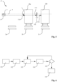
- the reflection microwave barrier 1 to Limit level monitoring in a work area 2 comprises a microwave transmitter 3 which continuously emits a time-modulated, namely frequency-modulated (FMCW) and/or amplitude-modulated and/or digitally coded, microwave signal 4 .
- the microwave transmitter 3 is designed as a microwave transceiver 6 in one component with a microwave receiver 5 , with the microwave receiver 5 receiving a reflection 7 of the microwave signal 4 .
- the microwave receiver 4 is arranged on the same side of the work area 2 to be monitored as the microwave transmitter 3.
- the microwave signal 4 is reflected at an origin 9 and thrown back to the microwave receiver 5 .
- a control unit 10 communicating with the microwave receiver 5 for detecting and monitoring echo signals 11a, 11b in the received reflection 7 of the microwave signal 4 is provided. If the control unit 10 determines that the amplitude of an echo signal 11a is occurring or increasing, it calculates its transit time and checks whether the origin 9 of the echo signal 11a is within the at least one working area 2 . Only in this case will the switching signal be output, which indicates that the fill level has been reached or exceeded.
- this embodiment manages without a static reflector 12—not shown here—since the filling material 8 itself has a reflective effect.
- control unit 10 stores static interference echoes in the form of static echo signals 11b for subsequent removal of the stored ones Interfering echoes from the reflected microwave signal 7.
- static echo signal 11b of the rear wall of the container containing filling material 8 can easily be ignored.
- the reflective microwave barrier 1 comprises the reflective microwave barrier 1, in addition to the features of the embodiment 1 , an immovable reflector 12 for reflecting the microwave signal 4 as a reflector echo 13.
- the control unit 10 is set up to emit the switching signal only if the amplitude of the reflector echo 13 falls and/or the transit time of the reflector echo occurs or rises in the amplitude of the echo signal 11a at the same time as the echo signal 11a, which is to be emitted indicating that the filling limit level has been reached, arises or rises 13 increases.
- the filling material 8 acts as a diagnostic in multiple, synergetically cooperating ways, namely on the one hand as a reflector of the echo signal 11a and on the other hand at the same time as a damper and delayer of the reflector echo 13.
- control unit 10 is also set up to output a warning signal if the amplitude of the reflector echo 13 falls below a predefined minimum reflector echo amplitude.
- the control unit 10 is also designed to automatically identify the reflector echo 13 when it is put into operation, for example by identifying a static echo signal with the highest intensity.
- the control unit can then, preferably automatically, define the working area 2 as the area between the microwave receiver 5 and the reflector 12 .
- the first working area 2a is defined by a first predefined minimum running time tmin1 and a first predefined maximum running time tmax1 assigned to it
- the second working area is defined by a second predefined minimum running time tmin1 and a second predefined maximum running time tmax1 assigned to it.
- the control unit can convert between a transit time and a location associated with this transit time along the direction of propagation, so that the definition of a transit time is equivalent to the definition of a spatial coordinate.
- the coordinates that correspond to the respective runtime are marked in the selected representation.
- the control unit When the amplitude of an echo signal 11a, 11b is detected or increases, the control unit first checks whether the transit time is greater than a predefined minimum transit time tmin1 or tmin2 and whether the transit time is less than a maximum transit time tmax1 or tmax2 assigned to this minimum transit time. The switching signal is only sent out in such a case. Thus, the echo signals 11c, 11d of the persons acting as foreign bodies 14a, 14b can easily be ignored.
- the minimum and maximum running times tmin1, tmin2, tmax1, tmax2 are entered via a user interface 15 and stored in the control unit 10 for simplified adaptation of the detection routines to the geometry specified by the containers of the filling goods.
- Figure 4a shows an exemplary embodiment of the invention in which a working area 2 is provided which corresponds to the interval between a minimum running time tmin1 and the maximum running time tmax1 associated with it.
- Figure 4b shows a corresponding intensity/time diagram, in which echo signals 11a, 11b that occur and a reflector echo 13 are drawn in schematically.
- the maximum propagation time tmax1 is predefined by a static reflector 12, which reflects the reflector echo 13.
- a foreign body 14a which throws back an echo signal 11a to the microwave receiver 5, is located in a region between a microwave receiver 5 and the minimum distance that is to be ignored and which corresponds to the minimum transit time tmin1. This signal will not lead to the output of a switching signal since its runtime is not longer than the minimum runtime tmin1.
- the echo signal 11a is reflected on a surface 16 in the area of the microwave receiver 5 and then thrown back again by the foreign body 14a to the microwave receiver 5 and recorded as a “ping pong” echo signal 11b.
- This "ping pong" echo signal 11b has a transit time that lies between the minimum transit time tmin1 and the maximum transit time tmax1, which corresponds to the echo signal of a - virtual, shown here dashed - foreign body (or a filling material above the limit fill level) in the working area 2, and would therefore in principle allow a switching signal to be output.
- the control unit 10 upon receipt of the first echo signal 11a with a propagation time below the at least one minimum propagation time tmin1 and a second echo signal 11b above the at least one minimum propagation time tmin1, the control unit 10 is set up to analyze whether the second echo signal 11b represents a reflection of the first echo signal 11a and only otherwise to output the switching signal.
- the reflection microwave barrier 1 is used in a signal box 17 for the detection of rail vehicles 18a, 18b.
- the microwave signal 4 is emitted by a microwave transmitter 3 and its reflection 7, which contains the echo signals 11a, 11b, 11c, is received by the microwave receiver 5.
- the work areas 2a, 2b, 2c are included predefined in such a way that the echo signal 11c of a foreign body 14a cannot be evaluated as an indicator for a rail vehicle arranged there.
- step 101 a time-modulated microwave signal is emitted continuously.
- step 102 a reflection of the microwave signal is received.
- echo signals (not shown in detail here—are detected and monitored in the received reflection of the microwave signal.
- step 104 when the amplitude of a detected or monitored echo signal arises or increases, its propagation time is calculated.
- step 105 the calculated transit time is used to determine whether the echo signal was reflected within at least one working area. For this purpose, the running time is compared, for example, with a minimum running time tmin1 or, for example, with a maximum running time tmax1.
- the switching signal is output in step 106 only if the origin of the echo signal is in the at least one working area; otherwise, according to step 103, the reflection of the microwave signal is monitored for the emergence or increase of echo signals.
- the reflection microwave barrier using highly integrated MMICs, which in a particularly advantageous embodiment can also contain elements for transmitting and/or receiving radar signals.
- a phase-locked loop (PLL) or a fractional-N-PLL can be used in particular to improve the linearity of an MMIC operating according to the FMCW principle.
- the microwave barrier have suitable energy management units, which can achieve an accumulation of energy by deactivating the microwave assembly over time.
- the wireless communication device may also be provided for setting the microwave barrier.
Landscapes
- Physics & Mathematics (AREA)
- Remote Sensing (AREA)
- Engineering & Computer Science (AREA)
- General Physics & Mathematics (AREA)
- Radar, Positioning & Navigation (AREA)
- Electromagnetism (AREA)
- Life Sciences & Earth Sciences (AREA)
- General Life Sciences & Earth Sciences (AREA)
- Geophysics (AREA)
- Computer Networks & Wireless Communication (AREA)
- Fluid Mechanics (AREA)
- Thermal Sciences (AREA)
- Environmental & Geological Engineering (AREA)
- Geology (AREA)
- Business, Economics & Management (AREA)
- Emergency Management (AREA)
- Radar Systems Or Details Thereof (AREA)
Claims (15)
- Barrière hyperfréquence de réflexion (1) pour la surveillance d'un niveau limite dans au moins une zone de travail (2) en générant un signal de commutation, comprenant :un émetteur hyperfréquence (3) pour émettre en continu un signal hyperfréquence (4) modulé dans le temps,un récepteur hyperfréquence (5), qui est agencé du même côté de la au moins une zone de travail (2) le long d'une direction de propagation du signal hyperfréquence que l'émetteur hyperfréquence (3), et destiné à recevoir une réflexion (7) du signal hyperfréquence (4),une unité de commande (10) qui communique avec le récepteur hyperfréquence (5) pour détecter et surveiller des signaux d'écho (11a-11c) dans la réflexion (7) reçue du signal hyperfréquence (4),dans laquelle l'unité de commande (10) est configurée pour calculer le temps de propagation d'un signal d'écho (11a) lors de l'apparition ou de l'augmentation de l'amplitude du signal d'écho de la réflexion et déterminer, au moyen du temps de propagation calculé, si l'origine (9) du signal d'écho (11a) se situe dans la au moins une zone de travail (2),et délivrer le signal de commutation uniquement dans le cas où l'origine du signal d'écho de la réflexion se situe dans la au moins une zone de travail,caractérisée en ce que l'unité de commande est en outre configurée pourdans le cas où l'origine (9) du signal d'écho le long de la direction de propagation du signal hyperfréquence ne se situe pas dans la au moins une zone de travail, ignorer le signal d'écho de la réflexion d'un corps étranger lors d'une détection d'un niveau de remplissage.
- Barrière hyperfréquence de réflexion (1) selon la revendication 1,
dans laquelle l'unité de commande (10) est configurée pour déterminer si l'origine (9) du signal d'écho (11a) se situe dans la au moins une zone de travail (2), en vérifiant si le temps de propagation est supérieur à au moins un temps de propagation minimal (tmin1) prédéfini. - Barrière hyperfréquence de réflexion (1) selon l'une des revendications précédentes,
dans laquelle l'unité de commande (10) est configurée pour déterminer si l'origine du signal d'écho (11a) se situe dans la au moins une zone de travail (2), en vérifiant si le temps de propagation est inférieur à au moins un temps de propagation maximal (tmax1) prédéfini. - Barrière hyperfréquence de réflexion (1) selon les revendications 2 et (3),
dans laquelle sont prévues au moins deux zones de travail (2a, 2b) séparées le long d'une direction de propagation du signal hyperfréquence (4). - Barrière hyperfréquence de réflexion (1) selon l'une des revendications précédentes, comprenant une interface utilisateur (15) pour définir la au moins une zone de travail (2).
- Barrière hyperfréquence de réflexion (1) selon l'une des revendications précédentes, comprenant un réflecteur immobile (12) pour la réflexion du signal hyperfréquence (4) sous forme d'écho de réflecteur (13),
dans laquelle l'unité de commande (10) est configurée pour générer le signal de commutation uniquement si, pendant l'apparition ou l'augmentation de l'amplitude du signal d'écho (11a), l'amplitude de l'écho de réflecteur (13) diminue et/ou le temps de propagation de l'écho de réflecteur (13) augmente simultanément. - Barrière hyperfréquence de réflexion (1) selon la revendication 6, dans laquelle l'unité de commande (10) est configurée pour identifier l'écho de réflecteur (12) pendant la mise en service et définir la zone de travail (2) comme étant une zone entre le récepteur hyperfréquence (5) et le réflecteur (12).
- Barrière hyperfréquence de réflexion (1) selon l'une des revendications 6 ou 7,
dans laquelle l'unité de commande (10) est configurée pour générer un signal d'avertissement lorsque l'amplitude de l'écho de réflecteur (11a) diminue en dessous d'une amplitude d'écho de réflecteur minimale prédéfinie. - Barrière hyperfréquence de réflexion (1) selon la revendication 2,
dans laquelle l'unité de commande (10) est configurée pour analyser, lors de la réception d'un premier signal d'écho (11a) ayant un temps de propagation inférieur au au moins un temps de propagation minimal (tmin1) et d'un second signal d'écho (11b) ayant un temps de propagation supérieur au au moins un temps de propagation minimal (tmin1), si le second signal d'écho (11b) représente une réflexion du premier signal d'écho (11a), et sinon générer uniquement le signal de commutation. - Barrière hyperfréquence de réflexion (1) selon la revendication 9,
dans laquelle la caractéristique d'émission de l'émetteur hyperfréquence (3) peut être commutée entre au moins deux profils et dans laquelle l'unité de commande (10) est configurée pour analyser si le second signal d'écho (11b) représente une réflexion du premier signal d'écho (11a), en commutant la caractéristique d'émission de la barrière hyperfréquence de réflexion (1) entre au moins deux profils et en vérifiant si, pendant ce temps, il existe une corrélation entre le premier signal d'écho (11a) et le second signal d'écho (11b). - Barrière hyperfréquence de réflexion (1) selon l'une des revendications précédentes, dans laquelle l'unité de commande (10) est configurée pour enregistrer des échos parasites statiques pendant la mise en service, afin de tenir compte des échos parasites enregistrés pendant une phase de fonctionnement ultérieure lors de l'évaluation d'une réflexion (7) d'un signal hyperfréquence (4).
- Procédé pour surveiller un niveau limite dans au moins une zone de travail (2) en générant un signal de commutation au moyen d'une barrière hyperfréquence de réflexion (1), dans lequel un signal hyperfréquence (4) modulé dans le temps est émis en continu, et une réflexion (7) du signal hyperfréquence (4) est reçue, et des signaux d'écho (11a, 11b) dans la réflexion (7) reçue du signal hyperfréquence (4) sont détectés et surveillés, dans lequel le temps de propagation d'un signal d'écho (11a) lors de l'apparition ou de l'augmentation de l'amplitude du signal d'écho de la réflexion est calculé, et au moyen du temps de propagation calculé, il est déterminé si le signal d'écho (11a) a été réfléchi dans la au moins une zone de travail (2) et uniquement dans le cas où l'origine du signal d'écho de la réflexion se situe dans la au moins une zone de travail, le signal de commutation est généré,
caractérisé en ce que
dans le cas où l'origine (9) du signal d'écho le long de la direction de propagation du signal hyperfréquence ne se situe pas dans la au moins une zone de travail, le signal d'écho de la réflexion d'un corps étranger est ignoré lors de la détection d'un niveau de remplissage. - Programme informatique comportant des instructions qui amènent le dispositif de la revendication 1 à exécuter les étapes de procédé selon la revendication 12.
- Support lisible par ordinateur sur lequel est mémorisé le programme informatique selon la revendication 13.
- Utilisation d'une barrière hyperfréquence de réflexion (1) selon l'une des revendications 1 à 11 dans un poste de commande (17) pour la détection d'un véhicule ferroviaire (18a ; 18b) dans au moins une zone de travail (2).
Priority Applications (4)
| Application Number | Priority Date | Filing Date | Title |
|---|---|---|---|
| EP16174419.8A EP3258296B1 (fr) | 2016-06-14 | 2016-06-14 | Barriere de micro-ondes de reflexion |
| DK16174419.8T DK3258296T3 (da) | 2016-06-14 | 2016-06-14 | Reflektionsmikrobølgeskranke |
| CN201710433513.5A CN107505027B (zh) | 2016-06-14 | 2017-06-09 | 反射微波屏障 |
| US15/622,399 US10704948B2 (en) | 2016-06-14 | 2017-06-14 | Reflection microwave barrier |
Applications Claiming Priority (1)
| Application Number | Priority Date | Filing Date | Title |
|---|---|---|---|
| EP16174419.8A EP3258296B1 (fr) | 2016-06-14 | 2016-06-14 | Barriere de micro-ondes de reflexion |
Publications (2)
| Publication Number | Publication Date |
|---|---|
| EP3258296A1 EP3258296A1 (fr) | 2017-12-20 |
| EP3258296B1 true EP3258296B1 (fr) | 2023-07-26 |
Family
ID=56132810
Family Applications (1)
| Application Number | Title | Priority Date | Filing Date |
|---|---|---|---|
| EP16174419.8A Active EP3258296B1 (fr) | 2016-06-14 | 2016-06-14 | Barriere de micro-ondes de reflexion |
Country Status (4)
| Country | Link |
|---|---|
| US (1) | US10704948B2 (fr) |
| EP (1) | EP3258296B1 (fr) |
| CN (1) | CN107505027B (fr) |
| DK (1) | DK3258296T3 (fr) |
Families Citing this family (6)
| Publication number | Priority date | Publication date | Assignee | Title |
|---|---|---|---|---|
| FR3093210B1 (fr) * | 2019-02-27 | 2021-02-19 | Greenerwave | Système de détection de récepteurs |
| DE102019204881A1 (de) | 2019-04-05 | 2020-10-08 | Vega Grieshaber Kg | Radarmessgerät mit integrierter Sicherheitsbereichsüberwachung |
| EP3719533B1 (fr) | 2019-04-05 | 2022-05-25 | VEGA Grieshaber KG | Barrière à micro-ondes réfléchissante multidimensionnelle |
| DE102019209768A1 (de) * | 2019-07-03 | 2021-01-07 | Audi Ag | Brennstoffzellenvorrichtung sowie Kraftfahrzeug |
| JP7535876B2 (ja) | 2020-06-10 | 2024-08-19 | シャープ株式会社 | 収容物検出装置及び収容物検出方法 |
| EP4290280A1 (fr) * | 2022-06-10 | 2023-12-13 | VEGA Grieshaber KG | Système de confinement de micro-ondes |
Citations (1)
| Publication number | Priority date | Publication date | Assignee | Title |
|---|---|---|---|---|
| WO2002027349A2 (fr) * | 2000-09-27 | 2002-04-04 | Endress + Hauser Gmbh + Co. Kg | Procede de detection de l'etat limite d'une matiere et dispositif associe |
Family Cites Families (14)
| Publication number | Priority date | Publication date | Assignee | Title |
|---|---|---|---|---|
| DE3302731A1 (de) | 1983-01-27 | 1984-08-02 | VEGA Grieshaber GmbH & Co, 7620 Wolfach | Mikrowellenschranke |
| DE19723978C2 (de) * | 1997-06-06 | 1999-03-25 | Endress Hauser Gmbh Co | Verfahren zur Messung des Füllstands eines Füllguts in einem Behälter nach dem Radarprinzip |
| EP1128169A1 (fr) | 1999-12-29 | 2001-08-29 | Endress + Hauser GmbH + Co. | Méthode et dispositif pour la détermination du niveau limite d'un produit dans un récipient |
| DE10325267A1 (de) * | 2003-06-03 | 2004-12-23 | Endress + Hauser Gmbh + Co. Kg | Anordnung und Verfahren zur Füllstandsmessung |
| BRPI0418141A2 (pt) * | 2003-12-23 | 2017-03-01 | Inesa East Ltd | um método para a avaliação não evasiva do nível do material de enchimento de um recipiente |
| US7333900B2 (en) * | 2004-08-16 | 2008-02-19 | Vega Grieshaber Kg | Automatic parasitic echo storage |
| SE0403165D0 (sv) * | 2004-12-23 | 2004-12-23 | Saab Rosemount Tank Radar Ab | A radar level gauge system |
| DE202005015353U1 (de) * | 2005-09-28 | 2006-01-19 | Uas Messtechnik Gmbh | Anordnung zur Messung eines Schmelzspiegelniveaus |
| US8830118B2 (en) * | 2010-09-07 | 2014-09-09 | Rosemount Tank Radar Ab | Radar level gauge system with operation monitoring functionality |
| CN102607670B (zh) * | 2012-04-01 | 2014-07-02 | 郑贵林 | 一种气介式自标定超声波液位测量方法及其液位计 |
| US9518859B2 (en) * | 2013-01-29 | 2016-12-13 | Apm Automation Solutions Ltd | System and method for content estimate based detection of obstacles within a bin |
| DE102013103972B4 (de) | 2013-04-19 | 2017-04-06 | Sick Ag | Objektlokalisierung auf einer Fördereinrichtung |
| DE202014104956U1 (de) | 2014-10-17 | 2016-01-19 | Sick Ag | Radarreflexionsschranke zur Erfassung von Objekten |
| CN104913830A (zh) * | 2015-05-15 | 2015-09-16 | 中国科学院沈阳自动化研究所 | 一种基于曲线拟合的雷达物位计信号处理方法 |
-
2016
- 2016-06-14 EP EP16174419.8A patent/EP3258296B1/fr active Active
- 2016-06-14 DK DK16174419.8T patent/DK3258296T3/da active
-
2017
- 2017-06-09 CN CN201710433513.5A patent/CN107505027B/zh active Active
- 2017-06-14 US US15/622,399 patent/US10704948B2/en active Active
Patent Citations (1)
| Publication number | Priority date | Publication date | Assignee | Title |
|---|---|---|---|---|
| WO2002027349A2 (fr) * | 2000-09-27 | 2002-04-04 | Endress + Hauser Gmbh + Co. Kg | Procede de detection de l'etat limite d'une matiere et dispositif associe |
Also Published As
| Publication number | Publication date |
|---|---|
| US10704948B2 (en) | 2020-07-07 |
| US20170356787A1 (en) | 2017-12-14 |
| CN107505027B (zh) | 2021-05-14 |
| EP3258296A1 (fr) | 2017-12-20 |
| CN107505027A (zh) | 2017-12-22 |
| DK3258296T3 (da) | 2023-09-04 |
Similar Documents
| Publication | Publication Date | Title |
|---|---|---|
| EP3258296B1 (fr) | Barriere de micro-ondes de reflexion | |
| EP2469296B1 (fr) | Capteur optoélectronique et procédé destiné à la détection et la détermination de l'éloignement d'objets | |
| DE102009001010B4 (de) | Verfahren zur Ermittlung und Überwachung des Füllstands eines Mediums in einem Behälter nach einem Laufzeitmessverfahren | |
| EP1342101A1 (fr) | Procede radar a impulsions, detecteur radar a impulsions et systeme correspondant | |
| EP3435117B1 (fr) | Capteur et procédé de détection et de détermination des distances entre des objets | |
| EP3025128B1 (fr) | Procédé pour déterminer et surveiller le niveau d'un fluide dans un récipient selon un procédé de mesure du temps de propagation | |
| EP3232224B1 (fr) | Capteur telemetrique optoelectronique et procede de detection et de determination de distances entre des objets | |
| EP2104839A1 (fr) | Procédé pour déterminer et surveiller le niveau d'un fluide dans un récipient selon un procédé de mesure du temps de propagation | |
| DE4308373A1 (de) | Verfahren zur Erkennung und Separation von Nutz- und Störechos im Empfangssignal von Abstandssensoren, welche nach dem Impuls-Echo-Prinzip arbeiten | |
| EP3287809B1 (fr) | Procédé de fonctionnement d'un dispositif de baleyage et dispositif de baleyage | |
| DE102010024328B4 (de) | Radarvorrichtung mit situationsadaptiver Modulationsumschaltung und Steuerungsverfahren | |
| EP3220164B1 (fr) | Procédé de fonctionnement d'un capteur écartométrique de surveillance et capteur écartométrique de surveillance | |
| DE3932665A1 (de) | Ueberwachungsvorrichtung | |
| EP3746753B1 (fr) | Procédé de détection d'états d'erreur potentiels sur un dispositif de mesure de remplissage à base de fmcw | |
| EP1522879B1 (fr) | Capteur opto-électronique et procédé de detection d'un objet dans une zone de survéillance | |
| EP2739945B1 (fr) | Appareil de mesure du niveau de remplissage et procédé de détermination d'un rapport fonctionnel entre différentes pistes | |
| DE102017111367A1 (de) | Abstandsmesssystem, -verfahren und diese verwendendes Robotersystem | |
| EP2977786B1 (fr) | Capteur telemetrique destine a la detection et la determination de l'eloignement d'objets | |
| DE102022130166A1 (de) | Sicherheitssystem und Verfahren mit einem Sicherheitssystem | |
| EP1283412A2 (fr) | Procédé et dispositif de détection d'une opération de remplissage | |
| DE102010064682B3 (de) | Optoelektronischer Sensor und Verfahren zur Erfassung und Abstandsbestimmung von Objekten | |
| EP4524608B1 (fr) | Capteur pour surveiller une zone | |
| EP2718917B1 (fr) | Détecteur de fumées et son procédé de fonctionnement | |
| DE202022106398U1 (de) | Sicherheitssystem mit einem Sicherheitssystem | |
| DE19954156A1 (de) | Lichtschranke |
Legal Events
| Date | Code | Title | Description |
|---|---|---|---|
| PUAI | Public reference made under article 153(3) epc to a published international application that has entered the european phase |
Free format text: ORIGINAL CODE: 0009012 |
|
| STAA | Information on the status of an ep patent application or granted ep patent |
Free format text: STATUS: REQUEST FOR EXAMINATION WAS MADE |
|
| 17P | Request for examination filed |
Effective date: 20170503 |
|
| AK | Designated contracting states |
Kind code of ref document: A1 Designated state(s): AL AT BE BG CH CY CZ DE DK EE ES FI FR GB GR HR HU IE IS IT LI LT LU LV MC MK MT NL NO PL PT RO RS SE SI SK SM TR |
|
| AX | Request for extension of the european patent |
Extension state: BA ME |
|
| STAA | Information on the status of an ep patent application or granted ep patent |
Free format text: STATUS: EXAMINATION IS IN PROGRESS |
|
| 17Q | First examination report despatched |
Effective date: 20200803 |
|
| GRAP | Despatch of communication of intention to grant a patent |
Free format text: ORIGINAL CODE: EPIDOSNIGR1 |
|
| STAA | Information on the status of an ep patent application or granted ep patent |
Free format text: STATUS: GRANT OF PATENT IS INTENDED |
|
| RIC1 | Information provided on ipc code assigned before grant |
Ipc: G01S 13/88 20060101ALI20230202BHEP Ipc: G01S 13/34 20060101ALI20230202BHEP Ipc: G01F 23/284 20060101ALI20230202BHEP Ipc: G01V 8/00 20060101ALI20230202BHEP Ipc: G01V 3/12 20060101AFI20230202BHEP |
|
| INTG | Intention to grant announced |
Effective date: 20230220 |
|
| GRAS | Grant fee paid |
Free format text: ORIGINAL CODE: EPIDOSNIGR3 |
|
| GRAA | (expected) grant |
Free format text: ORIGINAL CODE: 0009210 |
|
| STAA | Information on the status of an ep patent application or granted ep patent |
Free format text: STATUS: THE PATENT HAS BEEN GRANTED |
|
| P01 | Opt-out of the competence of the unified patent court (upc) registered |
Effective date: 20230524 |
|
| AK | Designated contracting states |
Kind code of ref document: B1 Designated state(s): AL AT BE BG CH CY CZ DE DK EE ES FI FR GB GR HR HU IE IS IT LI LT LU LV MC MK MT NL NO PL PT RO RS SE SI SK SM TR |
|
| RAP3 | Party data changed (applicant data changed or rights of an application transferred) |
Owner name: VEGA GRIESHABER KG |
|
| REG | Reference to a national code |
Ref country code: GB Ref legal event code: FG4D Free format text: NOT ENGLISH |
|
| REG | Reference to a national code |
Ref country code: CH Ref legal event code: EP |
|
| REG | Reference to a national code |
Ref country code: DE Ref legal event code: R096 Ref document number: 502016015960 Country of ref document: DE |
|
| REG | Reference to a national code |
Ref country code: IE Ref legal event code: FG4D Free format text: LANGUAGE OF EP DOCUMENT: GERMAN |
|
| REG | Reference to a national code |
Ref country code: DK Ref legal event code: T3 Effective date: 20230830 |
|
| REG | Reference to a national code |
Ref country code: LT Ref legal event code: MG9D |
|
| REG | Reference to a national code |
Ref country code: NL Ref legal event code: MP Effective date: 20230726 |
|
| PG25 | Lapsed in a contracting state [announced via postgrant information from national office to epo] |
Ref country code: NL Free format text: LAPSE BECAUSE OF FAILURE TO SUBMIT A TRANSLATION OF THE DESCRIPTION OR TO PAY THE FEE WITHIN THE PRESCRIBED TIME-LIMIT Effective date: 20230726 |
|
| PG25 | Lapsed in a contracting state [announced via postgrant information from national office to epo] |
Ref country code: GR Free format text: LAPSE BECAUSE OF FAILURE TO SUBMIT A TRANSLATION OF THE DESCRIPTION OR TO PAY THE FEE WITHIN THE PRESCRIBED TIME-LIMIT Effective date: 20231027 |
|
| PG25 | Lapsed in a contracting state [announced via postgrant information from national office to epo] |
Ref country code: IS Free format text: LAPSE BECAUSE OF FAILURE TO SUBMIT A TRANSLATION OF THE DESCRIPTION OR TO PAY THE FEE WITHIN THE PRESCRIBED TIME-LIMIT Effective date: 20231126 |
|
| PG25 | Lapsed in a contracting state [announced via postgrant information from national office to epo] |
Ref country code: SE Free format text: LAPSE BECAUSE OF FAILURE TO SUBMIT A TRANSLATION OF THE DESCRIPTION OR TO PAY THE FEE WITHIN THE PRESCRIBED TIME-LIMIT Effective date: 20230726 Ref country code: RS Free format text: LAPSE BECAUSE OF FAILURE TO SUBMIT A TRANSLATION OF THE DESCRIPTION OR TO PAY THE FEE WITHIN THE PRESCRIBED TIME-LIMIT Effective date: 20230726 Ref country code: PT Free format text: LAPSE BECAUSE OF FAILURE TO SUBMIT A TRANSLATION OF THE DESCRIPTION OR TO PAY THE FEE WITHIN THE PRESCRIBED TIME-LIMIT Effective date: 20231127 Ref country code: NO Free format text: LAPSE BECAUSE OF FAILURE TO SUBMIT A TRANSLATION OF THE DESCRIPTION OR TO PAY THE FEE WITHIN THE PRESCRIBED TIME-LIMIT Effective date: 20231026 Ref country code: LV Free format text: LAPSE BECAUSE OF FAILURE TO SUBMIT A TRANSLATION OF THE DESCRIPTION OR TO PAY THE FEE WITHIN THE PRESCRIBED TIME-LIMIT Effective date: 20230726 Ref country code: LT Free format text: LAPSE BECAUSE OF FAILURE TO SUBMIT A TRANSLATION OF THE DESCRIPTION OR TO PAY THE FEE WITHIN THE PRESCRIBED TIME-LIMIT Effective date: 20230726 Ref country code: IS Free format text: LAPSE BECAUSE OF FAILURE TO SUBMIT A TRANSLATION OF THE DESCRIPTION OR TO PAY THE FEE WITHIN THE PRESCRIBED TIME-LIMIT Effective date: 20231126 Ref country code: HR Free format text: LAPSE BECAUSE OF FAILURE TO SUBMIT A TRANSLATION OF THE DESCRIPTION OR TO PAY THE FEE WITHIN THE PRESCRIBED TIME-LIMIT Effective date: 20230726 Ref country code: GR Free format text: LAPSE BECAUSE OF FAILURE TO SUBMIT A TRANSLATION OF THE DESCRIPTION OR TO PAY THE FEE WITHIN THE PRESCRIBED TIME-LIMIT Effective date: 20231027 Ref country code: FI Free format text: LAPSE BECAUSE OF FAILURE TO SUBMIT A TRANSLATION OF THE DESCRIPTION OR TO PAY THE FEE WITHIN THE PRESCRIBED TIME-LIMIT Effective date: 20230726 |
|
| PG25 | Lapsed in a contracting state [announced via postgrant information from national office to epo] |
Ref country code: PL Free format text: LAPSE BECAUSE OF FAILURE TO SUBMIT A TRANSLATION OF THE DESCRIPTION OR TO PAY THE FEE WITHIN THE PRESCRIBED TIME-LIMIT Effective date: 20230726 |
|
| PG25 | Lapsed in a contracting state [announced via postgrant information from national office to epo] |
Ref country code: ES Free format text: LAPSE BECAUSE OF FAILURE TO SUBMIT A TRANSLATION OF THE DESCRIPTION OR TO PAY THE FEE WITHIN THE PRESCRIBED TIME-LIMIT Effective date: 20230726 |
|
| REG | Reference to a national code |
Ref country code: DE Ref legal event code: R097 Ref document number: 502016015960 Country of ref document: DE |
|
| PG25 | Lapsed in a contracting state [announced via postgrant information from national office to epo] |
Ref country code: SM Free format text: LAPSE BECAUSE OF FAILURE TO SUBMIT A TRANSLATION OF THE DESCRIPTION OR TO PAY THE FEE WITHIN THE PRESCRIBED TIME-LIMIT Effective date: 20230726 Ref country code: RO Free format text: LAPSE BECAUSE OF FAILURE TO SUBMIT A TRANSLATION OF THE DESCRIPTION OR TO PAY THE FEE WITHIN THE PRESCRIBED TIME-LIMIT Effective date: 20230726 Ref country code: ES Free format text: LAPSE BECAUSE OF FAILURE TO SUBMIT A TRANSLATION OF THE DESCRIPTION OR TO PAY THE FEE WITHIN THE PRESCRIBED TIME-LIMIT Effective date: 20230726 Ref country code: EE Free format text: LAPSE BECAUSE OF FAILURE TO SUBMIT A TRANSLATION OF THE DESCRIPTION OR TO PAY THE FEE WITHIN THE PRESCRIBED TIME-LIMIT Effective date: 20230726 Ref country code: CZ Free format text: LAPSE BECAUSE OF FAILURE TO SUBMIT A TRANSLATION OF THE DESCRIPTION OR TO PAY THE FEE WITHIN THE PRESCRIBED TIME-LIMIT Effective date: 20230726 Ref country code: SK Free format text: LAPSE BECAUSE OF FAILURE TO SUBMIT A TRANSLATION OF THE DESCRIPTION OR TO PAY THE FEE WITHIN THE PRESCRIBED TIME-LIMIT Effective date: 20230726 |
|
| PLBE | No opposition filed within time limit |
Free format text: ORIGINAL CODE: 0009261 |
|
| STAA | Information on the status of an ep patent application or granted ep patent |
Free format text: STATUS: NO OPPOSITION FILED WITHIN TIME LIMIT |
|
| 26N | No opposition filed |
Effective date: 20240429 |
|
| PG25 | Lapsed in a contracting state [announced via postgrant information from national office to epo] |
Ref country code: SI Free format text: LAPSE BECAUSE OF FAILURE TO SUBMIT A TRANSLATION OF THE DESCRIPTION OR TO PAY THE FEE WITHIN THE PRESCRIBED TIME-LIMIT Effective date: 20230726 |
|
| PG25 | Lapsed in a contracting state [announced via postgrant information from national office to epo] |
Ref country code: BG Free format text: LAPSE BECAUSE OF FAILURE TO SUBMIT A TRANSLATION OF THE DESCRIPTION OR TO PAY THE FEE WITHIN THE PRESCRIBED TIME-LIMIT Effective date: 20230726 |
|
| PG25 | Lapsed in a contracting state [announced via postgrant information from national office to epo] |
Ref country code: BG Free format text: LAPSE BECAUSE OF FAILURE TO SUBMIT A TRANSLATION OF THE DESCRIPTION OR TO PAY THE FEE WITHIN THE PRESCRIBED TIME-LIMIT Effective date: 20230726 |
|
| PG25 | Lapsed in a contracting state [announced via postgrant information from national office to epo] |
Ref country code: MC Free format text: LAPSE BECAUSE OF FAILURE TO SUBMIT A TRANSLATION OF THE DESCRIPTION OR TO PAY THE FEE WITHIN THE PRESCRIBED TIME-LIMIT Effective date: 20230726 |
|
| PG25 | Lapsed in a contracting state [announced via postgrant information from national office to epo] |
Ref country code: LU Free format text: LAPSE BECAUSE OF NON-PAYMENT OF DUE FEES Effective date: 20240614 |
|
| PG25 | Lapsed in a contracting state [announced via postgrant information from national office to epo] |
Ref country code: IE Free format text: LAPSE BECAUSE OF NON-PAYMENT OF DUE FEES Effective date: 20240614 |
|
| PG25 | Lapsed in a contracting state [announced via postgrant information from national office to epo] |
Ref country code: BE Free format text: LAPSE BECAUSE OF NON-PAYMENT OF DUE FEES Effective date: 20240630 |
|
| REG | Reference to a national code |
Ref country code: BE Ref legal event code: MM Effective date: 20240630 |
|
| PGFP | Annual fee paid to national office [announced via postgrant information from national office to epo] |
Ref country code: DE Payment date: 20250618 Year of fee payment: 10 |
|
| PGFP | Annual fee paid to national office [announced via postgrant information from national office to epo] |
Ref country code: GB Payment date: 20250620 Year of fee payment: 10 Ref country code: DK Payment date: 20250618 Year of fee payment: 10 |
|
| PGFP | Annual fee paid to national office [announced via postgrant information from national office to epo] |
Ref country code: FR Payment date: 20250626 Year of fee payment: 10 |
|
| REG | Reference to a national code |
Ref country code: AT Ref legal event code: MM01 Ref document number: 1592574 Country of ref document: AT Kind code of ref document: T Effective date: 20240614 |
|
| PGFP | Annual fee paid to national office [announced via postgrant information from national office to epo] |
Ref country code: IT Payment date: 20250630 Year of fee payment: 10 |
|
| PG25 | Lapsed in a contracting state [announced via postgrant information from national office to epo] |
Ref country code: AT Free format text: LAPSE BECAUSE OF NON-PAYMENT OF DUE FEES Effective date: 20240614 |
|
| PGFP | Annual fee paid to national office [announced via postgrant information from national office to epo] |
Ref country code: CH Payment date: 20250701 Year of fee payment: 10 |
|
| PG25 | Lapsed in a contracting state [announced via postgrant information from national office to epo] |
Ref country code: CY Free format text: LAPSE BECAUSE OF FAILURE TO SUBMIT A TRANSLATION OF THE DESCRIPTION OR TO PAY THE FEE WITHIN THE PRESCRIBED TIME-LIMIT; INVALID AB INITIO Effective date: 20160614 |
|
| PG25 | Lapsed in a contracting state [announced via postgrant information from national office to epo] |
Ref country code: HU Free format text: LAPSE BECAUSE OF FAILURE TO SUBMIT A TRANSLATION OF THE DESCRIPTION OR TO PAY THE FEE WITHIN THE PRESCRIBED TIME-LIMIT; INVALID AB INITIO Effective date: 20160614 |