EP4290280A1 - Système de confinement de micro-ondes - Google Patents
Système de confinement de micro-ondes Download PDFInfo
- Publication number
- EP4290280A1 EP4290280A1 EP23178107.1A EP23178107A EP4290280A1 EP 4290280 A1 EP4290280 A1 EP 4290280A1 EP 23178107 A EP23178107 A EP 23178107A EP 4290280 A1 EP4290280 A1 EP 4290280A1
- Authority
- EP
- European Patent Office
- Prior art keywords
- microwave
- barrier
- barriers
- receiving unit
- unit
- Prior art date
- Legal status (The legal status is an assumption and is not a legal conclusion. Google has not performed a legal analysis and makes no representation as to the accuracy of the status listed.)
- Pending
Links
Images


Classifications
-
- G—PHYSICS
- G01—MEASURING; TESTING
- G01V—GEOPHYSICS; GRAVITATIONAL MEASUREMENTS; DETECTING MASSES OR OBJECTS; TAGS
- G01V8/00—Prospecting or detecting by optical means
- G01V8/10—Detecting, e.g. by using light barriers
- G01V8/20—Detecting, e.g. by using light barriers using multiple transmitters or receivers
-
- G—PHYSICS
- G01—MEASURING; TESTING
- G01V—GEOPHYSICS; GRAVITATIONAL MEASUREMENTS; DETECTING MASSES OR OBJECTS; TAGS
- G01V3/00—Electric or magnetic prospecting or detecting; Measuring magnetic field characteristics of the earth, e.g. declination, deviation
- G01V3/12—Electric or magnetic prospecting or detecting; Measuring magnetic field characteristics of the earth, e.g. declination, deviation operating with electromagnetic waves
-
- G—PHYSICS
- G01—MEASURING; TESTING
- G01V—GEOPHYSICS; GRAVITATIONAL MEASUREMENTS; DETECTING MASSES OR OBJECTS; TAGS
- G01V8/00—Prospecting or detecting by optical means
- G01V8/005—Prospecting or detecting by optical means operating with millimetre waves, e.g. measuring the black losey radiation
Definitions
- a microwave barrier typically emits a continuous wave microwave signal towards an associated receiver. If the direct transmission path from transmitter to receiver is interrupted by an object or by a fill level in a container, this is noticeable by a missing or reduced reception level in the receiver. The drop in the reception level can be detected in a receiver and converted into a switching signal.
- a system with two receivers and a transmitter or two microwave barriers that work completely independently of each other can be used. If an object passes the barriers set up in this way, a direction of passage can be determined from the switching sequence.
- microwave radiation from a microwave transmitter unit of a microwave barrier can interfere with a reception unit of an adjacent further microwave barrier.
- This can affect the sensitivity and thus also the signal-to-noise ratio of the individual receiving unit to reduce.
- Such a reduced signal-to-noise ratio can result in an increase in the probability of malfunctions or incorrect switching of the affected microwave barrier.
- different polarization levels can typically be selected for the neighboring microwave barriers.
- the positions of the transmitter and receiver of adjacent microwave barriers can typically be swapped so that a transmitter of one microwave barrier is arranged adjacent to a receiver of the other microwave barrier. This means that the transmitter of one microwave barrier cannot directly interfere with the receiver of the other microwave barrier. This allows the two microwave barriers to be decoupled.
- the signal-to-noise ratio can no longer be improved with the measures described above.
- Decoupling the microwave barriers using different polarization levels of the microwave radiation is also less effective the more microwave barriers are operated in close proximity to one another. This means that the interference caused by microwave transmitting units in receiving units that are not associated with the microwave barrier, i.e. external receiving units, can have an increased effect with the number of microwave barriers. For example, in order to determine the position of an object in a room or a filling level in a container, more than two microwave barriers at a short spatial distance from one another may be necessary.
- a microwave barrier system with a first microwave barrier and at least one second microwave barrier is proposed.
- a microwave transmitter unit of the first microwave barrier has an electrically tunable microwave generator, wherein the first microwave barrier is set up based on the microwave transmitter unit to be operated with a first selectable microwave frequency.
- a microwave transmitter unit of the second microwave barrier has an electrically tunable microwave generator, and the first microwave barrier is, based on the microwave transmitter unit, set up to be operated with a second selectable microwave frequency.
- the first microwave barrier and the second microwave barrier each have a microwave transmitting unit and a microwave receiving unit.
- the microwave barrier system is set up by means of the respective microwave receiving unit to determine microwave operating channels, in particular for the operational operation of the respective microwave barrier, in an available frequency range for microwave barriers and the microwave barrier system is set up to correspond to the respective microwave barriers of the microwave barrier.
- the respective microwave barrier has a communication unit which is set up to signally couple the respective microwave receiving unit to the respective microwave transmitting unit, wired and/or wirelessly, in order to use the microwave operating channel for the operation of the respective microwave barrier from the microwave Receiving unit to transmit to the microwave transmitter unit.
- the respective microwave receiving unit can be coupled to the respective microwave transmitting unit of the respective microwave barrier by means of a microwave signal based on the respective microwave operating channel in order to establish a coupling path between the respective microwave transmitting unit and the respective receiving unit .
- the microwave barrier system can be set up to determine attenuation of the microwave signal in the respective coupling path.
- the available frequency range can be stored in the microwave barrier system, in particular by means of the respective microwave reception unit, and/or can be made available for operation of the microwave barrier system, in particular the respective microwave reception unit.
- the microwave receiving unit can be set up to determine the microwave operating channel from the available frequency range for microwave barriers in order to reduce mutual interference between the microwave barriers.
- the communication unit of the respective microwave barrier can couple the microwave receiving unit with the respective microwave transmitter unit monodirectionally and/or bidirectionally in order to transmit the microwave operating channel from the microwave receiving unit to the microwave transmitter unit.
- This coupling can be independent of the coupling of the microwave transmitter unit with the microwave receiver unit, based on the selectable microwave frequency, by means of which attenuation in the coupling path of the respective microwave barrier can be determined.
- Such a signal-related coupling by means of the communication unit can take place, for example, by means of a supply line of the microwave receiving unit and/or the microwave transmitting unit and/or a separate wired coupling and/or by means of a wireless signal-related coupling, such as a radio connection, for example via Bluetooth or WLAN .
- the respective communication unit can have at least two communication sub-units, the microwave receiving unit having one communication sub-unit and the microwave transmitting unit having the second communication sub-unit, each of which is responsible for the transmission of the specific microwave operating channel from the microwave receiving unit to the microwave transmitter unit and/or for a reverse Transmission from the microwave transmitter unit to the microwave receiver unit is set up.
- the microwave transmitter unit of the respective microwave barrier can be set up to generate a microwave signal and to radiate it in the direction of the microwave receiver unit, the microwave receiver unit being arranged spatially away from the microwave transmitter unit, and the respective microwave transmitter unit of the respective Microwave receiving unit of a respective microwave barrier are assigned to each other.
- a coupling path can be defined between the microwave transmitting unit and the associated receiving unit, which characterizes the spatial area, in that the microwave transmitting unit and the receiving unit use a respective microwave signal, corresponding to the respective microwave frequency of the corresponding microwave operating unit. Channel, are coupled. If the direct transmission path from the microwave transmitter unit to the microwave receiver unit is interrupted by an object or by a fill level of a medium in a container, this can be determined by a missing or reduced reception level in the microwave receiver unit. This attenuation of the reception level can be detected in the microwave reception unit and converted into a switching signal for the microwave barrier system.
- a presence of an object within the respective coupling path of the respective microwave barrier can be determined by, depending on an interaction of the object in a respective coupling path between the respective microwave transmitting unit and the corresponding microwave receiving unit, an attenuation of the microwave signal , based on the respective microwave frequency of the respective microwave barrier, is detected.
- the microwave signal is a signal that is based on the respective microwave frequency, or the respective microwave operating channel, of the respective microwave barrier and is emitted by the microwave transmitting unit and received by the respective microwave receiving unit an attenuation of the microwave signal in the coupling path, in particular by means of the respective microwave receiving unit determine, for example, a position of an object within the coupling path.
- the respective microwave transmitter unit of a respective microwave barrier can be set up to be operated with a selectable microwave frequency by means of an electrical tuning of a microwave generator of the microwave transmitter unit. Additionally or alternatively, the respective receiving unit of a respective microwave barrier can be set up, in particular by means of an electrical tuning of a microwave generator of the receiving unit, to be operated with a selectable microwave frequency in order to selectively, in particular, a microwave signal received by the microwave receiving unit To operate with reference to a microwave operating channel and/or to selectively detect the microwave signal accordingly.
- the respective microwave barrier of the microwave barrier system has a selectable microwave operating channel in which the respective microwave transmitting unit emits the microwave signal in accordance with the selected microwave operating channel and/or the respective microwave receiving unit the microwave signal is selectively determined and/or detected in accordance with the selected microwave operating channel, in particular in order to determine attenuation of the microwave signal in the coupling path.
- a currently available frequency range that can be used by microwave barriers is generally limited to license-free frequency bands regulated in Europe for license-free "short-range devices" or UWB (UWB: ultra-wideband) devices.
- the microwave barrier system can also be operated in other frequency ranges.
- Frequency bands that can be useful for using the microwave barrier are, for example, in the range from 2.4 GHz to 2.4835 GHz; and/or 5.725 GHz to 5.875 GHz; and/or 24 GHz to 24.25 GHz; and/or 57 to 64 GHz; and/or 61 GHz to 61.5 GHz; and/or 122 GHz to 123 GHz; and/or 174.8 GHz to 182 GHz; and/or 185 GHz to 190 GHz; and/or 231.5 GHz to 250 GHz and/or 244 GHz to 246 GHz.
- the available frequency bands specified above are typically sufficiently wide to define microwave operating channels for a large number of microwave barriers.
- the microwave operating channel may be the microwave frequency channel that was determined to minimize interference from an extraneous signal and with which the microwave barrier is operated.
- the external signals can be signals that are detected by the respective microwave receiving unit, in particular when determining the microwave operating channel, and for example by another microwave transmitting unit of another microwave barrier and/or by another microwave source and/or another Radiation source interference is generated.
- the microwave barrier system can have a plurality of microwave barriers, with at least some of the microwave barriers being arranged in such a way that a respective microwave transmitting unit can radiate into a microwave receiving unit of an adjacent microwave barrier.
- the respective microwave barriers can be operated with respective microwave operating channels, whereby the respective microwave operating channels are determined in such a way that mutual interference between the microwave barriers of the microwave barrier system is reduced.
- the signal coupling of the microwave receiving unit and the microwave transmitting unit can be independent of the operational coupling, which is an operational coupling of the respective microwave barrier by means of the microwave operating channel.
- a microwave transmitting unit can radiate into a microwave receiving unit of a neighboring microwave barrier.
- the signal-to-noise ratios of the individual microwave barriers can be increased, since the respective microwave barrier uses the microwave receiving unit to selectively detect the microwave signal emitted by the microwave transmitting unit, in accordance with the assigned microwave signal.
- Frequency channel which in turn reduces the probability and / or frequency of incorrect switching in this particular constellation in the microwave barrier system.
- the selectable microwave frequency for the operation of the respective microwave barrier in particular by means of electrical tuning of oscillators for generating the Microwave on the transmitter side and/or selecting microwave frequency channels on the receiver side, enables a user to select a suitable microwave operating channel for each microwave barrier and to be able to change it at any time. This means that an optimal configuration of several adjacent microwave barriers can be guaranteed in terms of interference immunity.
- microwave barrier system Furthermore, through the use of electrically tunable oscillators for generating microwave signals, the hardware complexity of the microwave barrier system can be reduced.
- such an electrically tunable oscillator can be set up to generate a frequency in a temperature-stable manner in order to divide the available frequency range into the highest possible number of microwave operating channels in order to then reliably narrow the microwave barriers, especially in the event of temperature fluctuations, within a correspondingly narrower frequency range operate channels.
- an electrically tunable oscillator can be set up to be tuned very quickly to individual microwave operating channels. Such an electrically tunable oscillator for generating a microwave frequency is described in an exemplary embodiment below.
- a respective microwave barrier which can be operated with a selectable microwave frequency for the microwave operating channel, greater flexibility can be achieved, in particular for a reconfiguration of an existing arrangement of microwave barriers in a microwave barrier system. This can be particularly advantageous if a new source of interference becomes active in the vicinity of the microwave barrier system.
- the microwave frequency channels can be selected, in particular by means of the microwave receiving unit, such that microwave frequency channels that are not adjacent in terms of frequency are assigned to spatially adjacent microwave barriers. i.e. in other words, spatially adjacent independent microwave barriers transmit in non-adjacent ones in terms of frequency transmission channels.
- the microwave barrier system can be provided with a number and/or an arrangement of the respective microwave barriers.
- the operating channel can be determined in a starting phase of the microwave barrier system and/or in the event of malfunctions in the operation of the microwave barrier system.
- the available frequency range for the respective microwave barrier can be provided by retrieving it from a storage area of the respective microwave barrier, in particular the respective receiving unit, and/or by making it available for operation of the respective microwave barrier by means of an interface.
- the first microwave barrier and the second microwave barrier are any microwave barriers in a system of a plurality of microwave barriers arranged adjacently.
- the first microwave barrier is coupled in terms of signals to the second microwave barrier, in particular by means of the respective communication units, in order to determine and transmit a microwave operating channel for the second microwave barrier by means of the first microwave barrier and/or the to transmit the microwave operating channel of the second microwave barrier to the first microwave barrier and/or to transmit an external signal amplitude determined by the microwave receiving unit of the second microwave barrier to the first microwave barrier, in particular to determine the microwave operating channel for the first microwave barrier, transferred to.
- the respective communication unit of the first microwave barrier and/or the respective communication unit of the second Microwave barriers are set up to be linked to each other via Bluetooth and/or WLAN.
- the first microwave barrier can be set up, in particular according to a master-slave method, to determine microwave operating channels for the plurality of microwave barriers after the respective microwave barriers send the respective determined external signal amplitudes to the first microwave barrier have transferred.
- the first microwave barrier can be set up to transmit the microwave operating channels determined by it for the respective microwave barriers to the respective microwave barriers and the respective microwave barriers can be set up to set these transmitted microwave operating channels for the operation of the respective microwave barrier. i.e.
- all microwave transmitter units and microwave receiver units can be set up to communicate with all other microwave transmitter units and microwave receiver units, in particular by means of the respective communication units.
- the determination of the respective microwave operating channel for the plurality of microwave barriers can take place after external signal amplitudes have been determined by the plurality of microwave barriers and have been transmitted to the first microwave barrier.
- This method can be used to prevent interference signals from other microwave transmitting units or other microwave sources and/or other sources of interference from causing incorrect switching.
- the microwave barrier system can be set up to sequentially activate or deactivate the respective microwave transmitter units of the respective microwave barriers in order to determine respective microwave operating channels which reduce mutual interference with the microwave barriers.
- the microwave barrier system can have at least two microwave barriers, for example to detect or determine two positions of an object within the microwave barrier system.
- the microwave barrier system can be set up with a large number of microwave barriers within a microwave barrier system, in addition to a movement of one Object and / or a change in shape of an object, for example with an object in the form of a filling material, can be determined by determining a temporal sequence of attenuations of the microwave signal within the plurality of microwave barriers.
- the microwave transmission unit of the first microwave barrier can be set up to generate a microwave signal with a frequency corresponding to the specific operating channel transmitted by means of a communication unit of one of the microwave barriers of the microwave barrier system.
- the microwave barrier system is set up to assign a respective microwave operating channel to the respective microwave barriers depending on a provided number of microwave barriers and/or a provided arrangement of the respective microwave barriers in the microwave barrier system in such a way that spatially Frequency channels are assigned to adjacent microwave barriers of the microwave barrier system so that mutual interference caused by microwave radiation from spatially adjacent microwave barriers in the microwave barrier system is reduced.
- the arrangement of the respective microwave barriers in the microwave barrier system describes a respective mutual distance and/or a respective spatial orientation and/or a respective extent of the plurality of microwave barriers of the microwave barrier system.
- the microwave barrier system is set up, the microwave frequency channels of the assigned and / or available microwave frequency spectrum are distributed to the respective microwave barriers in such a way that spatially adjacent microwave barriers are assigned microwave frequency channels, which be as far apart as possible in terms of frequency in order to minimize mutual interference between the at least two microwave barriers in the microwave barrier system.
- a respective microwave barrier can have a microwave transmitting unit that generates a microwave signal and emits it towards a respective assigned microwave receiving unit.
- the spatially from the respective microwave transmitter unit separate microwave receiving unit of the respective microwave barrier can be assigned to the microwave transmitter unit.
- a respective coupling path can be defined between the respective microwave transmitting unit and the respective assigned microwave receiving unit, which characterizes the spatial area in which the respective microwave transmitting unit and the respective microwave receiving unit are operationally coupled by means of the microwave signal.
- the direct transmission path in the coupling path from the respective microwave transmitting unit to the respective microwave receiving unit is interrupted by an object and/or by a fill level of a medium in a container, this can be due to a missing reception level or a reduced reception level of the microwave signal be detected according to an attenuation in the respective assigned microwave receiving unit.
- This drop in the reception level can be detected in the respective assigned microwave reception unit and, for example, converted into a respective switching signal, in particular for process monitoring. 2
- a large number of neighboring microwave barriers can determine the respective microwave operating channels from the microwave frequencies in such a way that neighboring microwave barriers are assigned microwave operating channels that are not adjacent in terms of frequency in order to minimize interference. i.e. in other words, adjacent independent microwave barriers do not transmit in adjacent frequency channels after determining the respective microwave operating channels.
- the receiving unit of at least one microwave barrier is set up to determine the attenuation of the microwave signal based on an assigned microwave operating channel.
- the microwave operating channel can be determined and/or selected by means of the receiving unit.
- the microwave operating channel can be assigned to the microwave barrier by the microwave barrier system.
- the microwave barrier can be set up to filter out microwave signals from another microwave barrier whose operation is based on a different microwave operating channel in order to reduce mutual interference between the respective microwave barriers.
- Such a selection of the microwave operating channel by the microwave receiving unit can be carried out, in particular by means of an intermediate frequency filter of the respective microwave receiving unit.
- the microwave barrier system is set up, depending on the provided arrangement of the respective microwave barriers in the microwave barrier system, to assign microwave operating channels to the microwave barriers in such a way that spatially adjacent microwave barriers of the microwave barrier system are not frequency-adjacent Microwave frequency channels are assigned. This can advantageously be achieved by reducing the mutual interference between the microwave barriers.
- the respective microwave receiving unit is set up to determine an external signal amplitude for at least one microwave operating channel of a plurality of available microwave operating channels; and the microwave operating channel is determined from the available frequency channels based on the at least one specific external signal amplitude of the available microwave operating channels in order to reduce interference when the respective microwave barrier is operated by an external signal.
- the microwave barrier can be set up to deactivate the microwave transmitter unit to determine the external signal amplitude.
- the microwave operating channel can be assigned so that a respective microwave barrier is operated with a microwave frequency at which the lowest possible external signal was determined.
- the microwave receiving unit communicates with the microwave transmitting unit in a wired manner by means of the communication unit and/or wirelessly by means of the communication unit, in particular wirelessly via Bluetooth and/or wirelessly via WLAN and/or in a wired manner by means of a respective energy supply line to be coupled together.
- the energy supply line can be an electrical line with which the microwave receiving unit and/or the microwave transmitting unit are supplied with electrical energy.
- the signal coupling between the microwave transmitter unit and the microwave receiver unit can be set up to provide monodirectional or bidirectional communication between the microwave receiver unit and the microwave transmitter unit and/or the microwave transmitter unit and the microwave receiver unit.
- a respective microwave transmitter unit of a respective microwave barrier can be set up to transmit information to the microwave receiver unit by means of the microwave signal, in which the respective microwave transmitter unit modulates the microwave signal with the information and/or the microwave receiver unit can be set up , to selectively demodulate the modulated microwave signal to receive the information.
- the respective communication unit of the respective microwave barrier and/or the communication unit of the microwave barrier system is set up to signally couple the respective microwave receiving unit to a further microwave barrier in order to use the microwave operating channel for the operation of the further one Microwave barrier, and / or to transmit the operating channel to the further microwave barrier and / or to transmit an external signal amplitude determined by the receiving unit of the further microwave barrier to the respective microwave barrier and / or to transmit the specific external signal amplitude of the respective microwave barrier to the further microwave barrier .
- a selected microwave transmitting unit of the microwave barrier system and / or a selected microwave receiving unit of the microwave barrier system can be set up, in particular according to a master-slave method, the operating channels for a large number of To determine microwave barriers and to transmit them to the respective microwave transmitting units of the multitude of microwave barriers.
- the first microwave barrier is arranged spatially adjacent to the second microwave barrier; and the microwave barrier system is configured to determine the microwave operating channel of the first microwave barrier while the microwave transmitter unit of the second microwave barrier is operated on a second microwave operating channel. This allows the respective interference caused by the second microwave barrier to be determined and a microwave operating channel for the first microwave barrier to be determined, so that mutual interference between the microwave barriers is reduced.
- interference radiation caused by operation of the transmitter unit of the second microwave barrier on the second operating channel is interpreted by the first microwave barrier as an external signal amplitude in order to determine the microwave operating channel for the first Determine microwave barrier.
- the operating channel of the first microwave barrier can thus be determined from the available microwave operating channels depending on the measured external signal amplitude in the individual microwave operating channels.
- the microwave barrier is set up by means of the respective communication unit to transmit diagnostic information from the respective microwave transmitting unit to the respective microwave receiving unit in order to avoid and/or determine a malfunction of the respective microwave barrier.
- the signal coupling of the microwave transmitter unit with the microwave receiver unit by means of the communication unit of a microwave barrier can be set up to transmit additional diagnostic information.
- the microwave transmitting unit can transmit a fault message to the microwave receiving unit, so that the microwave receiving unit signals and/or provides a fault report to a user can.
- the microwave reception unit can be set up not to generate a switching signal if certain diagnostic information is available, although the attenuation of the microwave frequency of the microwave operating channel determined by the microwave reception unit exceeds a defined threshold value, since the diagnostic information indicates an error Microwave transmitter unit has transmitted.
- a microwave barrier is set up by means of the communication unit to transmit a microwave transmission power of the microwave transmission unit from the microwave transmitter unit to the microwave reception unit.
- a signal-to-noise ratio from an external signal can be improved and/or mutual interference between microwave barriers in the microwave barrier system can be reduced.
- the sensitivity for triggering the microwave barrier can be adjusted to the transmission power by transmitting the transmission power to the microwave receiving unit.
- the respective microwave receiving unit is coupled to the respective microwave transmitting unit by means of a microwave signal based on the respective microwave operating channel in order to establish a coupling path between the respective microwave transmitting unit and the to set up the respective receiving unit.
- the microwave barrier system can be set up to determine attenuation of the microwave signal in the respective coupling path.
- the microwave signal can be used to determine attenuation in the respective coupling path of the respective microwave barrier.
- the coupling by means of the microwave signal can be different from the wired and/or wireless signal coupling of the microwave receiving unit and the microwave transmitter unit and/or the wired and/or wireless signal coupling of the microwave transmitter unit and the receiving unit, wherein the signal coupling can be provided in particular by means of the communication unit.
- At least one of the microwave barriers of the microwave barrier system is set up to be operated based on a modulated microwave signal in order to prevent mutual interference of at least two microwave barriers that are operated spatially adjacently in the microwave barrier system Reduce.
- the microwave transmitting unit of the respective microwave barrier can be set up to generate a modulated microwave signal based on the microwave operating channel and/or the respective microwave receiving unit can be set up, based on the modulated microwave signal, to attenuate the Determine microwave signal.
- the microwave barrier system can be set up so that a respective microwave barrier of the microwave barrier system has a modulation of the microwave signal, which differs from a modulation of the other microwave barriers.
- the first microwave barrier and the second microwave barrier each have a modulated microwave signal, wherein the modulation of the microwave signal of the first microwave barrier differs from the modulation of the second microwave barrier.
- At least one microwave barrier is set up to couple the microwave transmitter unit with the assigned and/or coupled microwave receiver unit by means of the modulated microwave signal in order to receive information from the microwave transmitter unit to be transmitted to the respective assigned receiving unit.
- the coupling of the microwave transmitter unit for the transmission of information differs from the operative or operational coupling of the microwave transmitter unit with the microwave receiver unit to set up the coupling path, in that in the coupling for the transmission of information with a modulated microwave signal, additional Information that goes beyond the operational operation of a microwave barrier is transmitted to the microwave receiving unit.
- the information that is transmitted to the microwave receiving unit from the microwave transmitting unit can be an operating status of the microwave transmitting unit and/or an Be diagnostic information to avoid a malfunction and/or false triggering of the microwave barrier.
- the respective microwave barrier is set up to transmit information about an emitted microwave power of the microwave transmitting unit to the microwave receiving unit by means of the modulated microwave signal in order to transmit the microwave power to the respective Microwave receiving unit, by means of the microwave receiving unit, to determine the attenuation in the coupling path between the microwave transmitting unit and the microwave receiving unit.
- conclusions can be drawn about the object in the barrier's transmission path, e.g. conclusions regarding the size of the object or its transparency for the microwave signal.
- a structure of the respective microwave barrier with a spatially separated microwave transmitting unit and microwave receiving unit can be used for data transmission in accordance with a radio link.
- a data signal modulated onto the microwave signal from the microwave transmitter unit can be demodulated and evaluated again in the receiver unit.
- diagnostic data such as a transmission power of the microwave transmission unit, a value of a current supply voltage, etc.
- a possible failure of the microwave transmitter unit or a degeneration of the transmission path can be detected at an early stage and is therefore not misinterpreted as an "occupied transmission line" when there is no signal at the receiver.
- a degeneration of the transmission path can occur if, for example, a tree grows into the transmission path and the transmission signal becomes increasingly attenuated over time.
- the microwave transmitter unit of the at least one microwave barrier is set up to generate a microwave signal that is modulated, and a receiver unit coupled to the transmitter unit set up in this way is set up to selectively detect the attenuation of the microwave signal based on the modulated microwave signal.
- an identifier can be transmitted from the microwave transmitting unit to the receiving unit by means of the microwave signal, with the respective receiving unit being set up to check the correct identifier in order to reduce mutual interference between microwave barriers.
- the respective microwave barrier can be set up to be operated based on the microwave signal modulated with the identifier.
- the respective microwave signal of at least one microwave barrier of the microwave barrier system is modulated with a code
- the at least one microwave barrier is set up based on the microwave signal modulated with the code, in particular for determining the attenuation to be operated in the coupling path of the at least one microwave barrier.
- the at least one microwave barrier can be selectively operated with a respective microwave signal that is modulated with the code in order to distinguish the respective microwave signal from microwave signals of other microwave barriers in order to reduce mutual interference of the microwave barriers.
- the respective codes of different microwave barriers may differ.
- a single microwave receiving unit is both the microwave receiving unit of the first microwave barrier and the microwave receiving unit of the second microwave barrier.
- a microwave barrier system can be configured with reduced hardware effort.
- four microwave transmitting units can be combined with one microwave receiving unit to realize four microwave barriers with four coupling paths.
- a position of an object in space or a filling level in a container can be determined.
- the hardware effort is reduced by a total of three microwave receiving units.
- Each microwave transmitter unit In this configuration, a separate microwave operating channel can be assigned, with the microwave receiving unit being tuned to the individual assigned microwave operating channels, for example sequentially or with any other type of access, in order to monitor the output emitted by the individual microwave transmitting units Determine the microwave signal, especially in terms of its power. This allows the emitted microwave signal to be determined without being disturbed by the microwave transmitting units that are operated on other microwave operating channels.
- the common microwave receiving unit can report or otherwise output the specific microwave signals, corresponding to the individual microwave operating channels, to a user of the microwave barrier system.
- the microwave receiving unit can be set up to generate a switching signal.
- the respective microwave signal of the respective microwave barrier is modulated with respect to an amplitude and/or a frequency and/or a phase of a frequency of the microwave signal; and/or the respective microwave signal is time-modulated.
- modulation both an identifier and a code can be transmitted.
- the identifier can be understood as a modulation that permanently identifies the respective microwave signal.
- the code can be referred to as a modulation that characterizes the respective microwave signal temporarily, in particular repeated periodically.
- the microwave transmitter unit is set up at least one microwave barrier of the microwave barrier system, and/or a receiving unit of the at least one microwave barrier is set up to be operated by means of a microwave transceiver both as a microwave transmitter unit and as a receiver unit .
- the respective microwave barrier can radiate the microwave signal in the different directions of the coupling path received in order to reduce mutual interference between microwave barriers without mechanically changing the arrangement of the microwave barrier.
- the microwave barrier system is set up to assign the microwave operating channels to the respective microwave transmitting units of the respective microwave barriers, and in particular to the microwave receiving units, of the microwave barrier system in a temporally successive and/or temporally cyclical manner.
- a time-cyclical assignment can be an assignment that occurs after a time interval has elapsed.
- This assignment of the respective microwave operating channel to the respective microwave barriers can occur when the microwave barrier system starts operating and/or can occur subsequently to a fault detected by the microwave barrier system.
- the microwave barrier system can be set up to detect faults in the respective microwave barriers and/or to assign microwave operating channels to the respective microwave barriers based on a detected fault and in particular to transmit them to the respective microwave barriers.
- both functional units of the respective microwave barrier i.e. H.
- Both the microwave transmitting unit and the respective microwave receiving unit of the microwave barrier are designed based on so-called transceivers.
- both functional units of the respective microwave barrier can, for example, monitor each other. If one of these functional units fails, misinterpretation of an occupied coupling path or a transmission link can be prevented.
- the respective microwave barriers of the microwave barrier system are coupled to an evaluation unit of the microwave barrier system in order to detect the different positions of at least one object and/or a movement of the object.
- the respective microwave transmitter unit of a respective microwave barrier can be set up to be operated with a selectable microwave frequency, in particular by means of an electrical tuning of a microwave generator of the microwave transmitter unit. Additionally or alternatively, the respective microwave receiving unit of a respective microwave barrier can be set up, in particular by means of an electrical tuning of a microwave generator of the microwave receiving unit, to be operated with a selectable microwave frequency in order to selectively, in particular with regard to a microwave operating channel, to evaluate and/or determine for operation of the microwave barrier.
- the first microwave barrier can be set up to be operated with the microwave operating channel and to filter out the microwave operating channel from external signals in order to reduce interference with the first microwave barriers caused by external signals.
- Such a selection of the microwave operating channel can be carried out by the microwave receiving unit using an intermediate frequency filter.
- the external signals can be characterized in particular by an external signal amplitude determined by the microwave receiving unit.
- the external signal amplitude in the specific microwave operating channel should be as small as possible.
- the microwave receiving unit can be set up to determine the respective external signal amplitude for at least a part of the large number of available frequency channels in order to minimize interference caused by external signals when operating the first microwave barrier.
- the available microwave operating channel can be selected as the microwave operating channel that has the lowest possible external signal amplitude.
- the first microwave barrier can be set up to run through a sequence for activating the first microwave barrier, which can be repeated as a start sequence and/or cyclically over time.
- the microwave receiving unit can be set up to deactivate the associated microwave transmitter unit in a phase of the activation sequence in order to improve the determination of the external signal amplitude.
- the respective microwave barrier and/or the microwave barrier system can be set up to transmit the microwave operating channel intended for operation and/or amplitudes of external signals of the respective microwave barrier to another microwave barrier of the microwave barrier system in order to transmit the respective microwave barriers. Assign operating channels in such a way that mutual interference between the microwave barriers is reduced.
- the signal/noise ratio can be determined by determining the external signal amplitude in relation to a stored microwave reception signal and/or to a microwave reception signal determined, in particular by means of the microwave reception unit, when the microwave transmission unit is activated.
- available frequency channels can also be assigned twice to some of the large number of microwave barriers. This can be the case in particular if the microwave barriers in question have the same microwave operating channel are arranged spatially far apart from each other in the system of microwave barriers.
- microwave transmitting units of individual microwave barriers or of all microwave barriers can be deactivated and activated in phases.
- the sequence for activating the microwave barrier can also be run through during ongoing operation in order to achieve an automatic change of the microwave operating channels and thus reduce interference from external signals.
- the respective microwave barriers of a system of a plurality of microwave barriers are coupled to an evaluation unit in order to detect the different positions of at least one object and/or a movement of the object.
- a microwave barrier of the plurality of microwave barriers can be set up to detect the different positions of at least one object and/or a movement of the object.
- the second microwave barrier is set up to carry out one of the methods described above, corresponding to the first microwave barrier.
- the available microwave operating channels can be assigned depending on an arrangement and/or a number of the microwave barriers in order to reduce mutual interference between the microwave barriers by distributing the available microwave operating channels evenly across the number of microwave barriers and / or adjacently arranged microwave barriers are assigned microwave operating channels that are as different as possible in relation to the respective frequency.
- a computer program which comprises instructions which, when the computer program is executed by a computer, cause it to carry out one of the methods described above.
- the method can be easily implemented in different environments and/or applications and/or platforms.
- a computer-readable data carrier is proposed on which the computer program described above is stored.
- microwave barrier system By using the microwave barrier system to monitor the position of an object, a production process can be monitored particularly safely.
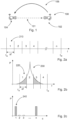
- the Figure 1 schematically outlines a microwave barrier 100 of a microwave barrier of a microwave barrier system with a microwave transmitting unit 104 and a microwave receiving unit 102, which is set up with a communication unit to signally couple the microwave receiving unit 102 to the microwave transmitting unit 104 106 in order to operate Channel for the operation of the microwave barrier 100 from the microwave receiving unit 102 to the microwave transmitter unit 104.
- the microwave receiving unit 102 and the microwave transmitter unit 104 are operationally coupled for the operation of the microwave barrier via a coupling path 101 in which microwave radiation from the microwave transmitting unit 104 is directed to the microwave receiving unit 102, in particular around an object in the coupling -Path 101 to detect.
- the microwave receiving unit 102 may scan a portion or all of the available microwave operating channels while the microwave transmitting unit 104 is deactivated to determine a respective foreign signal amplitude in at least a portion of the available microwave operating channels.
- the specific external signal amplitude can be caused by other neighboring microwave barriers or come from other radio services. However, both causes could disrupt the operation of the microwave barrier.
- the microwave receiving unit 102 When the microwave receiving unit 102 has determined a suitable microwave operating channel in order to minimize interference when operating the microwave barrier due to external signals, it transmits the microwave operating channel to the microwave transmitting unit 104 via the communication unit to the microwave transmitting unit the respective microwave barrier.
- the Figure 2a schematically outlines a value range of microwave frequencies f that are permitted for operation of a microwave barrier, with a lower frequency fu and an upper frequency fo, which are divided into a number of n microwave frequency channels with a respective width of ⁇ f.
- a microwave operating channel in this value range of microwave frequencies f can be assigned to a respective microwave barrier in a microwave barrier system in order to minimize mutual interference between the microwave barriers.
- the Figure 2b schematically sketches a diagram with microwave operating channels accordingly Figure 2a , whereby the permissible frequency range between a lower frequency fu and an upper frequency fo was divided into four microwave operating channels.
- a power or a power spectrum P 230 of a microwave transmitter unit of a microwave barrier is plotted above the frequency, to which a microwave operating channel with the number 2 has been assigned and which accordingly emits microwave radiation in the second channel. Due to the finite width of the power spectrum of the microwave radiation 220 of the microwave transmitter unit, microwave radiation can be omitted in the adjacent first channel 220 and the adjacent third channel, which has a signal/noise ratio for a microwave barrier whose microwave transmitter unit in the adjacent microwave operating unit. channels is operated, deteriorates.
- the Figure 2c schematically outlines a performance diagram in which a specific microwave power P, which was determined, for example, by the microwave reception unit 102 of a microwave barrier, is plotted over a large number n of available microwave operating channels c 240.
- a high power value is plotted in the first and nth channels c 240, which can each be caused, for example, by microwave radiation from a different microwave barrier.
- an external signal amplitude can be determined for each, or only for a part, of the large number of available frequency channels c 240 in order to determine a microwave operating channel for the operation of the microwave barrier, so that disruptions in the operation of the microwave barrier caused by external signals and/or other microwave barriers of the microwave barrier system are minimized.
- the microwave operating channel can be determined with an available microwave operating channel that has a minimum extraneous signal amplitude.
- the Figure 3 schematically outlines a system of four microwave barriers 302, 304, 306 and 308 with a first microwave barrier 302 and a second microwave barrier 304 within a system of four microwave barriers 302, 304, 306 and 308 operating adjacently.
- the respective microwave barrier 302, 304, 306 and 308 can have a microwave transmitter unit with an electrically tunable microwave generator and is set up to be operated with a selectable microwave frequency.
- the microwave receiving unit can be set up accordingly with an electrically tunable microwave generator in order to selectively determine a microwave signal from the respective microwave transmitting unit in relation to a detected microwave frequency.
- a position of an object 305 can be detected depending on the position of the object 305 in the respective coupling paths 301 of the respective microwave barriers 302, 304, 306 and 308 of the system of microwave barriers 302, 304, 306 and 308.
- the object 305 can interact with a respective coupling path 301 between the respective microwave transmitting unit and a respective assigned receiving unit in such a way that a microwave signal emitted by the respective microwave transmitting unit in the direction of the respective receiving unit is attenuated.
- the four microwave barriers 302, 304, 306 and 308 are set up by means of a communication unit, each of which is symbolized with a radio signal, to transmit a specific microwave operating channel from the microwave receiving unit of the respective microwave barrier 302, 304, 306 and 308 to the respective one Microwave transmitter unit and at least the respective microwave reception units of the four microwave barriers 302, 304, 306 and 308 are set up to be coupled to one another in terms of signals in order to, according to a master-slave method, the respective operating channels of the four microwave barriers 302, 304, 306 and 308 and to minimize interference when operating the system of the four microwave barriers 302, 304, 306 and 308.
- the respective microwave barrier 302, 304, 306 and 308 can be set up, in particular in a start sequence, for selecting an operating channel for the respective microwave barrier, for at least part of a stored plurality of available frequency channels for microwave barriers, an external signal amplitude by means of the the respective microwave receiving unit.
- the respective microwave receiving unit can scan all available frequency channels while the respective, or all, microwave transmitting units are deactivated in order to determine a respective external signal amplitude in at least some of the available frequency channels.
- the signal in frequency channel 1 or n can either be caused by other neighboring microwave barriers or come from other radio services. However, both can disrupt the operation of the microwave barrier system.
- a respective microwave operating channel can be selected for the respective microwave barrier based on the at least one specific external signal amplitude of the available frequency -Channels are determined in order to minimize interference when operating the first microwave barrier caused by an external signal.
- the transmission of the specific operating channel to the respective microwave transmission unit of the microwave barriers 302, 304, 306 and 308 and the signal coupling of the microwave barriers 302, 304, 306 and 308 to one another can be done by wire and/or wirelessly, in particular wirelessly via Bluetooth and/or or via microwaves, in particular the microwaves of the microwave barrier, and/or WLAN.
- microwave barriers 302, 304, 306 and 308 By coupling the microwave barriers 302, 304, 306 and 308 to one another in terms of signals, for example in a master-slave method and/or by means of a separate evaluation unit, a corresponding microwave operating channel can be determined for each microwave barrier in order to avoid disruptions in the operation of the System of four Microwave barriers 302, 304, 306 and 308 are minimized by an external signal and transmitted to the respective microwave transmitter unit.
- the external signals determined by the microwave barriers 302, 304, 306 and 308 can be transmitted to the evaluation unit or a master in order to determine the operating channels for the respective microwave barriers 302, 304, 306 and 308 and to the respective microwave barrier and/or the respective microwave transmitter units.
- the respective microwave barrier can be set up to be signal-coupled in a system of microwave barriers with all microwave transmitting units and all microwave receiving units of the system of microwave barriers in order to communicate with one another.
- One of the microwave receiving units can be set up as a master to determine the operating channels for the respective microwave barriers 302, 304, 306 and 308 and to transmit them to the respective microwave barriers 302, 304, 306 and 308 or their microwave transmitting units.
- the specific external signal amplitudes can be taken into account for determining the respective operating channels for the respective microwave barriers 302, 304, 306 and 308.
- Interfering radiation caused by the operation of one of the microwave transmitter units of the microwave barriers can be interpreted as an external signal amplitude.
- the respective operating channels can be assigned in such a way that frequency channels that are not adjacent in terms of frequency are assigned to spatially adjacent microwave barriers.
- the operating channels can be determined in a further improved manner, taking into account external signal amplitudes and interference radiation from the microwave transmission units involved, in order to minimize interference. This can prevent interference signals from other microwave transmitter units or other microwave sources from causing the system of microwave barriers to malfunction.
- channel 1 is assigned to the microwave barrier 302;
- Channel 3 is assigned to the microwave barrier 304;
- channel 5 is assigned to the microwave barrier 306; and
- channel 2 is assigned to the microwave barrier 308.
- the microwave frequency channels 1 to 5 are in ascending frequency sequence arranged adjacent to one another in a microwave frequency range, in particular between a lower frequency fu and an upper frequency fo.
- the Figure 4 schematically outlines a microwave barrier system with four microwave transmitting units 510 to 540 and a single receiving unit 550, the single receiving unit 550 being the receiving unit for all microwave barriers 510 to 540 of the microwave barrier system.
- the respective microwave transmitting unit 510 to 540 is set up to generate a microwave signal that is modulated and/or is coupled to the receiving unit 550 by means of different microwave frequency channels.
- the receiving unit 550 is set up to selectively detect an attenuation of the microwave signal based on the modulated microwave signal and/or according to the assigned microwave frequency channel.
- the Figure 5 schematically outlines a block diagram of a transmitter of a microwave transmission unit of a microwave barrier, which is set up to be operated with a selectable microwave frequency.
- VCO voltage controlled oscillator
- the voltage-controlled microwave oscillator 601 is tuned via a control voltage Ut generated by the PLL module 602 and by means of a loop filter 604, the loop filter 604 being coupled to both the PLL module 602 and to the voltage-controlled microwave oscillator 601.
- the control loop is closed by a part of the output signal of the voltage-controlled microwave oscillator 601 by means of an output of the voltage-controlled microwave oscillator 601 electrically coupled coupler 605 and is fed to the PLL module 602 by means of an optional prescaler 606 electrically coupled to the coupler 605.
- This signal is compared with the signal of the reference oscillator 603 by means of the PLL module 602 in a phase comparator of the PLL module 602.
- phase difference arising in the phase comparator between the two input signals of the PLL module 602, namely from the reference oscillator 603 and the output of the voltage-controlled microwave oscillator 601, is immediately compensated for again by the control, so that a very stable and low-noise microwave transmission signal is produced by means of the voltage-controlled microwave oscillator 601 is generated.
- the programming of the PLL module 602 and thus also the frequency setting of the microwave transmission signal, which is fed to a transmission antenna 607 via the coupler 605, is preferably carried out using a microcontroller 608 or another processor unit.
- Many voltage controlled oscillators on the market have internal couplers and prescalers. In this case, the coupler 605 and the prescaler 606 are eliminated as separate components and the voltage-controlled microwave oscillator 601 has an additional prescaler output, which in turn is electrically coupled to the PLL component.
- a change in the transmission channel is programmed into the PLL module 602 using the processor 608.
- the control circuit described above ensures that the voltage-controlled microwave oscillator 601 is quickly tuned to the new desired microwave frequency and thus also the microwave barrier to a new microwave frequency channel.
- the Figure 6 schematically outlines a block diagram of a receiver of a receiving unit of a microwave barrier, which is set up to selectively detect attenuation of the microwave signal based on an assigned microwave frequency channel.
- the oscillator circuit 600 corresponds to the oscillator circuit 600 of the Figure 5 .
- This oscillator circuit 600 is thus set up to generate a local oscillator (LO) signal for a mixer 709.
- a corresponding received signal which is received by the receiving antenna 710, is mixed down with the LO signal in the mixer 709 into a much lower-frequency intermediate frequency signal.
- the frequency difference between LO signal and received signal is a fixed value and determines the frequency of the intermediate frequency signal.
- the intermediate frequency signal then passes through a bandpass filter 711 and is amplified in an intermediate frequency amplifier 712.
- the signal is then sampled in an AD converter 713, for example, and the received level is further processed and evaluated in the processor 608.
- a logarithmic amplifier can also be used.
- the frequency tuning of the receiver circuit to different microwave frequency channels is carried out in the same way as in the transmitter circuit 600. Sequential tuning to the channels used is also carried out for selectively receiving different microwave frequency channels, as is done, for example, by the receiving unit, which is carried out by means of the Figure 5 is described can be realized thereby.
- the entire frequency spectrum used in the respective permitted frequency band can also be mixed into the intermediate frequency range.
- the prerequisite here is that the bandpass filter 711 and the subsequent components in the signal path are “wide” enough to be able to process the respective frequency band together.
- the intermediate frequency signal can be sampled and transformed from the time domain into the frequency domain using a Fourier transformation. From the resulting intermediate frequency spectrum, the reception levels can then be selectively assigned to the individual channels used.
- the transmitter circuit 600 of the Figure 5 or 6 can be made from individual components or integrated into an integrated circuit. This applies in particular to the components: voltage-controlled microwave oscillator 601; PLL module 602; loop filter 604; coupler 605; Prescaler 606 and the processor 608, which are predestined to be integrated on a common chip.
- Figure 6 Information can be applied by means of, for example, FSK (FSK: Frequency Shift Keying) or PSK (PSK: Phase Shift Keying) modulation or other types of modulation.
- FSK Frequency Shift Keying
- PSK Phase Shift Keying
Landscapes
- Physics & Mathematics (AREA)
- Life Sciences & Earth Sciences (AREA)
- General Life Sciences & Earth Sciences (AREA)
- General Physics & Mathematics (AREA)
- Geophysics (AREA)
- Engineering & Computer Science (AREA)
- Remote Sensing (AREA)
- Electromagnetism (AREA)
- Environmental & Geological Engineering (AREA)
- Geology (AREA)
- Radar Systems Or Details Thereof (AREA)
Applications Claiming Priority (2)
| Application Number | Priority Date | Filing Date | Title |
|---|---|---|---|
| EP22178491.1A EP4290192A1 (fr) | 2022-06-10 | 2022-06-10 | Procédé de sélection d'un canal de fonctionnement pour une barrière à micro-ondes |
| EP22178479.6A EP4290279A1 (fr) | 2022-06-10 | 2022-06-10 | Système barrière à micro-ondes |
Publications (1)
| Publication Number | Publication Date |
|---|---|
| EP4290280A1 true EP4290280A1 (fr) | 2023-12-13 |
Family
ID=86609738
Family Applications (1)
| Application Number | Title | Priority Date | Filing Date |
|---|---|---|---|
| EP23178107.1A Pending EP4290280A1 (fr) | 2022-06-10 | 2023-06-07 | Système de confinement de micro-ondes |
Country Status (2)
| Country | Link |
|---|---|
| US (1) | US12498503B2 (fr) |
| EP (1) | EP4290280A1 (fr) |
Citations (3)
| Publication number | Priority date | Publication date | Assignee | Title |
|---|---|---|---|---|
| US20130252553A1 (en) * | 2012-03-23 | 2013-09-26 | Samsung Electronics Co., Ltd. | Ultra-low power wireless communication apparatus and method |
| DE102013100817A1 (de) * | 2013-01-28 | 2014-07-31 | Sick Ag | Mikrowellenschranke und Verfahren zur Erkennung eines Objekts in einem Mikrowellenpfad |
| EP3139139A1 (fr) * | 2015-09-01 | 2017-03-08 | VEGA Grieshaber KG | Appareil de mesure de niveau de remplissage avec mode de détection de signaux parasites |
Family Cites Families (8)
| Publication number | Priority date | Publication date | Assignee | Title |
|---|---|---|---|---|
| DE2539438C3 (de) | 1975-09-04 | 1979-02-01 | Erwin Sick Gmbh Optik-Elektronik, 7808 Waldkirch | Strahlenschranke |
| DE3302731A1 (de) | 1983-01-27 | 1984-08-02 | VEGA Grieshaber GmbH & Co, 7620 Wolfach | Mikrowellenschranke |
| DE60108118D1 (de) * | 2001-08-16 | 2005-02-03 | Tecno Alarm S N C | Einbruch-Detektierungssystem mit einer Microwellenschranke |
| DE102009033435A1 (de) | 2009-07-16 | 2011-01-20 | Leuze Electronic Gmbh & Co Kg | Verfahren zum Betrieb von Lichtschranken |
| DE102013220131B4 (de) | 2013-10-04 | 2022-03-24 | Rohde & Schwarz GmbH & Co. Kommanditgesellschaft | Bildgebungssystem mit orthogonalen Sendesignalen |
| EP3258296B1 (fr) * | 2016-06-14 | 2023-07-26 | VEGA Grieshaber KG | Barriere de micro-ondes de reflexion |
| US11029187B2 (en) | 2017-06-21 | 2021-06-08 | Vega Grieshaber Kg | Fill level reflectometer having a variable measurement sequence |
| EP3575755B1 (fr) | 2018-05-28 | 2023-10-25 | VEGA Grieshaber KG | Appareil de mesure de niveau de remplissage à commande d'antenne optimisée et méthode de mesure de niveau |
-
2023
- 2023-06-07 EP EP23178107.1A patent/EP4290280A1/fr active Pending
- 2023-06-09 US US18/332,383 patent/US12498503B2/en active Active
Patent Citations (3)
| Publication number | Priority date | Publication date | Assignee | Title |
|---|---|---|---|---|
| US20130252553A1 (en) * | 2012-03-23 | 2013-09-26 | Samsung Electronics Co., Ltd. | Ultra-low power wireless communication apparatus and method |
| DE102013100817A1 (de) * | 2013-01-28 | 2014-07-31 | Sick Ag | Mikrowellenschranke und Verfahren zur Erkennung eines Objekts in einem Mikrowellenpfad |
| EP3139139A1 (fr) * | 2015-09-01 | 2017-03-08 | VEGA Grieshaber KG | Appareil de mesure de niveau de remplissage avec mode de détection de signaux parasites |
Non-Patent Citations (1)
| Title |
|---|
| ANONYMOUS: "Technical Information Soliwave FDR56/FQR56 Microwave barrier", 27 August 2018 (2018-08-27), pages 1 - 48, XP055979731, Retrieved from the Internet <URL:https://portal.endress.com/wa001/dla/5001113/1085/000/07/TI00443FEN_1618.pdf> [retrieved on 20221109] * |
Also Published As
| Publication number | Publication date |
|---|---|
| US20230400600A1 (en) | 2023-12-14 |
| US12498503B2 (en) | 2025-12-16 |
Similar Documents
| Publication | Publication Date | Title |
|---|---|---|
| DE60037568T2 (de) | Zweibandtelemetriesystem | |
| DE69734338T2 (de) | Zweibandsendeempfänger | |
| EP3139139B1 (fr) | Appareil de mesure de niveau de remplissage avec mode de détection de signaux parasites | |
| DE60130078T2 (de) | Drahtlose Kommunikationskanalselektion mittels passiven Interferenzvermeidungsverfahren | |
| DE2748746C2 (fr) | ||
| DE69427718T2 (de) | Funksender/Empfänger für Zeitduplex | |
| DE4498745B4 (de) | Funkfrequenztransceiver und Verfahren zum Betrieb desselben | |
| EP0806849A2 (fr) | Circuit pour le contrÔle du bon fonctionnement de systèmes de réception mobiles | |
| EP0438075A2 (fr) | Système optique de transmission de télévision par câble | |
| DE3415032A1 (de) | Verfahren zur stoerresistenten funkuebertragung | |
| DE69133358T2 (de) | Ton-im-Band-Übertragungssystem mit verschobenem Pilotton | |
| DE69903856T2 (de) | Funknachrichteneinheit | |
| DE3008684A1 (de) | Verfahren und schaltungsanordnung zur nachrichtenuebertragung in zwei richtungen | |
| DE69922584T2 (de) | Hochfrequenzumsetzer | |
| DE4005517C2 (fr) | ||
| DE2450860C2 (de) | Verfahren zur Sicherung eines der Frequenzregelung dienenden Pilotsignals in einem Nachrichtenübertragungssystem und Einrichtung in einer Bodenstation zur Durchführung des Verfahrens | |
| DE102014112920B4 (de) | Sensorsysteme und Verfahren unter Verwendung von Bandpassfilterabstimmung | |
| EP4290280A1 (fr) | Système de confinement de micro-ondes | |
| DE60123956T2 (de) | Selbstabgleichende bandpassfilterungsvorrichtung in einem sende-empfangsgerät für mikrowellensignale | |
| DE60121247T2 (de) | Empfänger mit einem Synthesizer | |
| EP1013007A1 (fr) | Dispositif d'emission et de reception pour l'amplification entre des stations fixes et des stations mobiles avec detection du canal radio | |
| EP4290279A1 (fr) | Système barrière à micro-ondes | |
| DE964691C (de) | Relaisstation | |
| DE69222279T2 (de) | TDMA-TDD Sender-Empfänger | |
| EP0715424B1 (fr) | Procédé de test d'un système radio |
Legal Events
| Date | Code | Title | Description |
|---|---|---|---|
| PUAI | Public reference made under article 153(3) epc to a published international application that has entered the european phase |
Free format text: ORIGINAL CODE: 0009012 |
|
| STAA | Information on the status of an ep patent application or granted ep patent |
Free format text: STATUS: THE APPLICATION HAS BEEN PUBLISHED |
|
| AK | Designated contracting states |
Kind code of ref document: A1 Designated state(s): AL AT BE BG CH CY CZ DE DK EE ES FI FR GB GR HR HU IE IS IT LI LT LU LV MC ME MK MT NL NO PL PT RO RS SE SI SK SM TR |
|
| STAA | Information on the status of an ep patent application or granted ep patent |
Free format text: STATUS: REQUEST FOR EXAMINATION WAS MADE |
|
| 17P | Request for examination filed |
Effective date: 20240425 |
|
| RBV | Designated contracting states (corrected) |
Designated state(s): AL AT BE BG CH CY CZ DE DK EE ES FI FR GB GR HR HU IE IS IT LI LT LU LV MC ME MK MT NL NO PL PT RO RS SE SI SK SM TR |
|
| STAA | Information on the status of an ep patent application or granted ep patent |
Free format text: STATUS: EXAMINATION IS IN PROGRESS |
|
| 17Q | First examination report despatched |
Effective date: 20251113 |
|
| GRAP | Despatch of communication of intention to grant a patent |
Free format text: ORIGINAL CODE: EPIDOSNIGR1 |
|
| STAA | Information on the status of an ep patent application or granted ep patent |
Free format text: STATUS: GRANT OF PATENT IS INTENDED |