EP3258331A1 - Procede destine a la surveillance d'une machine - Google Patents
Procede destine a la surveillance d'une machine Download PDFInfo
- Publication number
- EP3258331A1 EP3258331A1 EP16305737.5A EP16305737A EP3258331A1 EP 3258331 A1 EP3258331 A1 EP 3258331A1 EP 16305737 A EP16305737 A EP 16305737A EP 3258331 A1 EP3258331 A1 EP 3258331A1
- Authority
- EP
- European Patent Office
- Prior art keywords
- motor
- friction
- determined
- torque
- mech
- Prior art date
- Legal status (The legal status is an assumption and is not a legal conclusion. Google has not performed a legal analysis and makes no representation as to the accuracy of the status listed.)
- Granted
Links
Images

Classifications
-
- H—ELECTRICITY
- H02—GENERATION; CONVERSION OR DISTRIBUTION OF ELECTRIC POWER
- H02P—CONTROL OR REGULATION OF ELECTRIC MOTORS, ELECTRIC GENERATORS OR DYNAMO-ELECTRIC CONVERTERS; CONTROLLING TRANSFORMERS, REACTORS OR CHOKE COILS
- H02P23/00—Arrangements or methods for the control of AC motors characterised by a control method other than vector control
- H02P23/14—Estimation or adaptation of motor parameters, e.g. rotor time constant, flux, speed, current or voltage
-
- G—PHYSICS
- G05—CONTROLLING; REGULATING
- G05B—CONTROL OR REGULATING SYSTEMS IN GENERAL; FUNCTIONAL ELEMENTS OF SUCH SYSTEMS; MONITORING OR TESTING ARRANGEMENTS FOR SUCH SYSTEMS OR ELEMENTS
- G05B19/00—Program-control systems
- G05B19/02—Program-control systems electric
- G05B19/04—Program control other than numerical control, i.e. in sequence controllers or logic controllers
- G05B19/042—Program control other than numerical control, i.e. in sequence controllers or logic controllers using digital processors
- G05B19/0428—Safety, monitoring
-
- G—PHYSICS
- G05—CONTROLLING; REGULATING
- G05B—CONTROL OR REGULATING SYSTEMS IN GENERAL; FUNCTIONAL ELEMENTS OF SUCH SYSTEMS; MONITORING OR TESTING ARRANGEMENTS FOR SUCH SYSTEMS OR ELEMENTS
- G05B19/00—Program-control systems
- G05B19/02—Program-control systems electric
- G05B19/18—Numerical control [NC], i.e. automatically operating machines, in particular machine tools, e.g. in a manufacturing environment, so as to execute positioning, movement or co-ordinated operations by means of program data in numerical form
- G05B19/404—Numerical control [NC], i.e. automatically operating machines, in particular machine tools, e.g. in a manufacturing environment, so as to execute positioning, movement or co-ordinated operations by means of program data in numerical form characterised by control arrangements for compensation, e.g. for backlash, overshoot, tool offset, tool wear, temperature, machine construction errors, load, inertia
Definitions
- the present invention relates to a method for monitoring a machine in which a motor drives a mechanism.
- control parameters are set in particular in the device of the machine in a motor control, which indicate mechanical characteristics of the machine or the mechanism.
- the underlying values are estimated and / or determined based on empirical values.
- the originally set values of the control parameters can then no longer be valid so that malfunctions or overloads can occur.
- the invention is based on the recognition that the moment of inertia of the mechanism and the friction of the mechanism can be calculated on the basis of the determination of the torque delivered by the engine to the mechanism and the determination of the angular acceleration of the engine.
- the calculation of the moment of inertia of the mechanics and the friction of the mechanics can be done in a motor control. Calculation options are explained below.
- the torque delivered by the engine to the mechanics as well as the angular acceleration of the motor can each be measured directly or calculated from another measured variable.
- both the determined torque output by the engine to the mechanism and the angular acceleration of the motor are preferably based on a measured quantity.
- a linear acceleration of the mechanism can be measured, whereupon can be calculated back to the angular acceleration of the engine.
- the calculated moment of inertia of the mechanism and the friction of the mechanism are thus based on measured values, whereby an adjustment of the motor control no longer has to be based on estimated values, but can be done on the basis of measured values and thus on the basis of the actual mechanical properties of the mechanism.
- the inventive method can be performed at any time throughout the life cycle of the machine.
- the method is independent of the instantaneous speed, angular acceleration or power of the engine, which means that a "normal" operation of the machine does not have to be interrupted in order to carry out the method.
- parameters to be used initially during the device setup can be determined.
- a dimensioning of the motor can be changed in order to use a matching engine to the engine.
- the parameters may be repeatedly checked (e.g., at fixed intervals) and changed if necessary.
- a warning signal can be issued with which a precautionary maintenance of the machine can be made.
- the method according to the invention makes it possible in a simple way to achieve a higher accuracy in the continuous determination and adaptation of the mechanical parameters of a machine in comparison to methods according to the prior art.
- M J * ⁇ + M mech calculated.
- M denotes the torque delivered by the engine to the mechanism
- J the moment of inertia of the mechanism
- ⁇ the angular acceleration of the motor
- M mech the friction of the mechanism.
- the torque output by the engine to the mechanics and the respective angular acceleration of the engine are preferably determined in at least two different operating states of the engine.
- the operating states can be chosen arbitrarily.
- the unknown quantities are the moment of inertia (J) of the mechanics and the friction (M mech ) of the mechanics.
- the determination of the output from the engine to the mechanics torque and the angular acceleration of the engine is such that the determined angular acceleration and the detected torque are assigned to each other, that is, for example, be determined at the same time and / or come from the same operating condition.
- an operating condition in particular an operating point of the machine can be understood, that is a specific combination, for example, of a rotational frequency of the motor, an angular acceleration of the motor and / or a power consumption of the motor.
- the moment of inertia of the mechanism and / or the friction of the mechanism are determined by means of a regression analysis, wherein in particular in a variety of different operating conditions, the respective output from the engine to the mechanics torque and the respective angular acceleration of the engine are determined.
- a "cloud" of measuring points can be generated in a coordinate system in which the abscissa represents the angular acceleration of the motor and the ordinate the torque output by the motor to the mechanics.
- a straight line is preferably laid by the point cloud, from which the straight-line equation is subsequently determined. With the straight-line equation, as explained above, the moment of inertia (J) of the mechanism and the friction (M mech ) of the mechanism are known.
- the torque delivered by the engine to the mechanism is calculated on the basis of a current (I) received by the motor and / or a power consumed by the motor.
- a current of an inverter coupled to the motor can be detected or measured.
- the motor By measuring the current consumed by the motor, the motor is not only used to drive the mechanics, but also serves as a measuring device to determine characteristics of the mechanics.
- the torque delivered by the motor to the mechanism can also be measured directly, for example with a torque transducer, by means of strain gauges or by means of optical encoders which detect the torsion of a shaft.
- the angular acceleration of the motor is calculated on the basis of an acceleration (a) of a translatory or linear movement of the mechanism, in particular by a multiplication of the acceleration (a) by 2 * ⁇ and a subsequent division by a feed constant (K V ).
- K V feed constant
- the determination of the angular acceleration from a translational or linear movement may be advantageous if the mechanism comprises a component driven by the motor, which performs such a movement.
- the speed or acceleration of the translatory or linear movement can be determined by incremental encoders.
- the friction (M mech ) of the mechanism comprises a static friction (M additive ).
- the static friction is essentially independent of a current rotational frequency of the motor or a momentary angular acceleration of the motor.
- the friction of the mechanism only comprises a static friction or to determine the friction of the mechanism, it is assumed that the friction of the mechanism is exclusively a static friction.
- the friction of the mechanism comprises a viscous friction (M visk ), which depends on a rotational speed ( ⁇ ) of the motor.
- M visk a viscous friction
- the rotational speed ( ⁇ ) of the motor can also be referred to as the angular speed of the motor.
- three sets of torque (M), angular acceleration ( ⁇ ) and rotational speed ( ⁇ ) can be obtained for three different operating conditions. From the values thus determined, the moment of inertia (J) of the mechanism and the static friction (M additive ) as well as the viscous friction (M visk ) of the mechanism can be determined. For this purpose, for example, a system of equations of three equations and three unknowns can be set up. Based on the three sets of determined values, this system of equations can be solved.
- a plurality of measurements can be carried out, wherein in each case the output from the engine to the mechanics torque, the angular acceleration of the motor and the rotational frequency of the motor are determined as respective associated (measurement) values. These values can then be plotted in a three-dimensional coordinate system ( ⁇ , ⁇ , M coordinate system).
- ⁇ , ⁇ , M coordinate system By means of a regression analysis, a plane can be laid in the resulting point cloud of values, whereby the inertia moment (J) of the mechanics, the static friction (M addition ) and the viscous friction (M visk ) are known on the basis of the plane equation.
- the moment of inertia of the mechanism and / or the friction of the mechanism are repeatedly redetermined.
- an activation of the motor For example, a maximum allowable current of the motor can be increased or decreased to be adapted to the conditions of the mechanics. Also parameters of a control circuit for the engine can be changed.
- a determination of the moment of inertia of the mechanism and / or the friction of the mechanism can in particular be made cyclically.
- the moment of inertia of the mechanism and / or the friction of the mechanism are determined at least every 10 seconds, preferably at least every second.
- the determination can only require a few milliseconds each.
- the determination can be made, in particular, when an operating state of the engine is changed, for example by driving a ramp (or any other format).
- a control of the engine is adapted to the calculated moment of inertia of the mechanism and / or the calculated friction of the mechanism, in particular (as already stated) by an adaptation of control parameters.
- the calculated values can thus serve to achieve an improved or more suitable control of the motor.
- a warning signal is generated on the basis of the calculated moment of inertia of the mechanism and / or on the basis of the calculated friction of the mechanism, which announces the imminence of maintenance of the mechanism.
- a threshold value can be specified for the friction of the mechanism (and here also for the static and / or viscous friction). Once this threshold is exceeded, the warning signal can be issued to perform a predictive maintenance of the mechanics or a check of the mechanics. It is advantageous that due to the warning signal errors in the machine or in the mechanics can be detected early and overloading of the engine, for example by impressing too high a current, can be avoided.
- the invention relates to a machine with a motor and a mechanism driven by the engine.
- the machine is characterized in that it is designed to carry out a method of the type described above.
- the machine comprises a control unit which controls the motor and calculates the moment of inertia of the mechanism and the friction of the mechanism.
- the motor is an electric motor and in particular a servomotor with a gear and a rotary encoder.
- the rotary encoder By means of the rotary encoder, both the rotational speed ( ⁇ ) and the angular acceleration ( ⁇ ) of the motor can be measured.
- Both a torque constant (K M ) of the engine and a transmission factor (i) of the transmission can be known for this purpose.
- the torque constant (K M ) of the motor and / or the gear factor (i) are constant.
- the machine comprises a measuring device which transmits a torque (M) delivered by the motor to the mechanism and / or a current (I) picked up by the motor and / or a power of the motor and / or a rotational speed ( ⁇ ). of the engine and / or an angular acceleration ( ⁇ ) of the motor determined.
- M torque
- I current
- ⁇ rotational speed
- the machine comprises a measuring device which determines an acceleration of the mechanism.
- the acceleration of the mechanism may in particular be an acceleration of a translatory or linear movement.
- This translatory movement can be converted into an angular acceleration of the motor by means of a feed constant (K V ).
- the feed constant (K V ) indicates, in particular, how large a translatory or linear movement of the mechanism takes place per revolution of the motor.
- the mechanism is a conveyor belt.
- the conveyor belt can perform a translatory movement and, for example, transport objects in a manufacturing process in an industrial plant. If, for example, the transported objects are grinding at a boundary of the conveyor belt, the friction of the mechanism is increased, which can be determined. Because of the knowledge of the increased friction, then the cause of the increased friction can be eliminated.
- the mechanics can basically be any parts driven or driven by a motor.
- the mechanism may comprise a robot arm, a gripper, the already mentioned conveyor belt and / or a driving wheel of a vehicle and the like.
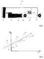
- FIG. 10 shows a machine 10 including a motor controller 12 and a servomotor 14 electrically connected to the motor controller 12.
- the servomotor 14 drives via a gear 16 by means of a rotatable shaft 18, a mechanism in the form of a conveyor belt 20 selected here by way of example. With the conveyor belt 20, a load 22 can be moved.
- a motion sensor 24 is mounted, which is connected to the motor controller 12.
- the motion sensor 24 determines a speed and an acceleration of the conveyor belt 20 and transmits these values to the engine controller 12.
- the motor controller 12 calculates an angular acceleration ⁇ of the servo motor 14 by means of a feed constant K V from the acceleration of the conveyor belt 20. In addition, the motor controller 12 detects a current picked up by the servomotor 14 and a torque constant K M of the motor from the motor to the mechanics output torque M. The output torque M is transmitted by means of the shaft 18 to the conveyor belt 20.
- the engine control unit 12 determines the output torque M and the angular acceleration ⁇ in various operating situations (ie operating states) of the engine 10 and enters the torque M with respect to the associated angular acceleration ⁇ as first measured values 26 into a two-dimensional coordinate system, as shown in FIG Fig. 2 is shown.
- the angular acceleration ⁇ is plotted on the abscissa and the output torque M is plotted on the ordinate.
- the first measured values 26 form a first point cloud 28 into which a straight line 30 is inserted by means of a regression analysis by the motor control 12. From the straight line 30, a first pitch 31 and an intercept 32 are determined.
- the first slope 31 is shown as a gradient triangle, wherein the first slope 31 of the moment of inertia J of the mechanism, that is, the moment of inertia J of the conveyor belt 20, corresponds.
- the axis section 32 corresponds to a static friction M addition of the mechanics.
- the motor control 12 can correspondingly change the control parameters for the control of the servomotor 14. If the friction of the mechanism exceeds a predetermined threshold value, a warning signal can be issued which can lead to maintenance of the conveyor belt 20.
- a rotational speed ⁇ of the motor are taken into account.
- the rotational speed ⁇ of the motor can be determined by means of a speed v of the conveyor belt 20 via the feed constant K V.
- the rotational speed ⁇ corresponds to the speed v multiplied by 2 ⁇ divided by the feed constant Kv.
- Corresponding measured values of rotational speed ⁇ of servo motor 14, angular acceleration ⁇ of servomotor 14 and torque M delivered by servo motor 14 to conveyor belt 20 can then be converted into a three-dimensional Cartesian coordinate system (FIG. Fig. 3 ), in which the mutually perpendicular axes represent the angular acceleration ⁇ , the rotational speed ⁇ and the output torque M.
- the measured values can each be entered as second measured values 34 in the three-dimensional coordinate system and form a second point cloud 36.
- the second point cloud 36 may be regression-analyzed by the engine controller 12 to write a plane 38 into the second point cloud 36.
- the first slope 31 can then be determined in the direction of the angular acceleration ⁇ .
- the first slope 31 corresponds to the moment of inertia J of the conveyor belt 20.
- a second slope 39 in FIG Direction of the rotation speed ⁇ corresponding to the viscous friction M Visc of the conveyor belt 20.
- a distance of the intersection of plane 38 with the torque M representing the axis from the origin of the three-dimensional coordinate system (corresponding to the axis portion 32) is the static frictional M addition of the conveyor belt 20 at.
- the engine controller 12 may generate and evaluate the first and / or second measurements 26, 34 and evaluate them in the manner explained.
- the values determined for the evaluation of the moment of inertia J of the mechanism, for the static friction M additive and the viscous friction M visk can then be used to adapt an activation of the servomotor 14 and / or by means of a warning signal for abnormalities or wear on the conveyor belt 20 to point out.
Landscapes
- Engineering & Computer Science (AREA)
- Physics & Mathematics (AREA)
- General Physics & Mathematics (AREA)
- Automation & Control Theory (AREA)
- Power Engineering (AREA)
- Human Computer Interaction (AREA)
- Manufacturing & Machinery (AREA)
- Control Of Electric Motors In General (AREA)
Priority Applications (1)
| Application Number | Priority Date | Filing Date | Title |
|---|---|---|---|
| EP16305737.5A EP3258331B1 (fr) | 2016-06-16 | 2016-06-16 | Surveillance d'une machine |
Applications Claiming Priority (1)
| Application Number | Priority Date | Filing Date | Title |
|---|---|---|---|
| EP16305737.5A EP3258331B1 (fr) | 2016-06-16 | 2016-06-16 | Surveillance d'une machine |
Publications (2)
| Publication Number | Publication Date |
|---|---|
| EP3258331A1 true EP3258331A1 (fr) | 2017-12-20 |
| EP3258331B1 EP3258331B1 (fr) | 2025-12-31 |
Family
ID=56550814
Family Applications (1)
| Application Number | Title | Priority Date | Filing Date |
|---|---|---|---|
| EP16305737.5A Active EP3258331B1 (fr) | 2016-06-16 | 2016-06-16 | Surveillance d'une machine |
Country Status (1)
| Country | Link |
|---|---|
| EP (1) | EP3258331B1 (fr) |
Cited By (2)
| Publication number | Priority date | Publication date | Assignee | Title |
|---|---|---|---|---|
| CN112099424A (zh) * | 2019-06-17 | 2020-12-18 | 施耐德电器工业公司 | 用于监控机器的方法 |
| WO2024020018A1 (fr) * | 2022-07-18 | 2024-01-25 | Woodward, Inc. | Dispositif de surveillance de la santé d'une vanne en ligne |
Citations (4)
| Publication number | Priority date | Publication date | Assignee | Title |
|---|---|---|---|---|
| DE4111530A1 (de) * | 1990-04-09 | 1991-10-10 | Mitsubishi Electric Corp | Numerische steuereinheit und verfahren zur lageregelung eines motorgetriebenen beweglichen teils |
| DE102012106771A1 (de) * | 2011-07-27 | 2013-01-31 | Fanuc Corp. | Controller für elektromotor, umfassend eine funktion zum simultanen schätzen von trägheit, reibung und federkonstante |
| DE102011121839A1 (de) * | 2011-12-21 | 2013-06-27 | Robert Bosch Gmbh | Verfahren zur Bewegungssteuerung mit Trägheitsmoment - Ermittlung |
| WO2013158849A2 (fr) * | 2012-04-20 | 2013-10-24 | Linestream Technologies | Procédé d'estimation automatique d'inertie dans un système mécanique et de production d'un profil de mouvement |
Family Cites Families (1)
| Publication number | Priority date | Publication date | Assignee | Title |
|---|---|---|---|---|
| JPS56101533A (en) * | 1979-12-31 | 1981-08-14 | Ibm | Measurement unit for friction associated with motor |
-
2016
- 2016-06-16 EP EP16305737.5A patent/EP3258331B1/fr active Active
Patent Citations (4)
| Publication number | Priority date | Publication date | Assignee | Title |
|---|---|---|---|---|
| DE4111530A1 (de) * | 1990-04-09 | 1991-10-10 | Mitsubishi Electric Corp | Numerische steuereinheit und verfahren zur lageregelung eines motorgetriebenen beweglichen teils |
| DE102012106771A1 (de) * | 2011-07-27 | 2013-01-31 | Fanuc Corp. | Controller für elektromotor, umfassend eine funktion zum simultanen schätzen von trägheit, reibung und federkonstante |
| DE102011121839A1 (de) * | 2011-12-21 | 2013-06-27 | Robert Bosch Gmbh | Verfahren zur Bewegungssteuerung mit Trägheitsmoment - Ermittlung |
| WO2013158849A2 (fr) * | 2012-04-20 | 2013-10-24 | Linestream Technologies | Procédé d'estimation automatique d'inertie dans un système mécanique et de production d'un profil de mouvement |
Non-Patent Citations (1)
| Title |
|---|
| JAN BRAUN: "V CC Formelsammlung Formelsammlung Formelsammlung Formelsammlung Formelsammlung Formelsammlung Formelsammlung Formelsammlung Formelsammlung Formelsammlung Formelsammlung Formelsammlung Formelsammlung", 5 July 2012 (2012-07-05), XP055306972, Retrieved from the Internet <URL:http://www.maxonmotor.de/medias/sys_master/root/8819062800414/maxon-Formelsammlung-d.pdf?attachment=true> [retrieved on 20160930] * |
Cited By (5)
| Publication number | Priority date | Publication date | Assignee | Title |
|---|---|---|---|---|
| CN112099424A (zh) * | 2019-06-17 | 2020-12-18 | 施耐德电器工业公司 | 用于监控机器的方法 |
| EP3754837A1 (fr) * | 2019-06-17 | 2020-12-23 | Schneider Electric Industries SAS | Procédé de surveillance d'une machine |
| US11435402B2 (en) | 2019-06-17 | 2022-09-06 | Schneider Electric Industries Sas | Method of monitoring a machine |
| CN112099424B (zh) * | 2019-06-17 | 2024-05-07 | 施耐德电器工业公司 | 用于监控机器的方法 |
| WO2024020018A1 (fr) * | 2022-07-18 | 2024-01-25 | Woodward, Inc. | Dispositif de surveillance de la santé d'une vanne en ligne |
Also Published As
| Publication number | Publication date |
|---|---|
| EP3258331B1 (fr) | 2025-12-31 |
Similar Documents
| Publication | Publication Date | Title |
|---|---|---|
| EP2628575B1 (fr) | Procédé destiné à déterminer un couple et robot industriel | |
| DE112014005564B4 (de) | Reibungsidentifizierungsverfahren und Reibungsidentifizierungsgerät | |
| DE102010052261B4 (de) | Verfahren und Vorrichtung zum Kalibrieren einer Drehmomentenmesseinrichtung | |
| DE102007038890B4 (de) | Verfahren und Vorrichtung zur Bestimmung der Lebensdauer von im Arbeitsbetrieb befindlichen Bauteilen | |
| DE102019103557B4 (de) | Schwingungsanalysator und Schwingungsanalyseverfahren | |
| DE102017011740B4 (de) | Störungsermittlungsvorrichtung und Störungsermittlungsverfahren | |
| DE102014105681B4 (de) | Trägheitsschätzverfahren und trägheitsschätzvorrichtung einer positionssteuervorrichtung | |
| DE102008021849A1 (de) | Elektromechanisches Lenksystem mit Anpassung des Lenkwinkels der Räder an den Handwinkel | |
| EP3365737B1 (fr) | Determination de la rigidite d'une chaine cinematique d'une machine, en particulier d'une machine de production ou d'une machine-outil | |
| EP2023092B1 (fr) | Appareil de mesure de position et procédé de transmission d'une information de mouvement | |
| AT508031B1 (de) | Verfahren und prüfstand zur nachbildung des fahrverhaltens eines fahrzeugs | |
| DE19505561C2 (de) | Verfahren und Vorrichtung zur Schlupfregelung von Reibelementen oder Getrieben | |
| EP4381361B1 (fr) | Procédé, dispositif et programme informatique pour la détection d'une erreur dans la position réelle d'un essieu d'une machine | |
| EP3258331B1 (fr) | Surveillance d'une machine | |
| WO2011044607A1 (fr) | Procédé ainsi que banc d'essai pour contrôler une chaîne cinématique d'un véhicule | |
| DE102021113139B3 (de) | Verfahren zur Verwendung einer Robotereinrichtung; System; Computerprogramm; Speichermedium | |
| DE102017007978B4 (de) | Numerische Steuervorrichtung | |
| DE102011121839A1 (de) | Verfahren zur Bewegungssteuerung mit Trägheitsmoment - Ermittlung | |
| WO2007137886A1 (fr) | Dispositif destiné à suivre le mouvement d'un élément d'une machine | |
| DE102015111409B3 (de) | Verfahren zur Bestimmung von Kräften und/oder Drehmomenten | |
| WO2008092581A1 (fr) | Dispositif et procédé pour un test de fonctionnement d'un frein | |
| DE112021004831T5 (de) | Anomaliedetektionsvorrichtung, die anomalien in einem leistungsübertragungsmechanismus zum übertragen einer durch einen motor ausgegebenen drehkraft detektiert | |
| DE19634145A1 (de) | Arbeitsbereich-Beschränkungsverfahren bei einer Werkzeugmaschine | |
| EP2033056B1 (fr) | Procédé pour commander le déplacement d' un actionneur | |
| EP3754837B1 (fr) | Procédé de surveillance d'une machine |
Legal Events
| Date | Code | Title | Description |
|---|---|---|---|
| PUAI | Public reference made under article 153(3) epc to a published international application that has entered the european phase |
Free format text: ORIGINAL CODE: 0009012 |
|
| STAA | Information on the status of an ep patent application or granted ep patent |
Free format text: STATUS: THE APPLICATION HAS BEEN PUBLISHED |
|
| AK | Designated contracting states |
Kind code of ref document: A1 Designated state(s): AL AT BE BG CH CY CZ DE DK EE ES FI FR GB GR HR HU IE IS IT LI LT LU LV MC MK MT NL NO PL PT RO RS SE SI SK SM TR |
|
| AX | Request for extension of the european patent |
Extension state: BA ME |
|
| STAA | Information on the status of an ep patent application or granted ep patent |
Free format text: STATUS: REQUEST FOR EXAMINATION WAS MADE |
|
| 17P | Request for examination filed |
Effective date: 20180516 |
|
| RBV | Designated contracting states (corrected) |
Designated state(s): AL AT BE BG CH CY CZ DE DK EE ES FI FR GB GR HR HU IE IS IT LI LT LU LV MC MK MT NL NO PL PT RO RS SE SI SK SM TR |
|
| STAA | Information on the status of an ep patent application or granted ep patent |
Free format text: STATUS: EXAMINATION IS IN PROGRESS |
|
| 17Q | First examination report despatched |
Effective date: 20200603 |
|
| REG | Reference to a national code |
Ref country code: DE Ref legal event code: R079 Free format text: PREVIOUS MAIN CLASS: G05B0019404000 Ipc: G05B0019042000 Ref document number: 502016017117 Country of ref document: DE |
|
| RIC1 | Information provided on ipc code assigned before grant |
Ipc: G05B 19/404 20060101ALI20230118BHEP Ipc: H02P 23/14 20060101ALI20230118BHEP Ipc: G05B 19/042 20060101AFI20230118BHEP |
|
| GRAP | Despatch of communication of intention to grant a patent |
Free format text: ORIGINAL CODE: EPIDOSNIGR1 |
|
| STAA | Information on the status of an ep patent application or granted ep patent |
Free format text: STATUS: GRANT OF PATENT IS INTENDED |
|
| INTG | Intention to grant announced |
Effective date: 20251008 |
|
| GRAS | Grant fee paid |
Free format text: ORIGINAL CODE: EPIDOSNIGR3 |
|
| GRAA | (expected) grant |
Free format text: ORIGINAL CODE: 0009210 |
|
| STAA | Information on the status of an ep patent application or granted ep patent |
Free format text: STATUS: THE PATENT HAS BEEN GRANTED |
|
| P01 | Opt-out of the competence of the unified patent court (upc) registered |
Free format text: CASE NUMBER: UPC_APP_0012940_3258331/2025 Effective date: 20251112 |
|
| AK | Designated contracting states |
Kind code of ref document: B1 Designated state(s): AL AT BE BG CH CY CZ DE DK EE ES FI FR GB GR HR HU IE IS IT LI LT LU LV MC MK MT NL NO PL PT RO RS SE SI SK SM TR |
|
| REG | Reference to a national code |
Ref country code: CH Ref legal event code: F10 Free format text: ST27 STATUS EVENT CODE: U-0-0-F10-F00 (AS PROVIDED BY THE NATIONAL OFFICE) Effective date: 20251231 Ref country code: GB Ref legal event code: FG4D Free format text: NOT ENGLISH |
|
| REG | Reference to a national code |
Ref country code: DE Ref legal event code: R096 Ref document number: 502016017117 Country of ref document: DE |
|
| REG | Reference to a national code |
Ref country code: IE Ref legal event code: FG4D Free format text: LANGUAGE OF EP DOCUMENT: GERMAN |
|
| REG | Reference to a national code |
Ref country code: LT Ref legal event code: MG9D |
|
| PG25 | Lapsed in a contracting state [announced via postgrant information from national office to epo] |
Ref country code: NO Free format text: LAPSE BECAUSE OF FAILURE TO SUBMIT A TRANSLATION OF THE DESCRIPTION OR TO PAY THE FEE WITHIN THE PRESCRIBED TIME-LIMIT Effective date: 20260331 |
|
| PG25 | Lapsed in a contracting state [announced via postgrant information from national office to epo] |
Ref country code: HR Free format text: LAPSE BECAUSE OF FAILURE TO SUBMIT A TRANSLATION OF THE DESCRIPTION OR TO PAY THE FEE WITHIN THE PRESCRIBED TIME-LIMIT Effective date: 20251231 Ref country code: FI Free format text: LAPSE BECAUSE OF FAILURE TO SUBMIT A TRANSLATION OF THE DESCRIPTION OR TO PAY THE FEE WITHIN THE PRESCRIBED TIME-LIMIT Effective date: 20251231 |
|
| PG25 | Lapsed in a contracting state [announced via postgrant information from national office to epo] |
Ref country code: RS Free format text: LAPSE BECAUSE OF FAILURE TO SUBMIT A TRANSLATION OF THE DESCRIPTION OR TO PAY THE FEE WITHIN THE PRESCRIBED TIME-LIMIT Effective date: 20260331 |
|
| PG25 | Lapsed in a contracting state [announced via postgrant information from national office to epo] |
Ref country code: LV Free format text: LAPSE BECAUSE OF FAILURE TO SUBMIT A TRANSLATION OF THE DESCRIPTION OR TO PAY THE FEE WITHIN THE PRESCRIBED TIME-LIMIT Effective date: 20251231 |
|
| PG25 | Lapsed in a contracting state [announced via postgrant information from national office to epo] |
Ref country code: BG Free format text: LAPSE BECAUSE OF FAILURE TO SUBMIT A TRANSLATION OF THE DESCRIPTION OR TO PAY THE FEE WITHIN THE PRESCRIBED TIME-LIMIT Effective date: 20251231 |
|
| REG | Reference to a national code |
Ref country code: NL Ref legal event code: MP Effective date: 20251231 |