EP3258595A1 - Verfahren und mittel zur bedeckung von gebäudehüllflächen mit photovoltaikmodulen - Google Patents
Verfahren und mittel zur bedeckung von gebäudehüllflächen mit photovoltaikmodulen Download PDFInfo
- Publication number
- EP3258595A1 EP3258595A1 EP17175614.1A EP17175614A EP3258595A1 EP 3258595 A1 EP3258595 A1 EP 3258595A1 EP 17175614 A EP17175614 A EP 17175614A EP 3258595 A1 EP3258595 A1 EP 3258595A1
- Authority
- EP
- European Patent Office
- Prior art keywords
- modules
- holding
- layer
- building envelope
- photovoltaic modules
- Prior art date
- Legal status (The legal status is an assumption and is not a legal conclusion. Google has not performed a legal analysis and makes no representation as to the accuracy of the status listed.)
- Granted
Links
Images

Classifications
-
- F—MECHANICAL ENGINEERING; LIGHTING; HEATING; WEAPONS; BLASTING
- F24—HEATING; RANGES; VENTILATING
- F24S—SOLAR HEAT COLLECTORS; SOLAR HEAT SYSTEMS
- F24S25/00—Arrangement of stationary mountings or supports for solar heat collector modules
- F24S25/30—Arrangement of stationary mountings or supports for solar heat collector modules using elongate rigid mounting elements extending substantially along the supporting surface, e.g. for covering buildings with solar heat collectors
-
- H—ELECTRICITY
- H02—GENERATION; CONVERSION OR DISTRIBUTION OF ELECTRIC POWER
- H02S—GENERATION OF ELECTRIC POWER BY CONVERSION OF INFRARED RADIATION, VISIBLE LIGHT OR ULTRAVIOLET LIGHT, e.g. USING PHOTOVOLTAIC [PV] MODULES
- H02S20/00—Supporting structures for PV modules
- H02S20/20—Supporting structures directly fixed to an immovable object
- H02S20/22—Supporting structures directly fixed to an immovable object specially adapted for buildings
- H02S20/26—Building materials integrated with PV modules, e.g. façade elements
-
- F—MECHANICAL ENGINEERING; LIGHTING; HEATING; WEAPONS; BLASTING
- F24—HEATING; RANGES; VENTILATING
- F24S—SOLAR HEAT COLLECTORS; SOLAR HEAT SYSTEMS
- F24S20/00—Solar heat collectors specially adapted for particular uses or environments
- F24S20/60—Solar heat collectors integrated in fixed constructions, e.g. in buildings
- F24S20/66—Solar heat collectors integrated in fixed constructions, e.g. in buildings in the form of facade constructions, e.g. wall constructions
-
- F—MECHANICAL ENGINEERING; LIGHTING; HEATING; WEAPONS; BLASTING
- F24—HEATING; RANGES; VENTILATING
- F24S—SOLAR HEAT COLLECTORS; SOLAR HEAT SYSTEMS
- F24S20/00—Solar heat collectors specially adapted for particular uses or environments
- F24S20/60—Solar heat collectors integrated in fixed constructions, e.g. in buildings
- F24S20/69—Solar heat collectors integrated in fixed constructions, e.g. in buildings in the form of shingles or tiles
-
- F—MECHANICAL ENGINEERING; LIGHTING; HEATING; WEAPONS; BLASTING
- F24—HEATING; RANGES; VENTILATING
- F24S—SOLAR HEAT COLLECTORS; SOLAR HEAT SYSTEMS
- F24S25/00—Arrangement of stationary mountings or supports for solar heat collector modules
- F24S25/60—Fixation means, e.g. fasteners, specially adapted for supporting solar heat collector modules
- F24S25/61—Fixation means, e.g. fasteners, specially adapted for supporting solar heat collector modules for fixing to the ground or to building structures
- F24S25/613—Fixation means, e.g. fasteners, specially adapted for supporting solar heat collector modules for fixing to the ground or to building structures in the form of bent strips or assemblies of strips; Hook-like connectors; Connectors to be mounted between building-covering elements
-
- H—ELECTRICITY
- H02—GENERATION; CONVERSION OR DISTRIBUTION OF ELECTRIC POWER
- H02S—GENERATION OF ELECTRIC POWER BY CONVERSION OF INFRARED RADIATION, VISIBLE LIGHT OR ULTRAVIOLET LIGHT, e.g. USING PHOTOVOLTAIC [PV] MODULES
- H02S20/00—Supporting structures for PV modules
- H02S20/20—Supporting structures directly fixed to an immovable object
- H02S20/22—Supporting structures directly fixed to an immovable object specially adapted for buildings
-
- E—FIXED CONSTRUCTIONS
- E04—BUILDING
- E04D—ROOF COVERINGS; SKY-LIGHTS; GUTTERS; ROOF-WORKING TOOLS
- E04D1/00—Roof covering by making use of tiles, slates, shingles, or other small roofing elements
- E04D1/34—Fastenings for attaching roof-covering elements to the supporting elements
- E04D2001/3408—Fastenings for attaching roof-covering elements to the supporting elements characterised by the fastener type or material
- E04D2001/3414—Metal strips or sheet metal
-
- E—FIXED CONSTRUCTIONS
- E04—BUILDING
- E04D—ROOF COVERINGS; SKY-LIGHTS; GUTTERS; ROOF-WORKING TOOLS
- E04D1/00—Roof covering by making use of tiles, slates, shingles, or other small roofing elements
- E04D1/34—Fastenings for attaching roof-covering elements to the supporting elements
- E04D2001/3452—Fastenings for attaching roof-covering elements to the supporting elements characterised by the location of the fastening means
- E04D2001/3458—Fastenings for attaching roof-covering elements to the supporting elements characterised by the location of the fastening means on the upper or lower transverse edges of the roof covering elements
-
- E—FIXED CONSTRUCTIONS
- E04—BUILDING
- E04F—FINISHING WORK ON BUILDINGS, e.g. STAIRS, FLOORS
- E04F13/00—Coverings or linings, e.g. for walls or ceilings
- E04F13/07—Coverings or linings, e.g. for walls or ceilings composed of covering or lining elements; Sub-structures therefor; Fastening means therefor
- E04F13/08—Coverings or linings, e.g. for walls or ceilings composed of covering or lining elements; Sub-structures therefor; Fastening means therefor composed of a plurality of similar covering or lining elements
- E04F13/0801—Separate fastening elements
- E04F13/0832—Separate fastening elements without load-supporting elongated furring elements between wall and covering elements
- E04F13/0833—Separate fastening elements without load-supporting elongated furring elements between wall and covering elements not adjustable
- E04F13/0841—Separate fastening elements without load-supporting elongated furring elements between wall and covering elements not adjustable the fastening elements engaging the outer surface of the covering elements, not extending through the covering
-
- E—FIXED CONSTRUCTIONS
- E04—BUILDING
- E04F—FINISHING WORK ON BUILDINGS, e.g. STAIRS, FLOORS
- E04F13/00—Coverings or linings, e.g. for walls or ceilings
- E04F13/07—Coverings or linings, e.g. for walls or ceilings composed of covering or lining elements; Sub-structures therefor; Fastening means therefor
- E04F13/08—Coverings or linings, e.g. for walls or ceilings composed of covering or lining elements; Sub-structures therefor; Fastening means therefor composed of a plurality of similar covering or lining elements
- E04F13/0864—Coverings or linings, e.g. for walls or ceilings composed of covering or lining elements; Sub-structures therefor; Fastening means therefor composed of a plurality of similar covering or lining elements composed of superposed elements which overlap each other and of which the flat outer surface includes an acute angle with the surface to cover
-
- F—MECHANICAL ENGINEERING; LIGHTING; HEATING; WEAPONS; BLASTING
- F24—HEATING; RANGES; VENTILATING
- F24S—SOLAR HEAT COLLECTORS; SOLAR HEAT SYSTEMS
- F24S20/00—Solar heat collectors specially adapted for particular uses or environments
- F24S2020/10—Solar modules layout; Modular arrangements
- F24S2020/13—Overlaying arrangements similar to roof tiles
-
- F—MECHANICAL ENGINEERING; LIGHTING; HEATING; WEAPONS; BLASTING
- F24—HEATING; RANGES; VENTILATING
- F24S—SOLAR HEAT COLLECTORS; SOLAR HEAT SYSTEMS
- F24S25/00—Arrangement of stationary mountings or supports for solar heat collector modules
- F24S25/60—Fixation means, e.g. fasteners, specially adapted for supporting solar heat collector modules
- F24S2025/6002—Fixation means, e.g. fasteners, specially adapted for supporting solar heat collector modules by using hooks
-
- Y—GENERAL TAGGING OF NEW TECHNOLOGICAL DEVELOPMENTS; GENERAL TAGGING OF CROSS-SECTIONAL TECHNOLOGIES SPANNING OVER SEVERAL SECTIONS OF THE IPC; TECHNICAL SUBJECTS COVERED BY FORMER USPC CROSS-REFERENCE ART COLLECTIONS [XRACs] AND DIGESTS
- Y02—TECHNOLOGIES OR APPLICATIONS FOR MITIGATION OR ADAPTATION AGAINST CLIMATE CHANGE
- Y02B—CLIMATE CHANGE MITIGATION TECHNOLOGIES RELATED TO BUILDINGS, e.g. HOUSING, HOUSE APPLIANCES OR RELATED END-USER APPLICATIONS
- Y02B10/00—Integration of renewable energy sources in buildings
- Y02B10/10—Photovoltaic [PV]
-
- Y—GENERAL TAGGING OF NEW TECHNOLOGICAL DEVELOPMENTS; GENERAL TAGGING OF CROSS-SECTIONAL TECHNOLOGIES SPANNING OVER SEVERAL SECTIONS OF THE IPC; TECHNICAL SUBJECTS COVERED BY FORMER USPC CROSS-REFERENCE ART COLLECTIONS [XRACs] AND DIGESTS
- Y02—TECHNOLOGIES OR APPLICATIONS FOR MITIGATION OR ADAPTATION AGAINST CLIMATE CHANGE
- Y02B—CLIMATE CHANGE MITIGATION TECHNOLOGIES RELATED TO BUILDINGS, e.g. HOUSING, HOUSE APPLIANCES OR RELATED END-USER APPLICATIONS
- Y02B10/00—Integration of renewable energy sources in buildings
- Y02B10/20—Solar thermal
-
- Y—GENERAL TAGGING OF NEW TECHNOLOGICAL DEVELOPMENTS; GENERAL TAGGING OF CROSS-SECTIONAL TECHNOLOGIES SPANNING OVER SEVERAL SECTIONS OF THE IPC; TECHNICAL SUBJECTS COVERED BY FORMER USPC CROSS-REFERENCE ART COLLECTIONS [XRACs] AND DIGESTS
- Y02—TECHNOLOGIES OR APPLICATIONS FOR MITIGATION OR ADAPTATION AGAINST CLIMATE CHANGE
- Y02E—REDUCTION OF GREENHOUSE GAS [GHG] EMISSIONS, RELATED TO ENERGY GENERATION, TRANSMISSION OR DISTRIBUTION
- Y02E10/00—Energy generation through renewable energy sources
- Y02E10/40—Solar thermal energy, e.g. solar towers
- Y02E10/47—Mountings or tracking
-
- Y—GENERAL TAGGING OF NEW TECHNOLOGICAL DEVELOPMENTS; GENERAL TAGGING OF CROSS-SECTIONAL TECHNOLOGIES SPANNING OVER SEVERAL SECTIONS OF THE IPC; TECHNICAL SUBJECTS COVERED BY FORMER USPC CROSS-REFERENCE ART COLLECTIONS [XRACs] AND DIGESTS
- Y02—TECHNOLOGIES OR APPLICATIONS FOR MITIGATION OR ADAPTATION AGAINST CLIMATE CHANGE
- Y02E—REDUCTION OF GREENHOUSE GAS [GHG] EMISSIONS, RELATED TO ENERGY GENERATION, TRANSMISSION OR DISTRIBUTION
- Y02E10/00—Energy generation through renewable energy sources
- Y02E10/50—Photovoltaic [PV] energy
Definitions
- the present invention describes a method for covering building envelope surfaces with photovoltaic modules and means for carrying out the method, as well as the use of photovoltaic modules for covering building envelope surfaces.
- PV systems include a number of photovoltaic modules (PV modules) which are now mounted on as many open spaces as possible in order to advance the power supply with renewable energy in large steps.
- the covering of building envelope surfaces, in particular of building-integrated systems in facade surfaces is today associated with high costs, since a great deal of effort for the accurate planning and calibration of the building and a dimensionally accurate prefabrication of the photovoltaic modules with various special sizes is necessary.
- the usual systems usually include one or more support frames, which must be adapted to the building envelope exactly, so in turn adapted to the building envelope PV modules can be fitted to the millimeter between window and projections in the facade surface and screwed there in the support frame.
- a support frame does not forgive any inaccuracies in dimension, otherwise the PV modules can not be attached. With such support frame are Unevenness and working tolerances of the building envelope are difficult to compensate.
- PV modules with different module sizes are required for different storey heights.
- a complicated assembly is the result, in which it can easily lead to errors. If the building does not have the exact dimensions you want, the structure of the PV system will be stagnant. In order to achieve a maximum power yield, care is taken to make the entire surface of the PV modules accessible to solar radiation.
- the present invention has for its object to provide a simplified method for covering building envelope surfaces with photovoltaic modules, wherein the cost of the prefabrication and final assembly of the photovoltaic modules are significantly reduced.
- a support member for carrying out the method is claimed in claim 6 and following and provides a means for achieving a simplified and accelerated coverage of the building envelope.
- the method according to the invention eliminates the need for a costly measurement technique. It can be scaled on the entire building envelope PV modules with the same dimensions to be ordered. A variable sliding over of the PV modules allows almost full occupancy of the building envelope to be occupied, whereby only occasionally cost-intensive special sizes of the PV modules are required.
- the fixation against a horizontal displacement of the photovoltaic modules by attachment to a single mounting point but so that the vertical displacement is maintained.
- the PV module is not clamped to a support point, resulting in a "loose” bracket.
- the holding position on the quadrangular photovoltaic modules is in each case at least two superimposed corners at the very edge of the photovoltaic module.
- the building envelope 1 is here the area of a roof 1 'or a facade 1 " FIG. 1 shown, with the method presented here, the facade 1 "and the roof 1 'with photovoltaic modules 3, 3', 3", 3 ''are configured, wherein the photovoltaic modules 3, 3', 3 ", 3"'in different Layers scaled on the building envelope 1 can be arranged.
- photovoltaic modules 3, 3 ', 3 ", 3''' which are present in standard sizes, are distributed in a planar manner.
- the photovoltaic modules / PV modules 3 are part of a photovoltaic system, wherein the photovoltaic modules 3 are provided with connecting cables running on the rear side and can be connected to supply cables, which are fed into an inverter.
- the PV modules used today 3, 3 ', 3 ", 3”' have a bypass diode, whereby an optimal power yield can be ensured even with partial shading.
- the partial shading of the PV modules 3, 3 ', 3 ", 3'” produced by the scaling or scaling is also intercepted by the bypass diode, since also partially covered PV modules 3, 3 ', 3 ", 3'.
- the scaly covering or partially overlapping covering in several PV module positions must be possible without infringing the PV modules 3, 3 ', 3 ", 3'''.
- the building envelope 1 can be covered with photovoltaic modules 3, 3 ', 3 ", 3'” and the PV modules 3, 3 ', 3 ", 3''' can be fixed, retaining elements 2, as in FIG FIG. 2a shown in the form of a mounting bracket 2 on the roof surface 1 'or the facade surface 1 "attached.
- the holding element 2 has in the direction of a holding element longitudinal axis L a fastening web 20, to which an angled wall 21 connects. Fixing web 20 and the wall 21 are arranged extending approximately at right angles to each other. From the wall 21 of the mounting bracket 2 is in the longitudinal direction L in a holding web 22 with a holding back side 220 and a holding web front side 221 over. The wall 21 and the retaining web 22 are also designed to each other approximately at right angles. A rear side 210 of the wall 21 points in the direction of retaining web 22. At the end of the retaining web 22 facing away from the wall 21, an abutment wall 23 is also angled. The fastening web 20 and the retaining web 22 are designed to extend approximately parallel to one another.
- a hanger shoe 24 is arranged, which is formed by a hanger shoe face 240 and hanger shoe walls 241.
- the retaining element 2 has at least one through hole 200, the fastening web 20 crossing, and can be fixed with a fastening means 4 on the building envelope 1.
- the holding element 2 is fastened with two fastening means 4, 4 'along the fastening web 20 to the building envelope surface 1.
- the at least one fastening means 4, 4 ' is designed as a screw, but it is also possible to use bolts, nails or staples, which are driven into the existing facade 1 "with a bolt setting tool or a nail gun
- the attachment of the Garelmentes 2 on the facade surface 1 " is carried out such that the fastening web 20 approximately parallel to the facade surface 1". Accordingly, the retaining web 22 extends in the assembled state approximately parallel to the facade surface 1 ".
- the holding element 2 should be made of metal, with a steel sheet with a suitable wall thickness being preferred.
- the mounting bracket 2 consists of a metal sheet to which the ironing shoe 24 is attached.
- the mounting bracket 24 may be made of an aluminum profile.
- PV modules 3, 3 ', 3 ", 3'” can be inserted in different positions, at different distances from the building envelope surface 1 or the holding web 22 in receptacles of the holding element 2.
- a stop 5 can also be arranged on the hanger shoe 24 and / or the support wall 23.
- the stopper 5 is designed as a double wedge 5, which is located between the two Bar shoe walls 241 is arranged and a displacement of the PV module 3 "prevented.
- the double wedge 5 or a single wedge 5 can be made of plastic or rubber and in the ironing shoe 24 inserted or stored glued therein.
- Another possibility of a stop is a hole in at least one ironing shoe wall 241 through which a bolt is inserted or screwed. The stop 5 ensures that the PV module 3 "can not be pushed beyond the end of the hanger shoe 24.
- the stop 5 can be fixed to the support wall 23.
- building envelope surfaces can be covered in three layers or four layers.
- the three-ply covering will be in FIG. 3 shown.
- a PV module 3 'of a first layer 3' is inserted in a first direction with its edge region under the retaining web 22.
- the edge region of the first layer 3 ' comes to lie between the building envelope surface 1 and the holding back side 220.
- the first layer 3 ' is always positioned directly adjacent to the façade or roof surface 1', 1 "Since the fastening clip 2 is fixed and sufficiently stable, the first layer 3 'can no longer be separated from the building envelope surface 1, perpendicular to the building envelope surface 1, tilt away.
- a PV module of a second layer 3 "in a second direction perpendicular to the first direction can be inserted lying with its edge region on the support wall 23, whereby it is brought into contact with the holding element 2.
- This PV module of the second layer 3" can partially rest on the holding web front 221.
- the section between support wall 23 and retaining web front side 221 acts as a rail, in which the second layer 3 "can be inserted in an insertable manner.
- a PV module of a third layer 3 '" is pushed in a third direction on the ironing shoe 24 as far as the stop 5 or the ironing shoe wall 241.
- corners remain free in the border areas, which must be covered with cut-to-size PV modules.
- PV modules 3, 3 ', 3 ", 3"' shown with the same module height A, which are mounted maruppt with the method described below and the holding elements 2 on a facade surface 1 ".
- each PV module has a hidden height B, so that the entire surface of the PV module 3, 3 ', 3 ", 3' '' can not contribute to the generation of electricity PV Modules 3 is considerably simplified, which leads to cost savings.
- All PV modules 3 are held by the holding elements 2 and the gravity of the building envelope 1. This type of attachment can withstand even extreme weather conditions and does not require a frame structure.
- the PV modules of the first layer 3 'and the intermediate layer 3 are thereby secured in their edge regions by the retaining web 22 against tilting, away from the building envelope 1.
- the second layer 3 "in the second direction perpendicular to the first direction, on the support web front side 221 fitting and introduced with its Randberiech resting on the support wall 23.
- the third layer 3 '' 'in the third direction is inserted with its edge region in the ironing shoe 24 and thus brought into contact with the holding element 2.
- the edge region of the third layer 3 "' is encompassed by the hanger shoe walls 241.
- the ironing shoe end surface 240 serves as a stop for insertion in the third direction of the third layer 3"'.
- the third layer 3 '' ' is tilted against the second layer 3 ", the holding element 2 and the facade surface 1.
- the PV modules are arranged in four layers (I to IV), spaced from the holding element 2 and the facade surface 1, which in FIG. 5b can be seen in detail.
- the first layer 3 ' is tilted directly against the facade surface 1 "and held in a plane I.
- the intermediate layer 3 is tilted against the first layer 3' in the direction of the facade surface 1" and is at least partly removed from the retaining web 22 or the retaining back 220 against removal held by the facade surface 1 "in a plane II.
- the intermediate layer 3 and the first layer 3 ' are thus partially held between retaining web 22 and facade surface 1 ".
- the second layer 3 "is partially ajar inserted laterally on the retaining web 22 ajar against the support wall 23, in a plane III.
- the third layer 3 '' ' is based on the second layer 3 "laterally inserted into the hanger shoe 24 and held between the hanger shoe walls 241.
- both outer layers in a rail between the wall 221 and outer hanger shoe wall 241 by means of plastic - or rubber profiles are trapped.
- FIG. 5c shown again in a side view in the region of a holding element 2, wherein edge regions of the first and second layer 3, 3 'of edge regions of the third and fourth layers 3 ", 3"' are partially obscured due to the scaling.
- a protective profile S in particular made of an elastic material such as rubber or a plastic used.
- the protective profile S comprises the edge region of the first layer 3 'partially, so that the first layer 3' neither directly on the building envelope surface 1 "still rests directly on the intermediate layer 3, if an intermediate layer 3 is used.
- the holding elements 2 can also be screwed directly onto an existing façade.A complex measurement of the façade surface before the covering is not necessary.
- PV modules 3 in standard sizes can be used for covering. The measure of the overlap of adjacent photovoltaic modules 3 , 3 ', 3 ", 3' '' can be tuned by the positioning of the holding elements 2 and the selected insertion position of the photovoltaic modules 3, 3 ', 3", 3' ''.
- the mounting method is suitable for facades 1 "as well as for inclined roof surfaces 1. This gives the design the opportunity to design the roof and façade in the same architectural language.
- supply cables are distributed on the building envelope 1 to cover the individual layers, to which the individual PV modules 3 are connected with their connecting cables before the PV module 3 as described above in the holding elements 2 are inserted. Also another wiring is possible, with wired PV modules 3 are inserted and the associated connecting cables are contacted later and fed to the inverter.
- the connection cable and existing plugs and sockets are not shown here.
- the holding elements 2 can also be configured in such a way that the PV modules 3, 3 ', 3", 3' '' can be suspended in several layers and partially scaly in their overlapping areas vertically on the facade can be mounted hanging down. Adjacent PV modules 3, 3 ', 3 ", 3' '' also overlap in the edge areas, and the PV modules 3, 3 ', 3", 3' "are secured against loosening by the retaining elements 2, which are fixed again are fixed to the facade surface 1 "or roof surface 1 '. So that the PV modules 3, 3 ', 3 ", 3”' do not hit one another in the overlapping areas, retention devices 6 are provided. Adhesive, magnetic or Velcro surfaces or connections by means of adhesive, magnets or Velcro fasteners can be used as restraints 6, which are applied to one of the two adjacent PV modules or to both adjacent PV modules in the overlapping area.
- All assembly methods described here are based on the fact that the photovoltaic modules 3, 3 ', 3 ", 3"' clamp each other and fix but remain vertically displaceable upwards and are held only in their vertical position by gravity.
- the photovoltaic modules 3, 3 ', 3 ", 3''' are stacked on top of each other, with the horizontal rows touching each other directly and the vertical rows touching the holding elements 2, 2 'against tilting towards the outside, ie away from the facade surface to be withheld.
- a rib element is applied, preferably glued, to the back of each PV module 3, 3 ', 3 ", 3"'.
- the rib element can be latched onto the substructure or be hooked or latched onto a counterpart of the rib element mounted on the substructure, wherein only the horizontal displacement is prevented.
- the PV modules 3, 3 ', 3 ", 3' '' remain vertically against top constantly displaced, which is why a replacement of a damaged PV module 3, 3 ', 3", 3 "' in the entire facade simply by hand a shift can be made upwards.
- each PV module 3, 3 ', 3 ", 3"' For increased destruction security are on the back of each PV module 3, 3 ', 3 ", 3"' in the region of the corners, in which a superposition of the PV modules 3, 3 ', 3 ", 3' '' takes place and thus
- the rib element can be located at one of the corners of each PV module 3, 3 ', 3 ", 3' '' glued to the back.
- the described photovoltaic modules 3, 3 ', 3 ", 3'” differ from a glass sheet not only by the multi-layer including photovoltaic layer, the electrical wiring or arrangement of electrical components, but also by those on the back and / or front of each PV Module 3, 3 ', 3 ", 3”' attached additional element to protect the PV modules 3, 3 ', 3 ", 3'''.
Landscapes
- Engineering & Computer Science (AREA)
- Architecture (AREA)
- Civil Engineering (AREA)
- Structural Engineering (AREA)
- Physics & Mathematics (AREA)
- Life Sciences & Earth Sciences (AREA)
- Sustainable Development (AREA)
- Sustainable Energy (AREA)
- Thermal Sciences (AREA)
- Chemical & Material Sciences (AREA)
- Combustion & Propulsion (AREA)
- Mechanical Engineering (AREA)
- General Engineering & Computer Science (AREA)
- Roof Covering Using Slabs Or Stiff Sheets (AREA)
Abstract
Description
- Die vorliegende Erfindung beschreibt ein Verfahren zur Bedeckung von Gebäudehüllflächen mit Photovoltaikmodulen und Mittel zur Durchführung des Verfahrens, sowie die Verwendung von Photovoltaikmodulen zur Bedeckung von Gebäudehüllflächen.
- Photovoltaikanlagen (PV-Anlagen) umfassen eine Mehrzahl von Photovoltaikmodulen (PV-Modulen) die heute auf möglichst vielen freien Flächen montiert werden, um die Stromversorgung mit erneuerbarer Energie in grossen Schritten voranzutreiben.
- Die Bedeckung von Gebäudehüllflächen, insbesondere von Gebäudeintegrierten Anlagen in Fassadenflächen ist heute mit hohen Kosten verbunden, da ein grosser Aufwand für das genaue Planen und Einmessen des Bauwerkes und eine massgenaue Vorfabrikation der Photovoltaikmodule mit verschiedenen Spezialgrössen notwendig ist. Die üblichen Systeme umfassen in der Regel einen oder mehrere Halterahmen, welche an die Gebäudehüllfläche genau angepasst werden müssen, sodass wiederum auf die Gebäudehüllfläche angepasste PV-Module millimetergenau zwischen Fenster und Vorsprünge in der Fassadenfläche eingepasst und dort im Halterahmen festgeschraubt werden können. Ein Halterahmen verzeiht keine Ungenauigkeiten bei der Abmessung, da die PV-Module ansonsten nicht befestigt werden können. Mit derartigen Halterahmen sind Unebenheiten und Arbeitstoleranzen der Gebäudehüllfläche schwer auszugleichen.
- Um die PV-Module möglichst grossflächig auf der Gebäudehüllfläche zu verteilen, sind für verschiedene Stockwerkshöhen PV-Module mit unterschiedlichen Modulgrössen nötig. Neben dem vergrösserten Aufwand der Herstellung von PV-Modulen mit unterschiedlichen Modulgrössen, ist auch eine erschwerte Montage die Folge, bei welcher es leicht zu Fehlern kommen kann. Weist das Bauwerk nicht die exakt gewünschte Bemassung auf, dann stockt der Aufbau der PV-Anlage. Um einen maximalen Stromertrag zu erreichen, wird darauf geachtet, die gesamte Fläche der PV-Module der Sonneneinstrahlung zugänglich zu machen.
- Die vorliegende Erfindung hat sich zur Aufgabe gestellt ein vereinfachtes Verfahren zur Bedeckung von Gebäudehüllflächen mit Photovoltaikmodulen zu schaffen, wobei die Kosten für die Vorfabrikation und die Endmontage der Photovoltaikmodule deutlich gesenkt sind.
- Dies wird durch das Verfahren mit den Merkmalen des Patentanspruches 1 erreicht.
- Ein Halteelement zur Durchführung des Verfahrens wird in Anspruch 6 und folgenden beansprucht und stellt ein Mittel dar, um eine vereinfachte und beschleunigte Bedeckung der Gebäudehüllfläche zu erreichen.
- Durch das erfindungsgemässe Verfahren kann eine kostenintensive Vermessungstechnik wegfallen. Es können auf der gesamten Gebäudehülle PV-Module mit denselben Abmessungen geschuppt angeordnet werden. Durch ein variables Überschieben der PV-Module kann die zu belegende Gebäudehüllfläche nahezu vollständig belegt werden, wobei nur noch vereinzelt kostenintensive Sondergrössen der PV-Module nötig sind.
- Hier beschrieben erfolgt die Fixierung gegen ein horizontales Verschieben der Photovoltaikmodule durch Befestigung an einem einzigen Montagepunkt, jedoch so dass die vertikale Verschiebbarkeit erhalten bleibt. Das PV-Modul wird nicht an einem Halterungspunkt festgeklemmt, sodass eine "lose" Halterung besteht. Die Halteposition an den viereckigen Photovoltaikmodulen liegt jeweils bei mindestens zwei übereinanderliegenden Ecken ganz am Rand des Photovoltaikmoduls.
- Ein bevorzugtes Ausführungsbeispiel des Erfindungsgegenstandes wird nachstehend im Zusammenhang mit den anliegenden Zeichnungen beschrieben.
- Figur 1
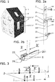
- zeigt eine perspektivische schematische Ansicht eines Gebäudes mit einer Gebäudehüllfläche, wobei die Fassadenfläche und die Dachfläche teilweise mit Photovoltaikmodulen gemäss hier vorgestelltem Verfahren geschuppt bedeckt sind.
- Figur 2a
- zeigt eine perspektivische Ansicht eines Halteelementes, während
- Figur 2b
- eine perspektivische Ansicht eines Bügelschuhs eines Halteelementes mit eingeschobenen PV-Modulen zeigt.
- Figur 3
- zeigt eine schematische Ansicht einer teilweise dreilagig geschuppten Bedeckung einer Gebäudehüllfläche mit PV-Modulen.
- Figur 4
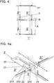
- zeigt eine schematische Ansicht einer teilweise vierlagig geschuppten Bedeckung einer Gebäudehüllfläche mit PV-Modulen.
- Figur 5a
- zeigt eine perspektivische Ansicht des Halteelements gemäss
Figur 2a , in welchem die Randbereiche von Photovoltaikmodulen teilweise überlappend und damit geschuppt angeordnet sind, während - Figur 5b
- eine Schnittansicht entlang der Linie A-A aus
Figur 5a zeigt und - Figur 5c
- eine weitere Schnittansicht von vier PV-Modulen mittels Halteelement befestigt an einer Fassade zeigt.
- Figur 6
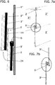
- zeigt eine detaillierte Schnittansicht geschuppt befestigter PV-Module, wobei die erste Lage, die der Fassade am nächsten liegt mit einem Schutzprofil ausgestattet ist.
- Figur 7a
- zeigt eine schematische Ansicht von PV-Modulen die geschuppt in Halteelementen hängend an einer Fassadenfläche angeordnet sind, während
- Figur 7b
- eine schematische Ansicht des Überlappungsbereiches zwischen einer ersten Lage und einer zweiten Lage von PV-Modulen zeigt.
- Als Gebäudehüllfläche 1 wird hier die Fläche eines Daches 1' oder einer Fassade 1" bezeichnet. Wie in
Figur 1 gezeigt, kann mit dem hier präsentierten Verfahren die Fassade 1" und das Dach 1' mit Photovoltaikmodulen 3, 3', 3", 3''' ausgestaltet werden, wobei die Photovoltaikmodule 3, 3', 3", 3"' in unterschiedlichen Lagen geschuppt auf der Gebäudehüllfläche 1 angeordnet werden. Dabei werden Photovoltaikmodule 3, 3', 3", 3''', die in Standardgrössen vorliegen flächig verteilt angeordnet. Die Photovoltaikmodule/ PV-Module 3 sind Teil einer Photovoltaikanlage, wobei die Photovoltaikmodule 3 mit Verbindungskabeln versehen sind, die auf der Rückseite verlaufen und an Zuleitungskabeln anschliessbar sind, welche in einen Wechselrichter geführt werden. - Die heute genutzten PV-Module 3, 3', 3", 3"' weisen eine Bypass-Diode auf, wodurch auch bei teilweiser Verschattung ein optimaler Stromertrag gewährleistet werden kann. Auch die durch die Schuppung oder Schuppendeckung entstehende teilweise Verschattung der PV-Module 3, 3', 3", 3''' wird durch die Bypass-Diode abgefangen, da auch teilbedeckte PV-Module 3, 3', 3", 3'" aktiv bleiben. Die geschuppte Bedeckung bzw. teilweise überlappende Bedeckung in mehreren PV-Modullagen muss ohne Verletzung der PV-Module 3, 3', 3", 3''' möglich sein. Mit dem hier vorgestellten Verfahren können handelsübliche PV-Module 3, 3', 3", 3"' fester Grössen ohne weiteren Zuschnitt oder Anbringung einer Lochung ausreichend stabil an einer Fassadenfläche 1" oder Dachfläche 1' montiert werden. Die absichtliche teilweise Verschattung von PV-Modulen 3, 3', 3", 3"' und damit eine Herabsetzung des Wirkungsgrades der PV-Anlage nimmt man in Kauf für ein erleichtertes kostengünstigeres Aufbauverfahren, wobei auch der ästhetische Gesamteindruck der geschuppten Fassadenfläche 1" verbessert wird. Mit den Doppelpfeilen in
Figur 1 sind Einschubrichtungen der verschiedenen PV-Module 3, 3', 3", 3''' angedeutet, was auch inFiguren 3 und5a näher erläutert wird. - Damit die Gebäudehüllfläche 1 mit Photovoltaikmodulen 3, 3', 3", 3'" bedeckt und die PV-Module 3, 3', 3", 3''' fixiert werden können, werden vorgängig Halteelemente 2, wie in
Figur 2a gezeigt in Form eines Befestigungsbügels 2 an der Dachfläche 1' oder der Fassadenfläche 1" befestigt. - Das Halteelement 2 weist in Richtung einer Halteelementlängsachse L einen Befestigungssteg 20 auf, an welchen sich eine abgewinkelte Wand 21 anschliesst. Befestigungssteg 20 und die Wand 21 sind zueinander etwa rechtwinklig verlaufend angeordnet. Von der Wand 21 geht der Befestigungsbügel 2 in Längsrichtung L in einen Haltesteg 22 mit einer Haltestegrückseite 220 und einer Haltestegvorderseite 221 über. Die Wand 21 und der Haltesteg 22 sind ebenfalls zueinander etwa rechtwinklig verlaufend gestaltet. Eine Rückseite 210 der Wand 21 weist in Richtung Haltesteg 22. Am von der Wand 21 abgewandten Ende des Haltestegs 22 ist ebenfalls abgewinkelt eine Auflagewand 23 angeordnet. Der Befestigungssteg 20 und der Haltesteg 22 sind etwa parallel zueinander verlaufend ausgestaltet. Durch die Abwinklung weisen die Wand 21 und die Auflagewand 23 vom Befestigungssteg 20 und Haltesteg 22 etwa senkrecht weg. Auf der Auflagewand 23 ist ein Bügelschuh 24 angeordnet, welcher von einer Bügelschuhstirnfläche 240 und Bügelschuhwänden 241 gebildet wird.
- Das Halteelement 2 weist mindestens ein Durchgangsloch 200, den Befestigungssteg 20 querend, auf und kann mit einem Befestigungsmittel 4 auf der Gebäudehüllfläche 1 fixiert werden. Bevorzugt wird das Halteelement 2 mit zwei Befestigungsmitteln 4, 4' entlang des Befestigungsstegs 20 an der Gebäudehüllfläche 1 befestigt. Durch das Unterlegen von Unterlagsscheiben unter den Haltebügel 20 beim Befestigungsmittel 4, 4' kann der Winkel zwischen Haltebügel 22 und Gebäudehüllfläche 1 je nach Schuppungsstärke angepasst werden.
- Mit der gestrichelten Linie ist eine senkrechte Fassadenfläche angedeutet. Bevorzugt ist das mindestens eine Befestigungsmittel 4, 4' als Schraube ausgeführt, es können aber auch Bolzen, Nägel oder Krampen, verwendet werden, welche mit einem Bolzensetzgerät bzw. einer Nagelpistole in die bestehende Fassade 1" getrieben werden. Die Halteelemente 2 können einfach mit den Befestigungsmitteln 4, 4' an einer Bestandsfassade befestigt werden, was vor allem bei Fassadenrenovationen bzw. -sanierungen einfach und schnell durchführbar ist. Die Befestigung des Halteelmentes 2 an der Fassadenfläche 1" erfolgt derart, dass der Befestigungssteg 20 etwa parallel zur Fassadenfläche 1" verlaufend befestigt ist. Entsprechend verläuft auch der Haltesteg 22 im montierten Zustand etwa parallel zur Fassadenfläche 1".
- Aus Stabilitätsgründen sollte das Halteelement 2 aus Metall gefertigt sein, wobei ein Stahlblech mit geeigneter Wandstärke bevorzugt ist. Im Wesentlichen besteht der Befestigungsbügel 2 aus einem Blech, an welchem der Bügelschuh 24 befestigt ist. Wahlweise kann der Befestigungsbügel 24 auch aus einem Aluminiumprofil gefertigt sein.
- Nach Befestigung der Halteelemente 2 können PV-Module 3, 3', 3", 3'" in unterschiedlichen Lagen, in unterschiedlichen Abständen zur Gebäudehüllfläche 1 bzw. zum Haltesteg 22 in Aufnahmen des Halteelementes 2 eingeschoben werden.
- Anstelle eines Bügelschuhs 24 mit einer Bügelschuhstirnfläche 240, welche das Herausschieben eines PV-Moduls 3" verhindert, kann auch ein Anschlag 5 am Bügelschuh 24 und/oder der Auflagewand 23 angeordnet sein. Hier ist der Anschlag 5 als Doppelkeil 5 ausgebildet, welcher zwischen den Bügelschuhwänden 241 angeordnet ist und ein Verschieben des PV-Moduls 3" verhindert. Der Doppelkeil 5 oder ein Einfachkeil 5 kann aus Kunststoff oder Gummi hergestellt sein und in den Bügelschuh 24 eingelegt oder darin verklebt gelagert sein. Eine weitere Möglichkeit eines Anschlages ist eine Bohrung in mindestens einer Bügelschuhwand 241 durch welche ein Bolzen gesteckt oder geschraubt wird. Der Anschlag 5 sorgt dafür, dass das PV-Modul 3" nicht über das Ende des Bügelschuhs 24 hinaus geschoben werden kann. Alternativ kann der Anschlag 5 an der Auflagewand 23 fixiert sein.
- Mit dem hier beschriebenen Verfahren können Gebäudehüllflächen dreilagig oder vierlagig geschuppt bedeckt werden. Die dreilagige Bedeckung wird in
Figur 3 gezeigt. - Ein PV-Modul 3' einer ersten Lage 3' wird in einer ersten Richtung mit ihrem Randbereich unter den Haltesteg 22 eingeschoben. Dabei kommt der Randbereich der ersten Lage 3' zwischen der Gebäudehüllfläche 1 und der Haltestegrückseite 220 zu liegen. Die erste Lage 3' ist immer direkt an der Fassaden- oder Dachfläche 1', 1" anliegend positioniert. Da der Befestigungsbügel 2 fixiert und ausreichend stabil ist, kann die erste Lage 3' nicht mehr von der Gebäudehüllfläche 1, senkrecht zur Gebäudehüllfläche 1, wegkippen.
- Dann kann ein PV-Modul einer zweiten Lage 3" in einer zweiten Richtung senkrecht zur ersten Richtung mit ihrem Randbereich auf der Auflagewand 23 liegend eingeschoben werden, wodurch es mit dem Halteelement 2 in Kontakt gebracht wird. Dieses PV-Modul der zweiten Lage 3" kann dabei teilweise auf der Haltestegvorderseite 221 aufliegen. Der Abschnitt zwischen Auflagewand 23 und Haltestegvorderseite 221 wirkt als Schiene, in welcher die zweite Lage 3" einschiebbar lagerbar ist.
- Nach der zweiten Lage 3" wird ein PV-Modul einer dritten Lage 3''' in einer dritten Richtung auf dem Bügelschuh 24 liegend bis zum Anschlag 5 bzw. der Bügelschuhwand 241 eingeschoben.
- Die zweite Lage 3" und dritte Lage 3"' ragen über die Haltestegvorderseite 221 und die Wand 21 des Halteelements 2 in Längsrichtung L des Halteelementes 2, wobei der Randbereich auf der Auflagewand 23 aufliegt. Die dritte Lage 3"' ist von der ersten und zweiten Lage 3', 3" und der Fassadenfläche 1 beabstandet im Halteelement 2 gelagert. Üblicherweise ist die dritte Lage 3''' in Richtung Befestigungssteg 20 zum Halteelement 2 verkippt gelagert. Bei dieser dreilagigen geschuppten Bedeckung bleiben in den Randbereichen Ecken frei, welche mit zugeschnittenen PV-Modulen bedeckt werden müssen.
- Darum bietet sich eine vierlagige geschuppte Bedeckung an, welche in
Figur 4 im Detail gezeigt ist. - In
Figur 4 sind PV-Module 3, 3', 3", 3"' mit gleicher Modulhöhe A gezeigt, welche mit dem im Folgenden beschriebenen Verfahren und der Halteelemente 2 an einer Fassadenfläche 1" eingeschoben geschuppt angebracht sind. - Durch die Schuppung weist jedes PV-Modul eine verdeckte Höhe B auf, sodass nicht die gesamte Fläche des PV-Moduls 3, 3', 3", 3''' zur Stromerzeugung beitragen kann. Dieser Fakt wird dadurch ausgeglichen, dass die Befestigung der PV-Module 3 erheblich vereinfacht ist, was zu Kostenersparnis führt. Alle PV-Module 3 werden durch die Halteelemente 2 und die Schwerkraft an der Gebäudehüllfläche 1 gehalten. Diese Art der Befestigung wiedersteht auch extremen Wetterbedingungen und kommt ohne einen Rahmenaufbau aus.
- Wie in
Figur 5a mit den Pfeilen gekennzeichnet, wird eine erste Lage 3' und eine Zwischenlage 3 in der ersten Richtung zwischen den Haltesteg 22 bzw. die Haltestegrückseite 220 und die Gebäudehüllfläche 1 eingeschoben. Die PV-Module der ersten Lage 3' und der Zwischenlage 3 werden dadurch in ihren Randbereichen vom Haltesteg 22 gegen ein Verkippen, weg von der Gebäudehüllfläche 1 gesichert. - Im nächsten Schritt wird die zweite Lage 3" in der zweiten Richtung senkrecht zur ersten Richtung, auf der Haltestegvorderseite 221 anliegend und mit ihrem Randberiech auf der Auflagewand 23 aufliegend eingebracht.
- Abschliessend wird die dritte Lage 3''' in der dritten Richtung mit ihrem Randbereich in den Bügelschuh 24 eingeschoben und damit mit dem Halteelement 2 in Kontakt gebracht.
- Der Randbereich der dritten Lage 3"' wird von den Bügelschuhwänden 241 umfasst. Die Bügelschuhstirnfläche 240 dient als Anschlag für das Einschieben in der dritten Richtung der dritten Lage 3"'. Die dritte Lage 3''' ist gegen die zweite Lage 3", das Halteelement 2 und die Fassadenfläche 1 verkippt.
- Im Randbereich der ersten bis vierten Lage 3, 3', 3", 3''' im Bereich der Auflagewand 23 bzw. des Bügelschuhs 24 des Halteelementes 2 überlappen die einzelnen PV-Module, wodurch eine geschuppte Bedeckung erreicht wird. Im Bereich des Halteelementes 2 sind die PV-Module in vier Lagen (I bis IV), beabstandet vom Halteelement 2 und der Fassadenfläche 1 angeordnet, was in
Figur 5b im Detail erkennbar ist. - Die erste Lage 3' ist direkt gegen die Fassadenfläche 1" verkippt in einer Ebene I gehalten. Die Zwischenlage 3 ist gegen die erste Lage 3' in Richtung Fassadenfläche 1" verkippt und wird mindestens teilweise vom Haltesteg 22 bzw. der Haltestegrückseite 220 gegen ein Entfernen von der Fassadenfläche 1" in einer Ebene II gehalten.
- Die Zwischenlage 3 und die erste Lage 3' sind damit teilweise zwischen Haltesteg 22 und Fassadenfläche 1" gehalten.
- Die zweite Lage 3" liegt teilweise angelehnt seitlich eingeschoben an den Haltesteg 22 angelehnt auf der Auflagewand 23 auf, in einer Ebene III.
- In einer Ebene IV liegt die dritte Lage 3''' angelehnt an die zweite Lage 3" seitlich in den Bügelschuh 24 eingeschoben und gehalten zwischen den Bügelschuhwänden 241. Alternativ können auch beide äusseren Lagen in einer Schiene zwischen Wand 221 und äusserer Bügelschuhwand 241 mittels Kunststoff- oder Gummiprofilen eingeklemmt werden.
- Im Bereich des Halteelementes 2, im gestrichelt umrahmten Abschnitt, sind insgesamt vier verschiedene Lagen 3, 3', 3", 3'" von PV-Modulen mit unterschiedlichen Abständen etwa senkrecht zur Gebäudehüllfläche 1 verbaut. Das Verfahren wird bis zur gewünschten Gesamtbedeckung der Fassadenfläche 1" bzw. Gebäudehüllfläche 1 durchgeführt. Die Überlappung ist in
Figur 5c in einer Seitenansicht im Bereich eines Halteelementes 2 nochmals gezeigt, wobei Randbereiche der ersten und zweiten Lage 3, 3' von Randbereichen der dritten und vierten Lagen 3", 3"' teilweise aufgrund der Schuppung verdeckt werden. - Um die Randbereiche vor allem der ersten Lage 3' der PV-Module zu schützen, ist ein Schutzprofil S, insbesondere aus einem elastischen Material wie Gummi bzw. einem Kunststoff hergestellt, eingesetzt. Das Schutzprofil S umfasst den Randbereich der ersten Lage 3' teilweise, sodass die erste Lage 3' weder direkt an der Gebäudehüllfläche 1" noch direkt an der Zwischenlage 3 anliegt, sofern eine Zwischenlage 3 verwendet wird.
- Es können auch weitere Schutzprofile S an den verschiedenen Lagen 3, 3", 3''' angeordnet werden, um ein direktes Aufliegen zu vermeiden. Durch die Anordnung von Schutzprofilen S kann eine nahezu wasserdichte Fassadenabdeckung bzw. Dachabdeckung erreicht werden.
- Durch die einfache Befestigung der Halteelemente 2 auf der Gebäudehüllfläche 1 können Unebenheiten der Gebäudehüllfläche 1 problemlos ausgeglichen werden. Ungenauigkeiten in der Unterkonstruktion können bei der Montage der Halteelemente 2 einfach aufgenommen werden. Durch das Überlappen der PV-Module 3, 3', 3", 3''' sind Unregelmässigkeiten der Gebäudehüllfläche 1 kaum sichtbar, weshalb sich diese Verfahren ausgezeichnet für Fassadenrenovationen eignet. Die geschuppte Anordnung der PV-Module 3 ersetzt die teuren Passstücke und Massanfertigungen von PV-Modulen 3. Die Halteelemente 2 können auch direkt auf eine bestehende Fassade geschraubt werden. Eine aufwändige Vermessung der Fassadenfläche vor der Bedeckung ist nicht nötig. PV-Module 3 in Standardgrössen können zur Bedeckung verwendet werden. Das Mass der Überlappung benachbarter Photovoltaikmodule 3, 3', 3", 3''' kann durch die Positionierung der Halteelemente 2 und die gewählte Einschiebeposition der Photovoltaikmodule 3, 3', 3", 3''' abgestimmt werden.
- Das Montageverfahren eignet sich sowohl für Fassaden 1" als auch für geneigte Dachflächen 1'. Dies bringt gestalterisch die Möglichkeit, Dach und Fassade in derselben Architektursprache zu gestalten.
- Um die PV-Module 3 verkabeln zu können, werden vor der Bedeckung der einzelnen Lagen Zuleitungskabel auf der Gebäudehüllfläche 1 verteilt, an welche die einzelnen PV-Module 3 mit ihren Verbindungskabeln angeschlossen werden, bevor die PV-Moduls 3 wie oben beschrieben in die Halteelemente 2 eingeschoben werden. Auch eine andere Verkabelung ist möglich, wobei verkabelte PV-Module 3 eingeschoben werden und die zugehörigen Verbindungskabel später kontaktiert und bis zum Wechselrichter geführt werden. Die Verbindungskabel und vorhandene Stecker und Buchsen sind hier nicht dargestellt.
- Um eine geschuppte Bedeckung einer Fassade 1" zu erzielen, können die Halteelemente 2 auch derart ausgestaltet sein, dass die PV-Module 3, 3', 3", 3''' mehrlagig einhängbar sind und teilweise geschuppt in ihren Überlappungsbereichen vertikal an der Fassade herabhängend montiert werden können. In den Randbereichen überlappen benachbarte PV-Module 3, 3', 3", 3''' ebenfalls. Gegen ein Lösen sind die PV-Module 3, 3', 3", 3'" durch die Halteelemente 2 gesichert, welche wieder fest an der Fassadenfläche 1" bzw. Dachfläche 1' fixiert sind. Damit die PV-Module 3, 3', 3", 3"' in den Überlappungsbereichen nicht aneinanderschlagen, sind Rückhalterungen 6 vorgesehen. Als Rückhalterungen 6 sind Klebe-, Magnet- oder Klettflächen bzw. Verbindungen mittels Klebstoff, Magneten oder Klettverschlüssen einsetzbar, welche auf einem der beiden benachbarten PV-Module oder auf beiden benachbarten PV-Modulen im Überlappungsbereich angebracht werden.
- Alle hier beschriebenen Montageverfahrenberuhen darauf, dass sich die Photovoltaik-Module 3, 3', 3", 3"' gegenseitig einklemmen und fixieren jedoch in der Vertikalen gegen oben verschiebbar bleiben und nur durch die Schwerkraft in ihrer vertikalen Position gehalten werden. Die Photovoltaik-Module 3, 3', 3", 3''' werden übereinander geschichtet, wobei die horizontalen Reihen sich direkt berühren und die vertikalen Reihen sich über die Halteelemente 2, 2' gegen ein Abkippen gegen aussen, also weg von der Fassadenfläche, zurückgehalten werden.
- Um eine ungewünschte horizontale Verschiebung zu verhindern, ist auf der Rückseite jedes PV-Moduls 3, 3', 3", 3"' ein Rippenelement aufgebracht, bevorzugt aufgeklebt. Das Rippenelement kann auf der Unterkonstruktion eingerastet sein bzw. an einem auf der Unterkonstruktion montiertem Gegenstück des Rippenelementes eingehakt bzw. eingerastet sein, wobei nur die horizontale Verschiebung verhindert ist. Die PV-Module 3, 3', 3", 3''' bleiben vertikal gegen oben ständig verschiebbar, weshalb ein Auswechseln eines beschädigten PV-Moduls 3, 3', 3", 3"' in der gesamten Fassade einfach von Hand mit einer Verschiebung nach oben erfolgen kann.
- Für gesteigerte Zerstörungssicherheit sind auf der Rückseite jedes PV-Moduls 3, 3', 3", 3"' im Bereich der Ecken, in welchen eine Überlagerung der PV-Module 3, 3', 3", 3''' erfolgt und damit eine direkte Berührung stattfindet, Gummi- oder Kunststoffelemente aufgeklebt. Um auch das ungewünschte horizontale Verrutschen von geschuppt verlegten PV-Modulen 3, 3', 3", 3"' relativ zueinander zu verhindern, kann das Rippenelement an einer der Ecken jedes PV-Moduls 3, 3', 3", 3''' auf der Rückseite aufgeklebt sein.
- Die beschriebenen Photovoltaikmodule 3, 3', 3", 3'" unterscheiden sich von einer Glastafel nicht nur durch die Mehrlagigkeit inklusive photovoltaische Lage, der elektrischen Verkabelung bzw. Anordnung elektrischer Bauteile, sondern auch durch die auf der Rückseite und/oder Frontseite jedes PV-Moduls 3, 3', 3", 3"' angebrachten Zusatzelement zum Schutz der PV-Module 3, 3', 3", 3'''.
-
- 1
- Gebäudehüllfläche
- 1'
- Dach
- 1"
- Fassade
- 2, 2'
- Halteelement / Befestigungsbügel
20 Befestigungssteg
200 Durchgangsloch
21 Wand
210 Rückseite erster Auflagewand
22 Haltesteg
220 Haltestegrückseite
221 Haltestegvorderseite
23 Auflagewand
24 Bügelschuh
240 Bügelschuhstirnfläche
241 Bügelschuhwand
L Halteelementlängsachse - 3
- PV-Modul
3 Zwischenlage
3' erste Lage
3" zweite Lage
3''' dritte Lage
A Modulhöhe
B verdeckte Höhe
S Schutzprofil (Gummi oder Kunststoff) - 4, 4'
- Befestigungsmittel
- 5
- Anschlag (Befestigungskeil, Doppelkeil, Bolzen)
- 6
- Rückhalterung
Claims (15)
- Verfahren zur Bedeckung von Gebäudehüllflächen (1) mit Photovoltaikmodulen (3, 3', 3", 3'"), wobei eine vertikal verschiebbare Halterung der Photovoltaikmodule (3, 3', 3", 3''') resultiert,
gekennzeichnet durch die Schritte:Befestigung einer Mehrzahl von Halteelementen (2) flächig verteilt auf der Gebäudehüllfläche (1),sukzessives Einschieben oder Einhängen der Randbereiche von mindestens drei Lagen von Photovoltaikmodulen (3, 3', 3", 3'") und Befestigung an den Halteelementen (2), wobei mindestens eine erste Lage (3') in Richtung einer Halteelementlängsachse (L) eingeschoben oder eingehängt wird, wobei die PV-Module (3, 3', 3", 3"') in ihren Randbereichen mittels Halteelement (2) in einer Richtung senkrecht zur Gebäudehüllfläche (1) beabstandet gehalten werden und eine Schuppung der benachbarten Photovoltaikmodule (3, 3', 3", 3"') mit mindestens teilweiser Überlappung aller angrenzenden mindestens drei Photovoltaikmodulflächen resultiert,wobei die Halteelemente (2) eine mindestens dreilagige Aufnahmemöglichkeit aufweisen, sodass nach Einschub oder Einhängen der ersten Lage (3') in einer ersten Richtung zwischen einen Haltesteg (22) des Haltelementes (2), die zweite Lage (3") in einer zweiten Richtung senkrecht zur ersten Richtung eingehängt oder mit ihrem Randbereich auf einer Auflagewand (23) des Halteelementes (2) liegend eingeschoben wird und anschliessend eine dritte Lage (3"') in einer dritten Richtung senkrecht zur ersten Richtung eingehängt oder auf einem Bügelschuh (24) des Halteelementes (2) liegend zwischen Bügelschuhwände (241) bis zu einem Anschlag (5) oder einer Bügelschuhwand (241) eingeschoben wird, wodurch eine mindestens annähernd senkrecht von der Gebäudehüllfläche (1) beabstandete geschuppte Lagerung der Photovoltaikmodule (3) resultiert. - Verfahren nach Anspruch 1, wobei die Halteelemente (2) eine mindestens vierlagige Aufnahmemöglichkeit aufweisen und eine Zwischenlage (3) zwischen den Haltesteg (22) bzw. die erste Lage (3') und die Gebäudehüllfläche (1) in Richtung der ersten Richtung eingehängt oder eingeschoben wird, wodurch die PV-Module (3, 3', 3", 3'") vierlagig geschuppt mit mindestens einem Halteelement (2) lösbar verbindbar sind.
- Verfahren nach Anspruch 2, wobei die erste Lage (3') oder die Zwischenlage (3) durch eine Haltestegrückseite (220) des Haltestegs (22) des Halteelementes (2) gegen abkippen von der Gebäudehüllfläche (1) gehalten ist und die zweite Lage (3") auf einer Auflagewand (23) des Halteelementes (2), gehalten durch eine Haltestegvorderseite (221) des Haltestegs (22), gelagert wird.
- Verfahren nach einem der vorhergehenden Ansprüche, wobei das Mass der Überlappung benachbarter Photovoltaikmodule (3, 3', 3", 3"') durch die Positionierung der Halteelemente (2) und die gewählte Einschiebeposition der Photovoltaikmodule (3, 3', 3", 3"') im Halteelement (2) abstimmbar ist.
- Verfahren nach einem der vorhergehenden Ansprüche, wobei die Verkabelung der PV-Module (3, 3', 3", 3"') zeitlich vor dem Einschieben der PV-Module (3, 3', 3", 3"') in die Halteelemente (2) erfolgt, indem vorgängig Zuleitungskabel auf der Gebäudehüllfläche (1) verteilt wurden, an welchen Verbindungskabel der PV-Module (3, 3', 3", 3"') befestigt werden bevor verkabelte PV-Module (3, 3', 3", 3"') in die Halteelemente (2) eingeschoben werden.
- Verfahren nach einem der vorhergehenden Ansprüche, wobei die Halteelemente (2) durch mindestens ein Befestigungsmittel (4) in Form einer Schraube, eines Bolzens oder eines Nagels an der Gebäudehüllfläche (1) fixiert werden.
- Verfahren nach einem der vorhergehenden Ansprüche, wobei die Randbereiche mindestens der PV-Module der ersten Lage (3') und/oder der Zwischenlage (3) vor der Verlegung mit einem Schutzprofil S, insbesondere aus einem elastischen Material versehen werden.
- Verfahren nach Anspruch 1, wobei die PV-Module (3, 3', 3", 3''') vertikal hängend montiert werden und in ihren Randbereichen dreifach oder vierfach geschuppt angeordnet werden und die überlappenden Randbereiche mittels Rückhalterung (6), insbesondere in Form eines Klettverschlusses, einer Magnetverbindung oder mittels Klebestoff verbunden werden, um ein hochklappen der PV-Module bei Windsog zu verhindern.
- Mittel zur Durchführung des Verfahrens zur Bedeckung von Gebäudehüllflächen (1) mit Photovoltaikmodulen (3) nach einem der vorhergehenden Ansprüche,
in Form eines Halteelements (2) mit mindestens dreilagiger Aufnahmemöglichkeit zur mindestens annähernd senkrecht von der Gebäudehüllfläche (1) beabstandeten Lagerung von Photovoltaikmodulen (3, 3', 3", 3'"), umfassend sich in Richtung einer Halteelementlängsachse (L) erstreckend einen Befestigungssteg (20), eine Wand (21), einen Haltesteg (22), eine Auflagewand (23) und einen Bügelschuh (24), wobei zwischen Wand (21) und Befestigungssteg (20) bzw. Haltesteg (22) ein Winkel von mindestens annähernd 90° ausgestaltet ist. - Mittel nach Anspruch 9, wobei das Halteelement (2) mindestens ein Durchgangsloch (200), den Befestigungssteg (20) querend, aufweist.
- Mittel nach einem der Ansprüche 9 oder 10, wobei ein Anschlag (5) an der Auflagewand (23) angeordnet ist.
- Mittel nach einem der Ansprüche 9 oder 10, wobei der Bügelschuh (24) zwei Bügelschuhwände (241) und einen Anschlag (5, 240) umfasst, wodurch die Einschubtiefe des PV-Moduls (3"') der äusseren Lage in einer Richtung begrenzt ist.
- Mittel nach einem der Ansprüche 11 oder 12, wobei der Anschlag (5) in Form einer Bügelschuhstirnfläche (240), eines Einfachkeils oder eines Doppelkeils (5) ausgestaltet ist.
- Mittel nach einem der Ansprüche 11 bis 13, wobei der Anschlag (5) aus Kunststoff oder Gummi hergestellt ist.
- Verwendung von Photovoltaikmodulen (3, 3', 3", 3"') zur Bedeckung von Gebäudehüllflächen (1),
dadurch gekennzeichnet, dass
eine Mehrzahl von Halteelementen (2) flächig auf der Gebäudehüllfläche (1) verteilt ist und
die Randbereiche von mindestens drei Lagen von Photovoltaikmodulen (3, 3', 3", 3'") eingeschoben oder eingehängt sind und an den Halteelementen (2) derart befestigt sind, dass mindestens eine erste Lage (3') in Richtung einer Halteelementlängsachse (L) gelagert ist, wobei die PV-Module (3, 3', 3", 3'") in ihren Randbereichen mittels Halteelement (2) in einer Richtung senkrecht zur Gebäudehüllfläche (1) beabstandet gehalten sind und eine Schuppung der benachbarten Photovoltaikmodule (3, 3', 3", 3'") mit mindestens teilweiser Überlappung aller angrenzenden mindestens drei Photovoltaikmodulflächen resultiert.
Applications Claiming Priority (1)
| Application Number | Priority Date | Filing Date | Title |
|---|---|---|---|
| CH00775/16A CH712594A1 (de) | 2016-06-16 | 2016-06-16 | Verfahren und Mittel zur Bedeckung von Gebäudehüllflächen mit Photovoltaikmodulen. |
Publications (2)
| Publication Number | Publication Date |
|---|---|
| EP3258595A1 true EP3258595A1 (de) | 2017-12-20 |
| EP3258595B1 EP3258595B1 (de) | 2024-10-23 |
Family
ID=56289261
Family Applications (1)
| Application Number | Title | Priority Date | Filing Date |
|---|---|---|---|
| EP17175614.1A Active EP3258595B1 (de) | 2016-06-16 | 2017-06-13 | Verfahren und mittel zur bedeckung von gebäudehüllflächen mit photovoltaikmodulen |
Country Status (2)
| Country | Link |
|---|---|
| EP (1) | EP3258595B1 (de) |
| CH (1) | CH712594A1 (de) |
Citations (3)
| Publication number | Priority date | Publication date | Assignee | Title |
|---|---|---|---|---|
| EP1136632A1 (de) * | 2000-03-20 | 2001-09-26 | Walter Meusburger | Halter für mindestens eine Glastafel einer Glasfasade |
| DE20304988U1 (de) * | 2003-03-26 | 2003-06-05 | Kock, Moritz, Dipl.-Ing., 14467 Potsdam | Glasbauelement und Glasverkleidung mit einer Anordnung von mehreren Glasbauelementen für ein Dach oder eine Fassade |
| DE202008012164U1 (de) * | 2008-09-13 | 2010-02-11 | Längle Glas GmbH | Glasfassade |
-
2016
- 2016-06-16 CH CH00775/16A patent/CH712594A1/de unknown
-
2017
- 2017-06-13 EP EP17175614.1A patent/EP3258595B1/de active Active
Patent Citations (3)
| Publication number | Priority date | Publication date | Assignee | Title |
|---|---|---|---|---|
| EP1136632A1 (de) * | 2000-03-20 | 2001-09-26 | Walter Meusburger | Halter für mindestens eine Glastafel einer Glasfasade |
| DE20304988U1 (de) * | 2003-03-26 | 2003-06-05 | Kock, Moritz, Dipl.-Ing., 14467 Potsdam | Glasbauelement und Glasverkleidung mit einer Anordnung von mehreren Glasbauelementen für ein Dach oder eine Fassade |
| DE202008012164U1 (de) * | 2008-09-13 | 2010-02-11 | Längle Glas GmbH | Glasfassade |
Also Published As
| Publication number | Publication date |
|---|---|
| CH712594A1 (de) | 2017-12-29 |
| EP3258595B1 (de) | 2024-10-23 |
Similar Documents
| Publication | Publication Date | Title |
|---|---|---|
| DE102013207827B4 (de) | Vorrichtung zum Befestigen von Solarmodulen und Dach | |
| EP2238393B1 (de) | Solarmodul-befestigungssystem | |
| EP2619382B1 (de) | Befestigungssystem für fassadenelemente, einlegeprofilschiene hierfür und montageverfahren | |
| EP1703037A1 (de) | Dach- oder Fassadenverkleidung | |
| DE202007016011U1 (de) | Haltevorrichtung für Solarmodule eines Solarfeldes | |
| EP2242112A2 (de) | Dacheindeckungssystem für Solarmodule | |
| DE102008051249A1 (de) | Photovoltaikanlage, Photovoltaikmodul und Verfahren zur Bestückung einer Photovoltaikanlage | |
| DE29503315U1 (de) | Befestigungsvorrichtung zur definierten Positionierung von Solarmodulen auf Flachdächern | |
| DE202008007662U1 (de) | Dachaufbau | |
| DE29809280U1 (de) | Halterung von Solarmodulen | |
| DE20120983U1 (de) | Modulhalter | |
| DE102008050529A1 (de) | Photovoltaikanlage, Photovoltaikmodul, Unterkonstruktion und Verfahren zur Bestückung einer Photovoltaikanlage | |
| DE112014004754T5 (de) | Befestigungsstruktur eines Dünnschicht-Photovoltaikzellenmoduls | |
| DE202009014816U1 (de) | Montagesystem für die Aufständerung von Solarmodulen | |
| DE19601095A1 (de) | Integrierte Photovoltaik Lärmschutzbauwerke | |
| DE2758067A1 (de) | Solarkollektoranlage | |
| DE102009051756A1 (de) | Montagesystem für die Aufständerung von Solarmodulen | |
| EP2400238A2 (de) | Aufständerung eines Solarmoduls | |
| DE102009056337B4 (de) | Montagesystem für Solarmodule sowie Sonnenenergieanlage mit dem Montagesystem | |
| DE212012000079U1 (de) | Fundationsanordnung | |
| EP3258595B1 (de) | Verfahren und mittel zur bedeckung von gebäudehüllflächen mit photovoltaikmodulen | |
| DE202012101572U1 (de) | Photovoltaikaufbau sowie Bausatz für den Photovoltaikaufbau | |
| DE29807808U1 (de) | Unterkonstruktion zur Halterung von Fassadenelementen | |
| DE102012102234A1 (de) | Solarmodul-System, Solarmodul-Baukasten und Solarmodul-Anordnung | |
| WO2010128081A2 (de) | Sonnenenergie nutzendes fassadenelement und eine das fassadenelement umfassende fassade sowie verfahren zur herstellung einer fassade |
Legal Events
| Date | Code | Title | Description |
|---|---|---|---|
| PUAI | Public reference made under article 153(3) epc to a published international application that has entered the european phase |
Free format text: ORIGINAL CODE: 0009012 |
|
| STAA | Information on the status of an ep patent application or granted ep patent |
Free format text: STATUS: THE APPLICATION HAS BEEN PUBLISHED |
|
| AK | Designated contracting states |
Kind code of ref document: A1 Designated state(s): AL AT BE BG CH CY CZ DE DK EE ES FI FR GB GR HR HU IE IS IT LI LT LU LV MC MK MT NL NO PL PT RO RS SE SI SK SM TR |
|
| AX | Request for extension of the european patent |
Extension state: BA ME |
|
| STAA | Information on the status of an ep patent application or granted ep patent |
Free format text: STATUS: REQUEST FOR EXAMINATION WAS MADE |
|
| 17P | Request for examination filed |
Effective date: 20180615 |
|
| RBV | Designated contracting states (corrected) |
Designated state(s): AL AT BE BG CH CY CZ DE DK EE ES FI FR GB GR HR HU IE IS IT LI LT LU LV MC MK MT NL NO PL PT RO RS SE SI SK SM TR |
|
| STAA | Information on the status of an ep patent application or granted ep patent |
Free format text: STATUS: EXAMINATION IS IN PROGRESS |
|
| 17Q | First examination report despatched |
Effective date: 20200313 |
|
| GRAP | Despatch of communication of intention to grant a patent |
Free format text: ORIGINAL CODE: EPIDOSNIGR1 |
|
| STAA | Information on the status of an ep patent application or granted ep patent |
Free format text: STATUS: GRANT OF PATENT IS INTENDED |
|
| RIC1 | Information provided on ipc code assigned before grant |
Ipc: E04D 3/365 20060101ALI20240507BHEP Ipc: E04F 13/08 20060101ALI20240507BHEP Ipc: H02S 20/22 20140101ALI20240507BHEP Ipc: H02S 20/26 20140101AFI20240507BHEP |
|
| INTG | Intention to grant announced |
Effective date: 20240605 |
|
| RAP3 | Party data changed (applicant data changed or rights of an application transferred) |
Owner name: SCHMID, RENE |
|
| RIN1 | Information on inventor provided before grant (corrected) |
Inventor name: SCHMID, RENE |
|
| GRAS | Grant fee paid |
Free format text: ORIGINAL CODE: EPIDOSNIGR3 |
|
| GRAA | (expected) grant |
Free format text: ORIGINAL CODE: 0009210 |
|
| STAA | Information on the status of an ep patent application or granted ep patent |
Free format text: STATUS: THE PATENT HAS BEEN GRANTED |
|
| AK | Designated contracting states |
Kind code of ref document: B1 Designated state(s): AL AT BE BG CH CY CZ DE DK EE ES FI FR GB GR HR HU IE IS IT LI LT LU LV MC MK MT NL NO PL PT RO RS SE SI SK SM TR |
|
| REG | Reference to a national code |
Ref country code: GB Ref legal event code: FG4D Free format text: NOT ENGLISH |
|
| REG | Reference to a national code |
Ref country code: CH Ref legal event code: EP |
|
| REG | Reference to a national code |
Ref country code: DE Ref legal event code: R096 Ref document number: 502017016505 Country of ref document: DE |
|
| REG | Reference to a national code |
Ref country code: IE Ref legal event code: FG4D Free format text: LANGUAGE OF EP DOCUMENT: GERMAN |
|
| REG | Reference to a national code |
Ref country code: LT Ref legal event code: MG9D |
|
| REG | Reference to a national code |
Ref country code: NL Ref legal event code: MP Effective date: 20241023 |
|
| PG25 | Lapsed in a contracting state [announced via postgrant information from national office to epo] |
Ref country code: NL Free format text: LAPSE BECAUSE OF FAILURE TO SUBMIT A TRANSLATION OF THE DESCRIPTION OR TO PAY THE FEE WITHIN THE PRESCRIBED TIME-LIMIT Effective date: 20241023 |
|
| PG25 | Lapsed in a contracting state [announced via postgrant information from national office to epo] |
Ref country code: NL Free format text: LAPSE BECAUSE OF FAILURE TO SUBMIT A TRANSLATION OF THE DESCRIPTION OR TO PAY THE FEE WITHIN THE PRESCRIBED TIME-LIMIT Effective date: 20241023 |
|
| PG25 | Lapsed in a contracting state [announced via postgrant information from national office to epo] |
Ref country code: HR Free format text: LAPSE BECAUSE OF FAILURE TO SUBMIT A TRANSLATION OF THE DESCRIPTION OR TO PAY THE FEE WITHIN THE PRESCRIBED TIME-LIMIT Effective date: 20241023 Ref country code: IS Free format text: LAPSE BECAUSE OF FAILURE TO SUBMIT A TRANSLATION OF THE DESCRIPTION OR TO PAY THE FEE WITHIN THE PRESCRIBED TIME-LIMIT Effective date: 20250223 Ref country code: PT Free format text: LAPSE BECAUSE OF FAILURE TO SUBMIT A TRANSLATION OF THE DESCRIPTION OR TO PAY THE FEE WITHIN THE PRESCRIBED TIME-LIMIT Effective date: 20250224 |
|
| PG25 | Lapsed in a contracting state [announced via postgrant information from national office to epo] |
Ref country code: FI Free format text: LAPSE BECAUSE OF FAILURE TO SUBMIT A TRANSLATION OF THE DESCRIPTION OR TO PAY THE FEE WITHIN THE PRESCRIBED TIME-LIMIT Effective date: 20241023 |
|
| PG25 | Lapsed in a contracting state [announced via postgrant information from national office to epo] |
Ref country code: BG Free format text: LAPSE BECAUSE OF FAILURE TO SUBMIT A TRANSLATION OF THE DESCRIPTION OR TO PAY THE FEE WITHIN THE PRESCRIBED TIME-LIMIT Effective date: 20241023 |
|
| PG25 | Lapsed in a contracting state [announced via postgrant information from national office to epo] |
Ref country code: ES Free format text: LAPSE BECAUSE OF FAILURE TO SUBMIT A TRANSLATION OF THE DESCRIPTION OR TO PAY THE FEE WITHIN THE PRESCRIBED TIME-LIMIT Effective date: 20241023 |
|
| PG25 | Lapsed in a contracting state [announced via postgrant information from national office to epo] |
Ref country code: NO Free format text: LAPSE BECAUSE OF FAILURE TO SUBMIT A TRANSLATION OF THE DESCRIPTION OR TO PAY THE FEE WITHIN THE PRESCRIBED TIME-LIMIT Effective date: 20250123 |
|
| PG25 | Lapsed in a contracting state [announced via postgrant information from national office to epo] |
Ref country code: LV Free format text: LAPSE BECAUSE OF FAILURE TO SUBMIT A TRANSLATION OF THE DESCRIPTION OR TO PAY THE FEE WITHIN THE PRESCRIBED TIME-LIMIT Effective date: 20241023 Ref country code: GR Free format text: LAPSE BECAUSE OF FAILURE TO SUBMIT A TRANSLATION OF THE DESCRIPTION OR TO PAY THE FEE WITHIN THE PRESCRIBED TIME-LIMIT Effective date: 20250124 |
|
| PG25 | Lapsed in a contracting state [announced via postgrant information from national office to epo] |
Ref country code: PL Free format text: LAPSE BECAUSE OF FAILURE TO SUBMIT A TRANSLATION OF THE DESCRIPTION OR TO PAY THE FEE WITHIN THE PRESCRIBED TIME-LIMIT Effective date: 20241023 |
|
| PG25 | Lapsed in a contracting state [announced via postgrant information from national office to epo] |
Ref country code: RS Free format text: LAPSE BECAUSE OF FAILURE TO SUBMIT A TRANSLATION OF THE DESCRIPTION OR TO PAY THE FEE WITHIN THE PRESCRIBED TIME-LIMIT Effective date: 20250123 |
|
| PG25 | Lapsed in a contracting state [announced via postgrant information from national office to epo] |
Ref country code: SM Free format text: LAPSE BECAUSE OF FAILURE TO SUBMIT A TRANSLATION OF THE DESCRIPTION OR TO PAY THE FEE WITHIN THE PRESCRIBED TIME-LIMIT Effective date: 20241023 |
|
| PGFP | Annual fee paid to national office [announced via postgrant information from national office to epo] |
Ref country code: DE Payment date: 20250618 Year of fee payment: 9 |
|
| PG25 | Lapsed in a contracting state [announced via postgrant information from national office to epo] |
Ref country code: DK Free format text: LAPSE BECAUSE OF FAILURE TO SUBMIT A TRANSLATION OF THE DESCRIPTION OR TO PAY THE FEE WITHIN THE PRESCRIBED TIME-LIMIT Effective date: 20241023 |
|
| PG25 | Lapsed in a contracting state [announced via postgrant information from national office to epo] |
Ref country code: EE Free format text: LAPSE BECAUSE OF FAILURE TO SUBMIT A TRANSLATION OF THE DESCRIPTION OR TO PAY THE FEE WITHIN THE PRESCRIBED TIME-LIMIT Effective date: 20241023 |
|
| PG25 | Lapsed in a contracting state [announced via postgrant information from national office to epo] |
Ref country code: RO Free format text: LAPSE BECAUSE OF FAILURE TO SUBMIT A TRANSLATION OF THE DESCRIPTION OR TO PAY THE FEE WITHIN THE PRESCRIBED TIME-LIMIT Effective date: 20241023 |
|
| PGFP | Annual fee paid to national office [announced via postgrant information from national office to epo] |
Ref country code: AT Payment date: 20250616 Year of fee payment: 9 |
|
| REG | Reference to a national code |
Ref country code: DE Ref legal event code: R097 Ref document number: 502017016505 Country of ref document: DE |
|
| PG25 | Lapsed in a contracting state [announced via postgrant information from national office to epo] |
Ref country code: SK Free format text: LAPSE BECAUSE OF FAILURE TO SUBMIT A TRANSLATION OF THE DESCRIPTION OR TO PAY THE FEE WITHIN THE PRESCRIBED TIME-LIMIT Effective date: 20241023 |
|
| PG25 | Lapsed in a contracting state [announced via postgrant information from national office to epo] |
Ref country code: CZ Free format text: LAPSE BECAUSE OF FAILURE TO SUBMIT A TRANSLATION OF THE DESCRIPTION OR TO PAY THE FEE WITHIN THE PRESCRIBED TIME-LIMIT Effective date: 20241023 |
|
| PG25 | Lapsed in a contracting state [announced via postgrant information from national office to epo] |
Ref country code: IT Free format text: LAPSE BECAUSE OF FAILURE TO SUBMIT A TRANSLATION OF THE DESCRIPTION OR TO PAY THE FEE WITHIN THE PRESCRIBED TIME-LIMIT Effective date: 20241023 |
|
| PLBE | No opposition filed within time limit |
Free format text: ORIGINAL CODE: 0009261 |
|
| STAA | Information on the status of an ep patent application or granted ep patent |
Free format text: STATUS: NO OPPOSITION FILED WITHIN TIME LIMIT |
|
| PG25 | Lapsed in a contracting state [announced via postgrant information from national office to epo] |
Ref country code: SE Free format text: LAPSE BECAUSE OF FAILURE TO SUBMIT A TRANSLATION OF THE DESCRIPTION OR TO PAY THE FEE WITHIN THE PRESCRIBED TIME-LIMIT Effective date: 20241023 |
|
| 26N | No opposition filed |
Effective date: 20250724 |
|
| PGFP | Annual fee paid to national office [announced via postgrant information from national office to epo] |
Ref country code: CH Payment date: 20250701 Year of fee payment: 9 |
|
| PG25 | Lapsed in a contracting state [announced via postgrant information from national office to epo] |
Ref country code: MC Free format text: LAPSE BECAUSE OF FAILURE TO SUBMIT A TRANSLATION OF THE DESCRIPTION OR TO PAY THE FEE WITHIN THE PRESCRIBED TIME-LIMIT Effective date: 20241023 |
|
| PG25 | Lapsed in a contracting state [announced via postgrant information from national office to epo] |
Ref country code: LU Free format text: LAPSE BECAUSE OF NON-PAYMENT OF DUE FEES Effective date: 20250613 |
|
| GBPC | Gb: european patent ceased through non-payment of renewal fee |
Effective date: 20250613 |
|
| REG | Reference to a national code |
Ref country code: BE Ref legal event code: MM Effective date: 20250630 |
|
| PG25 | Lapsed in a contracting state [announced via postgrant information from national office to epo] |
Ref country code: GB Free format text: LAPSE BECAUSE OF NON-PAYMENT OF DUE FEES Effective date: 20250613 |
|
| PG25 | Lapsed in a contracting state [announced via postgrant information from national office to epo] |
Ref country code: IE Free format text: LAPSE BECAUSE OF NON-PAYMENT OF DUE FEES Effective date: 20250613 |
|
| PG25 | Lapsed in a contracting state [announced via postgrant information from national office to epo] |
Ref country code: BE Free format text: LAPSE BECAUSE OF NON-PAYMENT OF DUE FEES Effective date: 20250630 |
|
| PG25 | Lapsed in a contracting state [announced via postgrant information from national office to epo] |
Ref country code: FR Free format text: LAPSE BECAUSE OF NON-PAYMENT OF DUE FEES Effective date: 20250630 |