EP3258595A1 - Procédé et moyen de recouvrement de surfaces d'enveloppe de bâtiment au moyen de panneaux photovoltaïques - Google Patents
Procédé et moyen de recouvrement de surfaces d'enveloppe de bâtiment au moyen de panneaux photovoltaïques Download PDFInfo
- Publication number
- EP3258595A1 EP3258595A1 EP17175614.1A EP17175614A EP3258595A1 EP 3258595 A1 EP3258595 A1 EP 3258595A1 EP 17175614 A EP17175614 A EP 17175614A EP 3258595 A1 EP3258595 A1 EP 3258595A1
- Authority
- EP
- European Patent Office
- Prior art keywords
- modules
- holding
- layer
- building envelope
- photovoltaic modules
- Prior art date
- Legal status (The legal status is an assumption and is not a legal conclusion. Google has not performed a legal analysis and makes no representation as to the accuracy of the status listed.)
- Granted
Links
Images

Classifications
-
- F—MECHANICAL ENGINEERING; LIGHTING; HEATING; WEAPONS; BLASTING
- F24—HEATING; RANGES; VENTILATING
- F24S—SOLAR HEAT COLLECTORS; SOLAR HEAT SYSTEMS
- F24S25/00—Arrangement of stationary mountings or supports for solar heat collector modules
- F24S25/30—Arrangement of stationary mountings or supports for solar heat collector modules using elongate rigid mounting elements extending substantially along the supporting surface, e.g. for covering buildings with solar heat collectors
-
- H—ELECTRICITY
- H02—GENERATION; CONVERSION OR DISTRIBUTION OF ELECTRIC POWER
- H02S—GENERATION OF ELECTRIC POWER BY CONVERSION OF INFRARED RADIATION, VISIBLE LIGHT OR ULTRAVIOLET LIGHT, e.g. USING PHOTOVOLTAIC [PV] MODULES
- H02S20/00—Supporting structures for PV modules
- H02S20/20—Supporting structures directly fixed to an immovable object
- H02S20/22—Supporting structures directly fixed to an immovable object specially adapted for buildings
- H02S20/26—Building materials integrated with PV modules, e.g. façade elements
-
- F—MECHANICAL ENGINEERING; LIGHTING; HEATING; WEAPONS; BLASTING
- F24—HEATING; RANGES; VENTILATING
- F24S—SOLAR HEAT COLLECTORS; SOLAR HEAT SYSTEMS
- F24S20/00—Solar heat collectors specially adapted for particular uses or environments
- F24S20/60—Solar heat collectors integrated in fixed constructions, e.g. in buildings
- F24S20/66—Solar heat collectors integrated in fixed constructions, e.g. in buildings in the form of facade constructions, e.g. wall constructions
-
- F—MECHANICAL ENGINEERING; LIGHTING; HEATING; WEAPONS; BLASTING
- F24—HEATING; RANGES; VENTILATING
- F24S—SOLAR HEAT COLLECTORS; SOLAR HEAT SYSTEMS
- F24S20/00—Solar heat collectors specially adapted for particular uses or environments
- F24S20/60—Solar heat collectors integrated in fixed constructions, e.g. in buildings
- F24S20/69—Solar heat collectors integrated in fixed constructions, e.g. in buildings in the form of shingles or tiles
-
- F—MECHANICAL ENGINEERING; LIGHTING; HEATING; WEAPONS; BLASTING
- F24—HEATING; RANGES; VENTILATING
- F24S—SOLAR HEAT COLLECTORS; SOLAR HEAT SYSTEMS
- F24S25/00—Arrangement of stationary mountings or supports for solar heat collector modules
- F24S25/60—Fixation means, e.g. fasteners, specially adapted for supporting solar heat collector modules
- F24S25/61—Fixation means, e.g. fasteners, specially adapted for supporting solar heat collector modules for fixing to the ground or to building structures
- F24S25/613—Fixation means, e.g. fasteners, specially adapted for supporting solar heat collector modules for fixing to the ground or to building structures in the form of bent strips or assemblies of strips; Hook-like connectors; Connectors to be mounted between building-covering elements
-
- H—ELECTRICITY
- H02—GENERATION; CONVERSION OR DISTRIBUTION OF ELECTRIC POWER
- H02S—GENERATION OF ELECTRIC POWER BY CONVERSION OF INFRARED RADIATION, VISIBLE LIGHT OR ULTRAVIOLET LIGHT, e.g. USING PHOTOVOLTAIC [PV] MODULES
- H02S20/00—Supporting structures for PV modules
- H02S20/20—Supporting structures directly fixed to an immovable object
- H02S20/22—Supporting structures directly fixed to an immovable object specially adapted for buildings
-
- E—FIXED CONSTRUCTIONS
- E04—BUILDING
- E04D—ROOF COVERINGS; SKY-LIGHTS; GUTTERS; ROOF-WORKING TOOLS
- E04D1/00—Roof covering by making use of tiles, slates, shingles, or other small roofing elements
- E04D1/34—Fastenings for attaching roof-covering elements to the supporting elements
- E04D2001/3408—Fastenings for attaching roof-covering elements to the supporting elements characterised by the fastener type or material
- E04D2001/3414—Metal strips or sheet metal
-
- E—FIXED CONSTRUCTIONS
- E04—BUILDING
- E04D—ROOF COVERINGS; SKY-LIGHTS; GUTTERS; ROOF-WORKING TOOLS
- E04D1/00—Roof covering by making use of tiles, slates, shingles, or other small roofing elements
- E04D1/34—Fastenings for attaching roof-covering elements to the supporting elements
- E04D2001/3452—Fastenings for attaching roof-covering elements to the supporting elements characterised by the location of the fastening means
- E04D2001/3458—Fastenings for attaching roof-covering elements to the supporting elements characterised by the location of the fastening means on the upper or lower transverse edges of the roof covering elements
-
- E—FIXED CONSTRUCTIONS
- E04—BUILDING
- E04F—FINISHING WORK ON BUILDINGS, e.g. STAIRS, FLOORS
- E04F13/00—Coverings or linings, e.g. for walls or ceilings
- E04F13/07—Coverings or linings, e.g. for walls or ceilings composed of covering or lining elements; Sub-structures therefor; Fastening means therefor
- E04F13/08—Coverings or linings, e.g. for walls or ceilings composed of covering or lining elements; Sub-structures therefor; Fastening means therefor composed of a plurality of similar covering or lining elements
- E04F13/0801—Separate fastening elements
- E04F13/0832—Separate fastening elements without load-supporting elongated furring elements between wall and covering elements
- E04F13/0833—Separate fastening elements without load-supporting elongated furring elements between wall and covering elements not adjustable
- E04F13/0841—Separate fastening elements without load-supporting elongated furring elements between wall and covering elements not adjustable the fastening elements engaging the outer surface of the covering elements, not extending through the covering
-
- E—FIXED CONSTRUCTIONS
- E04—BUILDING
- E04F—FINISHING WORK ON BUILDINGS, e.g. STAIRS, FLOORS
- E04F13/00—Coverings or linings, e.g. for walls or ceilings
- E04F13/07—Coverings or linings, e.g. for walls or ceilings composed of covering or lining elements; Sub-structures therefor; Fastening means therefor
- E04F13/08—Coverings or linings, e.g. for walls or ceilings composed of covering or lining elements; Sub-structures therefor; Fastening means therefor composed of a plurality of similar covering or lining elements
- E04F13/0864—Coverings or linings, e.g. for walls or ceilings composed of covering or lining elements; Sub-structures therefor; Fastening means therefor composed of a plurality of similar covering or lining elements composed of superposed elements which overlap each other and of which the flat outer surface includes an acute angle with the surface to cover
-
- F—MECHANICAL ENGINEERING; LIGHTING; HEATING; WEAPONS; BLASTING
- F24—HEATING; RANGES; VENTILATING
- F24S—SOLAR HEAT COLLECTORS; SOLAR HEAT SYSTEMS
- F24S20/00—Solar heat collectors specially adapted for particular uses or environments
- F24S2020/10—Solar modules layout; Modular arrangements
- F24S2020/13—Overlaying arrangements similar to roof tiles
-
- F—MECHANICAL ENGINEERING; LIGHTING; HEATING; WEAPONS; BLASTING
- F24—HEATING; RANGES; VENTILATING
- F24S—SOLAR HEAT COLLECTORS; SOLAR HEAT SYSTEMS
- F24S25/00—Arrangement of stationary mountings or supports for solar heat collector modules
- F24S25/60—Fixation means, e.g. fasteners, specially adapted for supporting solar heat collector modules
- F24S2025/6002—Fixation means, e.g. fasteners, specially adapted for supporting solar heat collector modules by using hooks
-
- Y—GENERAL TAGGING OF NEW TECHNOLOGICAL DEVELOPMENTS; GENERAL TAGGING OF CROSS-SECTIONAL TECHNOLOGIES SPANNING OVER SEVERAL SECTIONS OF THE IPC; TECHNICAL SUBJECTS COVERED BY FORMER USPC CROSS-REFERENCE ART COLLECTIONS [XRACs] AND DIGESTS
- Y02—TECHNOLOGIES OR APPLICATIONS FOR MITIGATION OR ADAPTATION AGAINST CLIMATE CHANGE
- Y02B—CLIMATE CHANGE MITIGATION TECHNOLOGIES RELATED TO BUILDINGS, e.g. HOUSING, HOUSE APPLIANCES OR RELATED END-USER APPLICATIONS
- Y02B10/00—Integration of renewable energy sources in buildings
- Y02B10/10—Photovoltaic [PV]
-
- Y—GENERAL TAGGING OF NEW TECHNOLOGICAL DEVELOPMENTS; GENERAL TAGGING OF CROSS-SECTIONAL TECHNOLOGIES SPANNING OVER SEVERAL SECTIONS OF THE IPC; TECHNICAL SUBJECTS COVERED BY FORMER USPC CROSS-REFERENCE ART COLLECTIONS [XRACs] AND DIGESTS
- Y02—TECHNOLOGIES OR APPLICATIONS FOR MITIGATION OR ADAPTATION AGAINST CLIMATE CHANGE
- Y02B—CLIMATE CHANGE MITIGATION TECHNOLOGIES RELATED TO BUILDINGS, e.g. HOUSING, HOUSE APPLIANCES OR RELATED END-USER APPLICATIONS
- Y02B10/00—Integration of renewable energy sources in buildings
- Y02B10/20—Solar thermal
-
- Y—GENERAL TAGGING OF NEW TECHNOLOGICAL DEVELOPMENTS; GENERAL TAGGING OF CROSS-SECTIONAL TECHNOLOGIES SPANNING OVER SEVERAL SECTIONS OF THE IPC; TECHNICAL SUBJECTS COVERED BY FORMER USPC CROSS-REFERENCE ART COLLECTIONS [XRACs] AND DIGESTS
- Y02—TECHNOLOGIES OR APPLICATIONS FOR MITIGATION OR ADAPTATION AGAINST CLIMATE CHANGE
- Y02E—REDUCTION OF GREENHOUSE GAS [GHG] EMISSIONS, RELATED TO ENERGY GENERATION, TRANSMISSION OR DISTRIBUTION
- Y02E10/00—Energy generation through renewable energy sources
- Y02E10/40—Solar thermal energy, e.g. solar towers
- Y02E10/47—Mountings or tracking
-
- Y—GENERAL TAGGING OF NEW TECHNOLOGICAL DEVELOPMENTS; GENERAL TAGGING OF CROSS-SECTIONAL TECHNOLOGIES SPANNING OVER SEVERAL SECTIONS OF THE IPC; TECHNICAL SUBJECTS COVERED BY FORMER USPC CROSS-REFERENCE ART COLLECTIONS [XRACs] AND DIGESTS
- Y02—TECHNOLOGIES OR APPLICATIONS FOR MITIGATION OR ADAPTATION AGAINST CLIMATE CHANGE
- Y02E—REDUCTION OF GREENHOUSE GAS [GHG] EMISSIONS, RELATED TO ENERGY GENERATION, TRANSMISSION OR DISTRIBUTION
- Y02E10/00—Energy generation through renewable energy sources
- Y02E10/50—Photovoltaic [PV] energy
Definitions
- the present invention describes a method for covering building envelope surfaces with photovoltaic modules and means for carrying out the method, as well as the use of photovoltaic modules for covering building envelope surfaces.
- PV systems include a number of photovoltaic modules (PV modules) which are now mounted on as many open spaces as possible in order to advance the power supply with renewable energy in large steps.
- the covering of building envelope surfaces, in particular of building-integrated systems in facade surfaces is today associated with high costs, since a great deal of effort for the accurate planning and calibration of the building and a dimensionally accurate prefabrication of the photovoltaic modules with various special sizes is necessary.
- the usual systems usually include one or more support frames, which must be adapted to the building envelope exactly, so in turn adapted to the building envelope PV modules can be fitted to the millimeter between window and projections in the facade surface and screwed there in the support frame.
- a support frame does not forgive any inaccuracies in dimension, otherwise the PV modules can not be attached. With such support frame are Unevenness and working tolerances of the building envelope are difficult to compensate.
- PV modules with different module sizes are required for different storey heights.
- a complicated assembly is the result, in which it can easily lead to errors. If the building does not have the exact dimensions you want, the structure of the PV system will be stagnant. In order to achieve a maximum power yield, care is taken to make the entire surface of the PV modules accessible to solar radiation.
- the present invention has for its object to provide a simplified method for covering building envelope surfaces with photovoltaic modules, wherein the cost of the prefabrication and final assembly of the photovoltaic modules are significantly reduced.
- a support member for carrying out the method is claimed in claim 6 and following and provides a means for achieving a simplified and accelerated coverage of the building envelope.
- the method according to the invention eliminates the need for a costly measurement technique. It can be scaled on the entire building envelope PV modules with the same dimensions to be ordered. A variable sliding over of the PV modules allows almost full occupancy of the building envelope to be occupied, whereby only occasionally cost-intensive special sizes of the PV modules are required.
- the fixation against a horizontal displacement of the photovoltaic modules by attachment to a single mounting point but so that the vertical displacement is maintained.
- the PV module is not clamped to a support point, resulting in a "loose” bracket.
- the holding position on the quadrangular photovoltaic modules is in each case at least two superimposed corners at the very edge of the photovoltaic module.
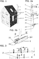
- the building envelope 1 is here the area of a roof 1 'or a facade 1 " FIG. 1 shown, with the method presented here, the facade 1 "and the roof 1 'with photovoltaic modules 3, 3', 3", 3 ''are configured, wherein the photovoltaic modules 3, 3', 3 ", 3"'in different Layers scaled on the building envelope 1 can be arranged.
- photovoltaic modules 3, 3 ', 3 ", 3''' which are present in standard sizes, are distributed in a planar manner.
- the photovoltaic modules / PV modules 3 are part of a photovoltaic system, wherein the photovoltaic modules 3 are provided with connecting cables running on the rear side and can be connected to supply cables, which are fed into an inverter.
- the PV modules used today 3, 3 ', 3 ", 3”' have a bypass diode, whereby an optimal power yield can be ensured even with partial shading.
- the partial shading of the PV modules 3, 3 ', 3 ", 3'” produced by the scaling or scaling is also intercepted by the bypass diode, since also partially covered PV modules 3, 3 ', 3 ", 3'.
- the scaly covering or partially overlapping covering in several PV module positions must be possible without infringing the PV modules 3, 3 ', 3 ", 3'''.
- the building envelope 1 can be covered with photovoltaic modules 3, 3 ', 3 ", 3'” and the PV modules 3, 3 ', 3 ", 3''' can be fixed, retaining elements 2, as in FIG FIG. 2a shown in the form of a mounting bracket 2 on the roof surface 1 'or the facade surface 1 "attached.
- the holding element 2 has in the direction of a holding element longitudinal axis L a fastening web 20, to which an angled wall 21 connects. Fixing web 20 and the wall 21 are arranged extending approximately at right angles to each other. From the wall 21 of the mounting bracket 2 is in the longitudinal direction L in a holding web 22 with a holding back side 220 and a holding web front side 221 over. The wall 21 and the retaining web 22 are also designed to each other approximately at right angles. A rear side 210 of the wall 21 points in the direction of retaining web 22. At the end of the retaining web 22 facing away from the wall 21, an abutment wall 23 is also angled. The fastening web 20 and the retaining web 22 are designed to extend approximately parallel to one another.
- a hanger shoe 24 is arranged, which is formed by a hanger shoe face 240 and hanger shoe walls 241.
- the retaining element 2 has at least one through hole 200, the fastening web 20 crossing, and can be fixed with a fastening means 4 on the building envelope 1.
- the holding element 2 is fastened with two fastening means 4, 4 'along the fastening web 20 to the building envelope surface 1.
- the at least one fastening means 4, 4 ' is designed as a screw, but it is also possible to use bolts, nails or staples, which are driven into the existing facade 1 "with a bolt setting tool or a nail gun
- the attachment of the Garelmentes 2 on the facade surface 1 " is carried out such that the fastening web 20 approximately parallel to the facade surface 1". Accordingly, the retaining web 22 extends in the assembled state approximately parallel to the facade surface 1 ".
- the holding element 2 should be made of metal, with a steel sheet with a suitable wall thickness being preferred.
- the mounting bracket 2 consists of a metal sheet to which the ironing shoe 24 is attached.
- the mounting bracket 24 may be made of an aluminum profile.
- PV modules 3, 3 ', 3 ", 3'” can be inserted in different positions, at different distances from the building envelope surface 1 or the holding web 22 in receptacles of the holding element 2.
- a stop 5 can also be arranged on the hanger shoe 24 and / or the support wall 23.
- the stopper 5 is designed as a double wedge 5, which is located between the two Bar shoe walls 241 is arranged and a displacement of the PV module 3 "prevented.
- the double wedge 5 or a single wedge 5 can be made of plastic or rubber and in the ironing shoe 24 inserted or stored glued therein.
- Another possibility of a stop is a hole in at least one ironing shoe wall 241 through which a bolt is inserted or screwed. The stop 5 ensures that the PV module 3 "can not be pushed beyond the end of the hanger shoe 24.
- the stop 5 can be fixed to the support wall 23.
- building envelope surfaces can be covered in three layers or four layers.
- the three-ply covering will be in FIG. 3 shown.
- a PV module 3 'of a first layer 3' is inserted in a first direction with its edge region under the retaining web 22.
- the edge region of the first layer 3 ' comes to lie between the building envelope surface 1 and the holding back side 220.
- the first layer 3 ' is always positioned directly adjacent to the façade or roof surface 1', 1 "Since the fastening clip 2 is fixed and sufficiently stable, the first layer 3 'can no longer be separated from the building envelope surface 1, perpendicular to the building envelope surface 1, tilt away.
- a PV module of a second layer 3 "in a second direction perpendicular to the first direction can be inserted lying with its edge region on the support wall 23, whereby it is brought into contact with the holding element 2.
- This PV module of the second layer 3" can partially rest on the holding web front 221.
- the section between support wall 23 and retaining web front side 221 acts as a rail, in which the second layer 3 "can be inserted in an insertable manner.
- a PV module of a third layer 3 '" is pushed in a third direction on the ironing shoe 24 as far as the stop 5 or the ironing shoe wall 241.
- corners remain free in the border areas, which must be covered with cut-to-size PV modules.
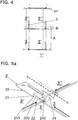
- PV modules 3, 3 ', 3 ", 3"' shown with the same module height A, which are mounted maruppt with the method described below and the holding elements 2 on a facade surface 1 ".
- each PV module has a hidden height B, so that the entire surface of the PV module 3, 3 ', 3 ", 3' '' can not contribute to the generation of electricity PV Modules 3 is considerably simplified, which leads to cost savings.
- All PV modules 3 are held by the holding elements 2 and the gravity of the building envelope 1. This type of attachment can withstand even extreme weather conditions and does not require a frame structure.
- the PV modules of the first layer 3 'and the intermediate layer 3 are thereby secured in their edge regions by the retaining web 22 against tilting, away from the building envelope 1.
- the second layer 3 "in the second direction perpendicular to the first direction, on the support web front side 221 fitting and introduced with its Randberiech resting on the support wall 23.
- the third layer 3 '' 'in the third direction is inserted with its edge region in the ironing shoe 24 and thus brought into contact with the holding element 2.
- the edge region of the third layer 3 "' is encompassed by the hanger shoe walls 241.
- the ironing shoe end surface 240 serves as a stop for insertion in the third direction of the third layer 3"'.
- the third layer 3 '' ' is tilted against the second layer 3 ", the holding element 2 and the facade surface 1.
- the PV modules are arranged in four layers (I to IV), spaced from the holding element 2 and the facade surface 1, which in FIG. 5b can be seen in detail.
- the first layer 3 ' is tilted directly against the facade surface 1 "and held in a plane I.
- the intermediate layer 3 is tilted against the first layer 3' in the direction of the facade surface 1" and is at least partly removed from the retaining web 22 or the retaining back 220 against removal held by the facade surface 1 "in a plane II.
- the intermediate layer 3 and the first layer 3 ' are thus partially held between retaining web 22 and facade surface 1 ".
- the second layer 3 "is partially ajar inserted laterally on the retaining web 22 ajar against the support wall 23, in a plane III.
- the third layer 3 '' ' is based on the second layer 3 "laterally inserted into the hanger shoe 24 and held between the hanger shoe walls 241.
- both outer layers in a rail between the wall 221 and outer hanger shoe wall 241 by means of plastic - or rubber profiles are trapped.
- FIG. 5c shown again in a side view in the region of a holding element 2, wherein edge regions of the first and second layer 3, 3 'of edge regions of the third and fourth layers 3 ", 3"' are partially obscured due to the scaling.
- a protective profile S in particular made of an elastic material such as rubber or a plastic used.
- the protective profile S comprises the edge region of the first layer 3 'partially, so that the first layer 3' neither directly on the building envelope surface 1 "still rests directly on the intermediate layer 3, if an intermediate layer 3 is used.
- the holding elements 2 can also be screwed directly onto an existing façade.A complex measurement of the façade surface before the covering is not necessary.
- PV modules 3 in standard sizes can be used for covering. The measure of the overlap of adjacent photovoltaic modules 3 , 3 ', 3 ", 3' '' can be tuned by the positioning of the holding elements 2 and the selected insertion position of the photovoltaic modules 3, 3 ', 3", 3' ''.
- the mounting method is suitable for facades 1 "as well as for inclined roof surfaces 1. This gives the design the opportunity to design the roof and façade in the same architectural language.
- supply cables are distributed on the building envelope 1 to cover the individual layers, to which the individual PV modules 3 are connected with their connecting cables before the PV module 3 as described above in the holding elements 2 are inserted. Also another wiring is possible, with wired PV modules 3 are inserted and the associated connecting cables are contacted later and fed to the inverter.
- the connection cable and existing plugs and sockets are not shown here.
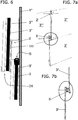
- the holding elements 2 can also be configured in such a way that the PV modules 3, 3 ', 3", 3' '' can be suspended in several layers and partially scaly in their overlapping areas vertically on the facade can be mounted hanging down. Adjacent PV modules 3, 3 ', 3 ", 3' '' also overlap in the edge areas, and the PV modules 3, 3 ', 3", 3' "are secured against loosening by the retaining elements 2, which are fixed again are fixed to the facade surface 1 "or roof surface 1 '. So that the PV modules 3, 3 ', 3 ", 3”' do not hit one another in the overlapping areas, retention devices 6 are provided. Adhesive, magnetic or Velcro surfaces or connections by means of adhesive, magnets or Velcro fasteners can be used as restraints 6, which are applied to one of the two adjacent PV modules or to both adjacent PV modules in the overlapping area.
- All assembly methods described here are based on the fact that the photovoltaic modules 3, 3 ', 3 ", 3"' clamp each other and fix but remain vertically displaceable upwards and are held only in their vertical position by gravity.
- the photovoltaic modules 3, 3 ', 3 ", 3''' are stacked on top of each other, with the horizontal rows touching each other directly and the vertical rows touching the holding elements 2, 2 'against tilting towards the outside, ie away from the facade surface to be withheld.
- a rib element is applied, preferably glued, to the back of each PV module 3, 3 ', 3 ", 3"'.
- the rib element can be latched onto the substructure or be hooked or latched onto a counterpart of the rib element mounted on the substructure, wherein only the horizontal displacement is prevented.
- the PV modules 3, 3 ', 3 ", 3' '' remain vertically against top constantly displaced, which is why a replacement of a damaged PV module 3, 3 ', 3", 3 "' in the entire facade simply by hand a shift can be made upwards.
- each PV module 3, 3 ', 3 ", 3"' For increased destruction security are on the back of each PV module 3, 3 ', 3 ", 3"' in the region of the corners, in which a superposition of the PV modules 3, 3 ', 3 ", 3' '' takes place and thus
- the rib element can be located at one of the corners of each PV module 3, 3 ', 3 ", 3' '' glued to the back.
- the described photovoltaic modules 3, 3 ', 3 ", 3'” differ from a glass sheet not only by the multi-layer including photovoltaic layer, the electrical wiring or arrangement of electrical components, but also by those on the back and / or front of each PV Module 3, 3 ', 3 ", 3”' attached additional element to protect the PV modules 3, 3 ', 3 ", 3'''.
Landscapes
- Engineering & Computer Science (AREA)
- Architecture (AREA)
- Civil Engineering (AREA)
- Structural Engineering (AREA)
- Physics & Mathematics (AREA)
- Life Sciences & Earth Sciences (AREA)
- Sustainable Development (AREA)
- Sustainable Energy (AREA)
- Thermal Sciences (AREA)
- Chemical & Material Sciences (AREA)
- Combustion & Propulsion (AREA)
- Mechanical Engineering (AREA)
- General Engineering & Computer Science (AREA)
- Roof Covering Using Slabs Or Stiff Sheets (AREA)
Applications Claiming Priority (1)
| Application Number | Priority Date | Filing Date | Title |
|---|---|---|---|
| CH00775/16A CH712594A1 (de) | 2016-06-16 | 2016-06-16 | Verfahren und Mittel zur Bedeckung von Gebäudehüllflächen mit Photovoltaikmodulen. |
Publications (2)
| Publication Number | Publication Date |
|---|---|
| EP3258595A1 true EP3258595A1 (fr) | 2017-12-20 |
| EP3258595B1 EP3258595B1 (fr) | 2024-10-23 |
Family
ID=56289261
Family Applications (1)
| Application Number | Title | Priority Date | Filing Date |
|---|---|---|---|
| EP17175614.1A Active EP3258595B1 (fr) | 2016-06-16 | 2017-06-13 | Procédé et moyen de recouvrement de surfaces d'enveloppe de bâtiment au moyen de panneaux photovoltaïques |
Country Status (2)
| Country | Link |
|---|---|
| EP (1) | EP3258595B1 (fr) |
| CH (1) | CH712594A1 (fr) |
Citations (3)
| Publication number | Priority date | Publication date | Assignee | Title |
|---|---|---|---|---|
| EP1136632A1 (fr) * | 2000-03-20 | 2001-09-26 | Walter Meusburger | Support au moins d'un panneau de verre de facade rideau |
| DE20304988U1 (de) * | 2003-03-26 | 2003-06-05 | Kock, Moritz, Dipl.-Ing., 14467 Potsdam | Glasbauelement und Glasverkleidung mit einer Anordnung von mehreren Glasbauelementen für ein Dach oder eine Fassade |
| DE202008012164U1 (de) * | 2008-09-13 | 2010-02-11 | Längle Glas GmbH | Glasfassade |
-
2016
- 2016-06-16 CH CH00775/16A patent/CH712594A1/de unknown
-
2017
- 2017-06-13 EP EP17175614.1A patent/EP3258595B1/fr active Active
Patent Citations (3)
| Publication number | Priority date | Publication date | Assignee | Title |
|---|---|---|---|---|
| EP1136632A1 (fr) * | 2000-03-20 | 2001-09-26 | Walter Meusburger | Support au moins d'un panneau de verre de facade rideau |
| DE20304988U1 (de) * | 2003-03-26 | 2003-06-05 | Kock, Moritz, Dipl.-Ing., 14467 Potsdam | Glasbauelement und Glasverkleidung mit einer Anordnung von mehreren Glasbauelementen für ein Dach oder eine Fassade |
| DE202008012164U1 (de) * | 2008-09-13 | 2010-02-11 | Längle Glas GmbH | Glasfassade |
Also Published As
| Publication number | Publication date |
|---|---|
| CH712594A1 (de) | 2017-12-29 |
| EP3258595B1 (fr) | 2024-10-23 |
Similar Documents
| Publication | Publication Date | Title |
|---|---|---|
| DE102013207827B4 (de) | Vorrichtung zum Befestigen von Solarmodulen und Dach | |
| EP2238393B1 (fr) | Système de fixation de modules solaires | |
| EP2619382B1 (fr) | Système de fixation pour éléments de façade, rails à profil d'insertion prévus à cet effet, et procédé de montage | |
| EP1703037A1 (fr) | Revêtement pour toit ou paroi | |
| DE202007016011U1 (de) | Haltevorrichtung für Solarmodule eines Solarfeldes | |
| EP2242112A2 (fr) | Système de recouvrement de toit pour modules solaires | |
| DE102008051249A1 (de) | Photovoltaikanlage, Photovoltaikmodul und Verfahren zur Bestückung einer Photovoltaikanlage | |
| DE29503315U1 (de) | Befestigungsvorrichtung zur definierten Positionierung von Solarmodulen auf Flachdächern | |
| DE202008007662U1 (de) | Dachaufbau | |
| DE29809280U1 (de) | Halterung von Solarmodulen | |
| DE20120983U1 (de) | Modulhalter | |
| DE102008050529A1 (de) | Photovoltaikanlage, Photovoltaikmodul, Unterkonstruktion und Verfahren zur Bestückung einer Photovoltaikanlage | |
| DE112014004754T5 (de) | Befestigungsstruktur eines Dünnschicht-Photovoltaikzellenmoduls | |
| DE202009014816U1 (de) | Montagesystem für die Aufständerung von Solarmodulen | |
| DE19601095A1 (de) | Integrierte Photovoltaik Lärmschutzbauwerke | |
| DE2758067A1 (de) | Solarkollektoranlage | |
| DE102009051756A1 (de) | Montagesystem für die Aufständerung von Solarmodulen | |
| EP2400238A2 (fr) | Elévation d'un module solaire | |
| DE102009056337B4 (de) | Montagesystem für Solarmodule sowie Sonnenenergieanlage mit dem Montagesystem | |
| DE212012000079U1 (de) | Fundationsanordnung | |
| EP3258595B1 (fr) | Procédé et moyen de recouvrement de surfaces d'enveloppe de bâtiment au moyen de panneaux photovoltaïques | |
| DE202012101572U1 (de) | Photovoltaikaufbau sowie Bausatz für den Photovoltaikaufbau | |
| DE29807808U1 (de) | Unterkonstruktion zur Halterung von Fassadenelementen | |
| DE102012102234A1 (de) | Solarmodul-System, Solarmodul-Baukasten und Solarmodul-Anordnung | |
| WO2010128081A2 (fr) | Élément de façade exploitant l'énergie solaire et façade comportant ledit élément, ainsi que procédé de fabrication d'une façade |
Legal Events
| Date | Code | Title | Description |
|---|---|---|---|
| PUAI | Public reference made under article 153(3) epc to a published international application that has entered the european phase |
Free format text: ORIGINAL CODE: 0009012 |
|
| STAA | Information on the status of an ep patent application or granted ep patent |
Free format text: STATUS: THE APPLICATION HAS BEEN PUBLISHED |
|
| AK | Designated contracting states |
Kind code of ref document: A1 Designated state(s): AL AT BE BG CH CY CZ DE DK EE ES FI FR GB GR HR HU IE IS IT LI LT LU LV MC MK MT NL NO PL PT RO RS SE SI SK SM TR |
|
| AX | Request for extension of the european patent |
Extension state: BA ME |
|
| STAA | Information on the status of an ep patent application or granted ep patent |
Free format text: STATUS: REQUEST FOR EXAMINATION WAS MADE |
|
| 17P | Request for examination filed |
Effective date: 20180615 |
|
| RBV | Designated contracting states (corrected) |
Designated state(s): AL AT BE BG CH CY CZ DE DK EE ES FI FR GB GR HR HU IE IS IT LI LT LU LV MC MK MT NL NO PL PT RO RS SE SI SK SM TR |
|
| STAA | Information on the status of an ep patent application or granted ep patent |
Free format text: STATUS: EXAMINATION IS IN PROGRESS |
|
| 17Q | First examination report despatched |
Effective date: 20200313 |
|
| GRAP | Despatch of communication of intention to grant a patent |
Free format text: ORIGINAL CODE: EPIDOSNIGR1 |
|
| STAA | Information on the status of an ep patent application or granted ep patent |
Free format text: STATUS: GRANT OF PATENT IS INTENDED |
|
| RIC1 | Information provided on ipc code assigned before grant |
Ipc: E04D 3/365 20060101ALI20240507BHEP Ipc: E04F 13/08 20060101ALI20240507BHEP Ipc: H02S 20/22 20140101ALI20240507BHEP Ipc: H02S 20/26 20140101AFI20240507BHEP |
|
| INTG | Intention to grant announced |
Effective date: 20240605 |
|
| RAP3 | Party data changed (applicant data changed or rights of an application transferred) |
Owner name: SCHMID, RENE |
|
| RIN1 | Information on inventor provided before grant (corrected) |
Inventor name: SCHMID, RENE |
|
| GRAS | Grant fee paid |
Free format text: ORIGINAL CODE: EPIDOSNIGR3 |
|
| GRAA | (expected) grant |
Free format text: ORIGINAL CODE: 0009210 |
|
| STAA | Information on the status of an ep patent application or granted ep patent |
Free format text: STATUS: THE PATENT HAS BEEN GRANTED |
|
| AK | Designated contracting states |
Kind code of ref document: B1 Designated state(s): AL AT BE BG CH CY CZ DE DK EE ES FI FR GB GR HR HU IE IS IT LI LT LU LV MC MK MT NL NO PL PT RO RS SE SI SK SM TR |
|
| REG | Reference to a national code |
Ref country code: GB Ref legal event code: FG4D Free format text: NOT ENGLISH |
|
| REG | Reference to a national code |
Ref country code: CH Ref legal event code: EP |
|
| REG | Reference to a national code |
Ref country code: DE Ref legal event code: R096 Ref document number: 502017016505 Country of ref document: DE |
|
| REG | Reference to a national code |
Ref country code: IE Ref legal event code: FG4D Free format text: LANGUAGE OF EP DOCUMENT: GERMAN |
|
| REG | Reference to a national code |
Ref country code: LT Ref legal event code: MG9D |
|
| REG | Reference to a national code |
Ref country code: NL Ref legal event code: MP Effective date: 20241023 |
|
| PG25 | Lapsed in a contracting state [announced via postgrant information from national office to epo] |
Ref country code: NL Free format text: LAPSE BECAUSE OF FAILURE TO SUBMIT A TRANSLATION OF THE DESCRIPTION OR TO PAY THE FEE WITHIN THE PRESCRIBED TIME-LIMIT Effective date: 20241023 |
|
| PG25 | Lapsed in a contracting state [announced via postgrant information from national office to epo] |
Ref country code: NL Free format text: LAPSE BECAUSE OF FAILURE TO SUBMIT A TRANSLATION OF THE DESCRIPTION OR TO PAY THE FEE WITHIN THE PRESCRIBED TIME-LIMIT Effective date: 20241023 |
|
| PG25 | Lapsed in a contracting state [announced via postgrant information from national office to epo] |
Ref country code: HR Free format text: LAPSE BECAUSE OF FAILURE TO SUBMIT A TRANSLATION OF THE DESCRIPTION OR TO PAY THE FEE WITHIN THE PRESCRIBED TIME-LIMIT Effective date: 20241023 Ref country code: IS Free format text: LAPSE BECAUSE OF FAILURE TO SUBMIT A TRANSLATION OF THE DESCRIPTION OR TO PAY THE FEE WITHIN THE PRESCRIBED TIME-LIMIT Effective date: 20250223 Ref country code: PT Free format text: LAPSE BECAUSE OF FAILURE TO SUBMIT A TRANSLATION OF THE DESCRIPTION OR TO PAY THE FEE WITHIN THE PRESCRIBED TIME-LIMIT Effective date: 20250224 |
|
| PG25 | Lapsed in a contracting state [announced via postgrant information from national office to epo] |
Ref country code: FI Free format text: LAPSE BECAUSE OF FAILURE TO SUBMIT A TRANSLATION OF THE DESCRIPTION OR TO PAY THE FEE WITHIN THE PRESCRIBED TIME-LIMIT Effective date: 20241023 |
|
| PG25 | Lapsed in a contracting state [announced via postgrant information from national office to epo] |
Ref country code: BG Free format text: LAPSE BECAUSE OF FAILURE TO SUBMIT A TRANSLATION OF THE DESCRIPTION OR TO PAY THE FEE WITHIN THE PRESCRIBED TIME-LIMIT Effective date: 20241023 |
|
| PG25 | Lapsed in a contracting state [announced via postgrant information from national office to epo] |
Ref country code: ES Free format text: LAPSE BECAUSE OF FAILURE TO SUBMIT A TRANSLATION OF THE DESCRIPTION OR TO PAY THE FEE WITHIN THE PRESCRIBED TIME-LIMIT Effective date: 20241023 |
|
| PG25 | Lapsed in a contracting state [announced via postgrant information from national office to epo] |
Ref country code: NO Free format text: LAPSE BECAUSE OF FAILURE TO SUBMIT A TRANSLATION OF THE DESCRIPTION OR TO PAY THE FEE WITHIN THE PRESCRIBED TIME-LIMIT Effective date: 20250123 |
|
| PG25 | Lapsed in a contracting state [announced via postgrant information from national office to epo] |
Ref country code: LV Free format text: LAPSE BECAUSE OF FAILURE TO SUBMIT A TRANSLATION OF THE DESCRIPTION OR TO PAY THE FEE WITHIN THE PRESCRIBED TIME-LIMIT Effective date: 20241023 Ref country code: GR Free format text: LAPSE BECAUSE OF FAILURE TO SUBMIT A TRANSLATION OF THE DESCRIPTION OR TO PAY THE FEE WITHIN THE PRESCRIBED TIME-LIMIT Effective date: 20250124 |
|
| PG25 | Lapsed in a contracting state [announced via postgrant information from national office to epo] |
Ref country code: PL Free format text: LAPSE BECAUSE OF FAILURE TO SUBMIT A TRANSLATION OF THE DESCRIPTION OR TO PAY THE FEE WITHIN THE PRESCRIBED TIME-LIMIT Effective date: 20241023 |
|
| PG25 | Lapsed in a contracting state [announced via postgrant information from national office to epo] |
Ref country code: RS Free format text: LAPSE BECAUSE OF FAILURE TO SUBMIT A TRANSLATION OF THE DESCRIPTION OR TO PAY THE FEE WITHIN THE PRESCRIBED TIME-LIMIT Effective date: 20250123 |
|
| PG25 | Lapsed in a contracting state [announced via postgrant information from national office to epo] |
Ref country code: SM Free format text: LAPSE BECAUSE OF FAILURE TO SUBMIT A TRANSLATION OF THE DESCRIPTION OR TO PAY THE FEE WITHIN THE PRESCRIBED TIME-LIMIT Effective date: 20241023 |
|
| PGFP | Annual fee paid to national office [announced via postgrant information from national office to epo] |
Ref country code: DE Payment date: 20250618 Year of fee payment: 9 |
|
| PG25 | Lapsed in a contracting state [announced via postgrant information from national office to epo] |
Ref country code: DK Free format text: LAPSE BECAUSE OF FAILURE TO SUBMIT A TRANSLATION OF THE DESCRIPTION OR TO PAY THE FEE WITHIN THE PRESCRIBED TIME-LIMIT Effective date: 20241023 |
|
| PG25 | Lapsed in a contracting state [announced via postgrant information from national office to epo] |
Ref country code: EE Free format text: LAPSE BECAUSE OF FAILURE TO SUBMIT A TRANSLATION OF THE DESCRIPTION OR TO PAY THE FEE WITHIN THE PRESCRIBED TIME-LIMIT Effective date: 20241023 |
|
| PG25 | Lapsed in a contracting state [announced via postgrant information from national office to epo] |
Ref country code: RO Free format text: LAPSE BECAUSE OF FAILURE TO SUBMIT A TRANSLATION OF THE DESCRIPTION OR TO PAY THE FEE WITHIN THE PRESCRIBED TIME-LIMIT Effective date: 20241023 |
|
| PGFP | Annual fee paid to national office [announced via postgrant information from national office to epo] |
Ref country code: AT Payment date: 20250616 Year of fee payment: 9 |
|
| REG | Reference to a national code |
Ref country code: DE Ref legal event code: R097 Ref document number: 502017016505 Country of ref document: DE |
|
| PG25 | Lapsed in a contracting state [announced via postgrant information from national office to epo] |
Ref country code: SK Free format text: LAPSE BECAUSE OF FAILURE TO SUBMIT A TRANSLATION OF THE DESCRIPTION OR TO PAY THE FEE WITHIN THE PRESCRIBED TIME-LIMIT Effective date: 20241023 |
|
| PG25 | Lapsed in a contracting state [announced via postgrant information from national office to epo] |
Ref country code: CZ Free format text: LAPSE BECAUSE OF FAILURE TO SUBMIT A TRANSLATION OF THE DESCRIPTION OR TO PAY THE FEE WITHIN THE PRESCRIBED TIME-LIMIT Effective date: 20241023 |
|
| PG25 | Lapsed in a contracting state [announced via postgrant information from national office to epo] |
Ref country code: IT Free format text: LAPSE BECAUSE OF FAILURE TO SUBMIT A TRANSLATION OF THE DESCRIPTION OR TO PAY THE FEE WITHIN THE PRESCRIBED TIME-LIMIT Effective date: 20241023 |
|
| PLBE | No opposition filed within time limit |
Free format text: ORIGINAL CODE: 0009261 |
|
| STAA | Information on the status of an ep patent application or granted ep patent |
Free format text: STATUS: NO OPPOSITION FILED WITHIN TIME LIMIT |
|
| PG25 | Lapsed in a contracting state [announced via postgrant information from national office to epo] |
Ref country code: SE Free format text: LAPSE BECAUSE OF FAILURE TO SUBMIT A TRANSLATION OF THE DESCRIPTION OR TO PAY THE FEE WITHIN THE PRESCRIBED TIME-LIMIT Effective date: 20241023 |
|
| 26N | No opposition filed |
Effective date: 20250724 |
|
| PGFP | Annual fee paid to national office [announced via postgrant information from national office to epo] |
Ref country code: CH Payment date: 20250701 Year of fee payment: 9 |
|
| PG25 | Lapsed in a contracting state [announced via postgrant information from national office to epo] |
Ref country code: MC Free format text: LAPSE BECAUSE OF FAILURE TO SUBMIT A TRANSLATION OF THE DESCRIPTION OR TO PAY THE FEE WITHIN THE PRESCRIBED TIME-LIMIT Effective date: 20241023 |
|
| PG25 | Lapsed in a contracting state [announced via postgrant information from national office to epo] |
Ref country code: LU Free format text: LAPSE BECAUSE OF NON-PAYMENT OF DUE FEES Effective date: 20250613 |
|
| GBPC | Gb: european patent ceased through non-payment of renewal fee |
Effective date: 20250613 |
|
| REG | Reference to a national code |
Ref country code: BE Ref legal event code: MM Effective date: 20250630 |
|
| PG25 | Lapsed in a contracting state [announced via postgrant information from national office to epo] |
Ref country code: GB Free format text: LAPSE BECAUSE OF NON-PAYMENT OF DUE FEES Effective date: 20250613 |
|
| PG25 | Lapsed in a contracting state [announced via postgrant information from national office to epo] |
Ref country code: IE Free format text: LAPSE BECAUSE OF NON-PAYMENT OF DUE FEES Effective date: 20250613 |
|
| PG25 | Lapsed in a contracting state [announced via postgrant information from national office to epo] |
Ref country code: BE Free format text: LAPSE BECAUSE OF NON-PAYMENT OF DUE FEES Effective date: 20250630 |
|
| PG25 | Lapsed in a contracting state [announced via postgrant information from national office to epo] |
Ref country code: FR Free format text: LAPSE BECAUSE OF NON-PAYMENT OF DUE FEES Effective date: 20250630 |